- Table of Contents
- Related Documents
-
| Title | Size | Download |
|---|---|---|
| 04-EVPN-DCI configuration | 187.24 KB |
Restrictions and guidelines: EVPN-DCI configuration
Configuring an ED to modify BGP EVPN routes
Enabling route nexthop replacement and route router MAC replacement
Enabling an ED to replace the L3 VXLAN ID, RD, and route targets of BGP EVPN routes
Suppressing BGP EVPN route advertisement
EVPN-DCI configuration examples
Example: Configuring EVPN-DCI Layer 3 communication (IPv4 underlay network)
Example: Configuring EVPN-DCI Layer 3 communication (IPv6 underlay network)
Configuring EVPN-DCI
About EVPN-DCI
EVPN data center interconnect (EVPN-DCI) uses VXLAN-DCI tunnels to provide connectivity for data centers over an IP transport network.
EVPN-DCI network model
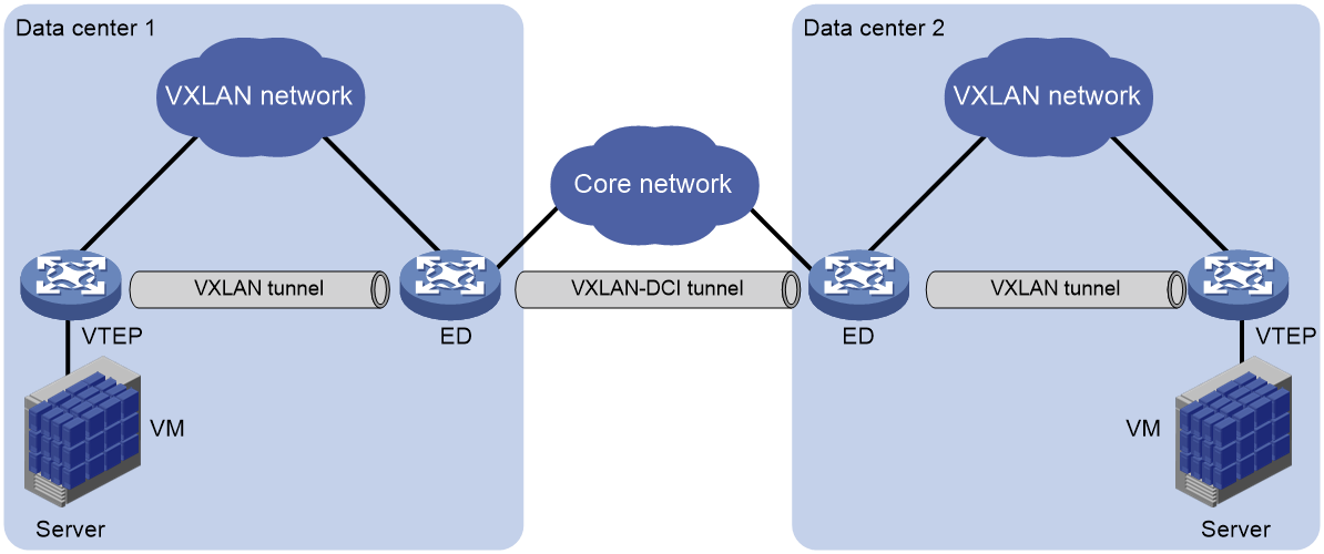
As shown in Figure 1, the EVPN-DCI network contains VTEPs and edge devices (EDs) located at the edge of the transport network. A VXLAN tunnel is established between a VTEP and an ED, and a VXLAN-DCI tunnel is established between two EDs. VXLAN-DCI tunnels use VXLAN encapsulation. Each ED de-encapsulates incoming VXLAN packets and re-encapsulates them based on the destination before forwarding the packets through a VXLAN or VXLAN-DCI tunnel.
Figure 1 EVPN-DCI network model
Working mechanisms
In an EVPN-DCI network, BGP EVPN peer relationships are established between EDs and between EDs and VTEPs. When advertising routes to a VTEP or another ED, an ED replaces the routes' nexthop IP address and router MAC address with its IP address and router MAC address.
In an EVPN-DCI network, a VTEP and an ED use a VXLAN tunnel to send traffic, and two EDs use a VXLAN-DCI tunnel to send traffic. An ED de-encapsulates incoming VXLAN packets and re-encapsulates them before forwarding the packets through a VXLAN or VXLAN-DCI tunnel.
Restrictions and guidelines: EVPN-DCI configuration
On an ED, make sure the VSI interfaces configured with L3 VXLAN IDs use the same MAC address. To modify the MAC address of a VSI interface, use the mac-address command.
Before you can configure EVPN-DCI, you must perform the following tasks:
· Set the system operating mode to VXLAN by using the switch-mode 1 command. For more information about setting the system operating mode, see device management in Fundamentals Configuration Guide.
· Save the configuration.
· Reboot the device.
EVPN-DCI tasks at a glance
To configure EVPN-DCI, perform the following tasks on EDs:
1. Enabling DCI
2. Configuring an ED to modify BGP EVPN routes
a. Enabling route nexthop replacement and route router MAC replacement
b. (Optional.) Enabling an ED to replace the L3 VXLAN ID, RD, and route targets of BGP EVPN routes
Use this feature to enable communication between data centers that use different L3 VXLAN IDs or route targets or hide the L3 VXLAN ID of a data center.
3. (Optional.) Suppressing BGP EVPN route advertisement
To reduce the number of BGP EVPN routes on EDs of an EVPN-DCI network, suppress the advertisement of specific BGP EVPN routes on the EDs.
Prerequisites for EVPN-DCI
Before you configure EVPN-DCI, complete basic EVPN configuration for each data center. For more information about basic EVPN configuration, see "Configuring EVPN VXLAN."
Enabling DCI
About this task
For EDs to automatically establish VXLAN-DCI tunnels, you must enable DCI on the Layer 3 interfaces that interconnect the EDs.
An ED establishes VXLAN-DCI tunnels based on BGP EVPN routes. If DCI is disabled on the outgoing interfaces to remote sites, EDs cannot establish VXLAN-DCI tunnels.
Procedure
1. Enter system view.
system-view
2. Enter interface view.
interface interface-type interface-number
Subinterfaces of a DCI-enabled interface inherit configuration of the interface.
3. Enable DCI.
dci enable
By default, DCI is disabled on an interface.
Configuring an ED to modify BGP EVPN routes
Enabling route nexthop replacement and route router MAC replacement
1. Enter system view.
system-view
2. Configure a global router ID.
router id router-id
By default, no global router ID is configured.
3. Enable a BGP instance and enter BGP instance view.
bgp as-number [ instance instance-name ]
By default, BGP is disabled, and no BGP instances exist.
4. Specify local VTEPs and remote EDs as BGP peers.
peer { group-name | ipv4-address [ mask-length ] | ipv6-address [ prefix-length ] } as-number as-number
5. Create the BGP EVPN address family and enter BGP EVPN address family view.
address-family l2vpn evpn
6. Enable BGP to exchange BGP EVPN routes with a peer or peer group.
peer { group-name | ipv4-address [ mask-length ] | ipv6-address [ prefix-length ] } enable
By default, BGP does not exchange BGP EVPN routes with peers.
7. Set the local router as the next hop for routes advertised to a peer or peer group.
peer { group-name | ipv4-address [ mask-length ] | ipv6-address [ prefix-length ] } next-hop-local
The default settings for this command are as follows:
¡ BGP sets the local router as the next hop for all routes advertised to an EBGP peer or peer group.
¡ BGP does not modify the next hop for EBGP routes advertised to an IBGP peer or peer group.
The peers specified in this task must be VTEPs in the local data center.
8. Enable route router MAC replacement for a peer or peer group.
peer { group-name | ipv4-address [ mask-length ] | ipv6-address [ prefix-length ] } router-mac-local [ dci ]
By default, the device does not modify the router MAC address of routes before advertising the routes.
This command enables the device to use its router MAC address to replace the router MAC address of routes received from and advertised to a peer or peer group.
The peers specified in this task must be remote EDs.
If you do not specify the dci keyword, whether the device establishes VXLAN-DCI tunnels with the peer or peer group depends on the dci enable command configuration in interface view.
Enabling an ED to replace the L3 VXLAN ID, RD, and route targets of BGP EVPN routes
About this task
In an EVPN-DCI network, use this feature to hide the L3 VXLAN IDs of data centers or enable communication between data centers that use different L3 VXLAN IDs or route targets.
After you enable this feature on an ED, the ED performs the following operations after receiving BGP EVPN routes:
1. Matches the route targets of the routes with the import route targets of local VPN instances.
2. Replaces the L3 VXLAN ID, RD, and route targets of the routes with those of the matching local VPN instance.
3. Advertises the routes to a VTEP or remote ED.
After you execute the peer re-originated command, the ED advertises only reoriginated BGP EVPN routes. For the ED to advertise both original and reoriginated BGP EVPN routes, execute the peer advertise original-route command.
An ED configured with the peer re-originated and peer advertise original-route commands advertises both original and reoriginated BGP EVPN routes. For the ED to advertise only original BGP EVPN routes, execute the peer suppress re-originated command on the ED.
Restrictions and guidelines
If the RD of a received BGP EVPN route is identical to the RD of the matching local VPN instance, an ED does not replace the L3 VXLAN ID and route targets of the route or reoriginate the route. As a result, the ED does not advertise the route. As a best practice, assign unique RDs to VPN instances on different EVPN gateways and EDs when you use this feature.
Procedure
1. Enter system view.
system-view
2. Enter BGP instance view.
bgp as-number [ instance instance-name ]
3. Enter BGP EVPN address family view.
address-family l2vpn evpn
4. Replace the L3 VXLAN ID, RD, and route targets (optional) of received BGP EVPN routes.
peer { group-name | ipv4-address [ mask-length ] | ipv6-address [ prefix-length ] } re-originated [ imet | ip-prefix | mac-ip ] [ replace-rt ]
By default, the device does not modify the BGP EVPN routes that are received from peers or peer groups.
5. (Optional.) Enable the device to advertise original BGP EVPN routes together with the reoriginated BGP EVPN routes after the peer re-originated command is executed.
peer { group-name | ipv4-address [ mask-length ] | ipv6-address [ prefix-length ] } advertise original-route
By default, the device advertises only reoriginated BGP EVPN routes to peers and peer groups after the peer re-originated command is executed.
6. (Optional.) Suppress advertisement of reoriginated BGP EVPN routes to a peer or peer group.
peer { group-name | ipv4-address [ mask-length ] | ipv6-address [ prefix-length ] } suppress re-originated { imet | ip-prefix | mac-ip }
By default, the device advertises reoriginated BGP EVPN routes to peers and peer groups after the peer re-originated command is executed.
Suppressing BGP EVPN route advertisement
About this task
To reduce the number of BGP EVPN routes on EDs of an EVPN-DCI network, suppress the advertisement of specific BGP EVPN routes on the EDs.
Restrictions and guidelines
If two VSI interfaces on EVPN gateways of different data centers use the same IP address, do not suppress the advertisement of MAC/IP advertisement routes on the EDs of the data centers. If you suppress the advertisement of these routes, the EDs cannot communicate with each other.
Procedure
1. Enter system view.
system-view
2. Enter BGP instance view.
bgp as-number [ instance instance-name ]
3. Enter BGP EVPN address family view.
address-family l2vpn evpn
4. Suppress the advertisement of specific BGP EVPN routes to a peer or peer group.
peer { group-name | ipv4-address [ mask-length ] | ipv6-address [ prefix-length ] } advertise evpn-route suppress { ip-prefix | mac-ip }
By default, advertisement of BGP EVPN routes is not suppressed.
EVPN-DCI configuration examples
Example: Configuring EVPN-DCI Layer 3 communication (IPv4 underlay network)
Network configuration
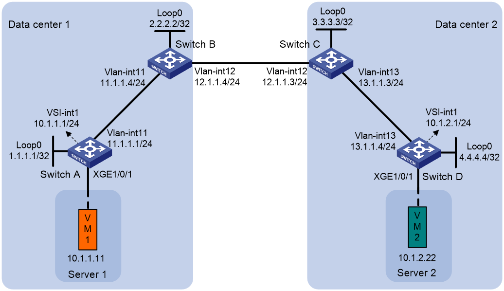
As shown in Figure 2:
· Configure VXLAN 10 for data center 1, and configure VXLAN 20 for data center 2.
· Configure Switch A and Switch D as distributed EVPN gateways to perform Layer 3 forwarding between VXLAN 10 and VXLAN 20.
· Configure Switch B and Switch C as EDs.
|
|
NOTE: This example provides configuration of IPv4 sites. The configuration procedure does not differ between IPv4 and IPv6 sites. |
Procedure
1. Set the VXLAN hardware resource mode on Switches A through D and reboot the switches for the mode to take effect. This step uses Switch A as an example.
<SwitchA> system-view
[SwitchA] switch-mode 1
Reboot device to make the configuration take effect.
[SwitchA] quit
<SwitchA> reboot
Start to check configuration with next startup configuration file, please wait..
.......DONE!
Current configuration may be lost after the reboot, save current configuration?
[Y/N]:y
This command will reboot the device. Continue? [Y/N]:y
2. Configure IP addresses and unicast routing settings:
# On VM 1, specify 10.1.1.1 as the gateway address. On VM 2, specify 10.1.2.1 as the gateway address. (Details not shown.)
# Assign IP addresses to interfaces, as shown in Figure 2. (Details not shown.)
# Configure OSPF on the transport network for the switches to reach one another. (Details not shown.)
3. Configure Switch A:
# Enable L2VPN.
<SwitchA> system-view
[SwitchA] l2vpn enable
# Disable remote MAC address learning and remote ARP learning.
[SwitchA] vxlan tunnel mac-learning disable
[SwitchA] vxlan tunnel arp-learning disable
# Create VXLAN 10 on VSI vpna.
[SwitchA] vsi vpna
[SwitchA-vsi-vpna] vxlan 10
[SwitchA-vsi-vpna-vxlan-10] quit
# Create an EVPN instance on VSI vpna. Configure the switch to automatically generate an RD and a route target for the EVPN instance.
[SwitchA-vsi-vpna] evpn encapsulation vxlan
[SwitchA-vsi-vpna-evpn-vxlan] route-distinguisher auto
[SwitchA-vsi-vpna-evpn-vxlan] vpn-target auto
[SwitchA-vsi-vpna-evpn-vxlan] quit
[SwitchA-vsi-vpna] quit
# Configure BGP to advertise BGP EVPN routes.
[SwitchA] bgp 100
[SwitchA-bgp-default] peer 2.2.2.2 as-number 100
[SwitchA-bgp-default] peer 2.2.2.2 connect-interface loopback 0
[SwitchA-bgp-default] address-family l2vpn evpn
[SwitchA-bgp-default-evpn] peer 2.2.2.2 enable
[SwitchA-bgp-default-evpn] quit
[SwitchA-bgp-default] quit
# On Ten-GigabitEthernet 1/0/1, create Ethernet service instance 1000 to match VLAN 100.
[SwitchA] interface ten-gigabitethernet 1/0/1
[SwitchA-Ten-GigabitEthernet1/0/1] port link-type trunk
[SwitchA-Ten-GigabitEthernet1/0/1] port trunk permit vlan 100
[SwitchA-Ten-GigabitEthernet1/0/1] service-instance 1000
[SwitchA-Ten-GigabitEthernet1/0/1-srv1000] encapsulation s-vid 100
# Map Ethernet service instance 1000 to VSI vpna.
[SwitchA-Ten-GigabitEthernet1/0/1-srv1000] xconnect vsi vpna
[SwitchA-Ten-GigabitEthernet1/0/1-srv1000] quit
# Configure RD and route target settings for VPN instance vpn1.
[SwitchA] ip vpn-instance vpn1
[SwitchA-vpn-instance-vpn1] route-distinguisher 1:1
[SwitchA-vpn-instance-vpn1] address-family ipv4
[SwitchA-vpn-ipv4-vpn1] vpn-target 2:2
[SwitchA-vpn-ipv4-vpn1] quit
[SwitchA-vpn-instance-vpn1] address-family evpn
[SwitchA-vpn-evpn-vpn1] vpn-target 1:1
[SwitchA-vpn-evpn-vpn1] quit
[SwitchA-vpn-instance-vpn1] quit
# Configure VSI-interface 1 as a distributed gateway.
[SwitchA] interface vsi-interface 1
[SwitchA-Vsi-interface1] ip binding vpn-instance vpn1
[SwitchA-Vsi-interface1] ip address 10.1.1.1 255.255.255.0
[SwitchA-Vsi-interface1] mac-address 1-1-1
[SwitchA-Vsi-interface1] distributed-gateway local
[SwitchA-Vsi-interface1] quit
# Create VSI-interface 2. Associate VSI-interface 2 with VPN instance vpn1, and configure the L3 VXLAN ID as 1000 for the VPN instance.
[SwitchA] interface vsi-interface 2
[SwitchA-Vsi-interface2] ip binding vpn-instance vpn1
[SwitchA-Vsi-interface2] l3-vni 1000
[SwitchA-Vsi-interface2] quit
# Specify VSI-interface 1 as the gateway interface for VSI vpna.
[SwitchA] vsi vpna
[SwitchA-vsi-vpna] gateway vsi-interface 1
[SwitchA-vsi-vpna] quit
4. Configure Switch B:
# Enable L2VPN.
<SwitchB> system-view
[SwitchB] l2vpn enable
# Disable remote MAC address learning and remote ARP learning.
[SwitchB] vxlan tunnel mac-learning disable
[SwitchB] vxlan tunnel arp-learning disable
# Enable DCI on the Layer 3 interface that connects Switch B to Switch C for the switches to establish a VXLAN-DCI tunnel.
[SwitchB] interface vlan-interface 12
[SwitchB-Vlan-interface12] dci enable
[SwitchB-Vlan-interface12] quit
# Configure BGP to advertise BGP EVPN routes. Enable nexthop replacement for routes advertised to Switch A, and enable router MAC replacement for routes advertised to and received from Switch C.
[SwitchB] bgp 100
[SwitchB-bgp-default] peer 3.3.3.3 as-number 200
[SwitchB-bgp-default] peer 3.3.3.3 connect-interface loopback 0
[SwitchB-bgp-default] peer 3.3.3.3 ebgp-max-hop 64
[SwitchB-bgp-default] peer 1.1.1.1 as-number 100
[SwitchB-bgp-default] peer 1.1.1.1 connect-interface loopback 0
[SwitchB-bgp-default] address-family l2vpn evpn
[SwitchB-bgp-default-evpn] peer 3.3.3.3 enable
[SwitchB-bgp-default-evpn] peer 3.3.3.3 router-mac-local
[SwitchB-bgp-default-evpn] peer 1.1.1.1 enable
[SwitchB-bgp-default-evpn] peer 1.1.1.1 next-hop-local
[SwitchB-bgp-default-evpn] quit
[SwitchB-bgp-default] quit
# Configure RD and route target settings for VPN instance vpn1.
[SwitchB] ip vpn-instance vpn1
[SwitchB-vpn-instance-vpn1] route-distinguisher 1:2
[SwitchB-vpn-instance-vpn1] address-family ipv4
[SwitchB-vpn-ipv4-vpn1] vpn-target 2:2
[SwitchB-vpn-ipv4-vpn1] quit
[SwitchB-vpn-instance-vpn1] address-family evpn
[SwitchB-vpn-evpn-vpn1] vpn-target 1:1
[SwitchB-vpn-evpn-vpn1] quit
[SwitchB-vpn-instance-vpn1] quit
# Create VSI-interface 2. Associate VSI-interface 2 with VPN instance vpn1, and configure the L3 VXLAN ID as 1000 for the VPN instance.
[SwitchB] interface vsi-interface 2
[SwitchB-Vsi-interface2] ip binding vpn-instance vpn1
[SwitchB-Vsi-interface2] l3-vni 1000
[SwitchB-Vsi-interface2] quit
5. Configure Switch C:
# Enable L2VPN.
<SwitchC> system-view
[SwitchC] l2vpn enable
# Disable remote MAC address learning and remote ARP learning.
[SwitchC] vxlan tunnel mac-learning disable
[SwitchC] vxlan tunnel arp-learning disable
# Enable DCI on the Layer 3 interface that connects Switch C to Switch B for the switches to establish a VXLAN-DCI tunnel.
[SwitchC] interface vlan-interface 12
[SwitchC-Vlan-interface12] dci enable
[SwitchC-Vlan-interface12] quit
# Configure BGP to advertise BGP EVPN routes. Enable nexthop replacement for routes advertised to Switch D, and enable router MAC replacement for routes advertised to and received from Switch B.
[SwitchC] bgp 200
[SwitchC-bgp-default] peer 2.2.2.2 as-number 100
[SwitchC-bgp-default] peer 2.2.2.2 connect-interface Loopback 0
[SwitchC-bgp-default] peer 2.2.2.2 ebgp-max-hop 64
[SwitchC-bgp-default] peer 4.4.4.4 as-number 200
[SwitchC-bgp-default] peer 4.4.4.4 connect-interface Loopback 0
[SwitchC-bgp-default] address-family l2vpn evpn
[SwitchC-bgp-default-evpn] peer 2.2.2.2 enable
[SwitchC-bgp-default-evpn] peer 2.2.2.2 router-mac-local
[SwitchC-bgp-default-evpn] peer 4.4.4.4 enable
[SwitchC-bgp-default-evpn] peer 4.4.4.4 next-hop-local
[SwitchC-bgp-default-evpn] quit
[SwitchC-bgp-default] quit
# Configure RD and route target settings for VPN instance vpn1.
[SwitchC] ip vpn-instance vpn1
[SwitchC-vpn-instance-vpn1] route-distinguisher 1:3
[SwitchC-vpn-instance-vpn1] address-family ipv4
[SwitchC-vpn-ipv4-vpn1] vpn-target 2:2
[SwitchC-vpn-ipv4-vpn1] quit
[SwitchC-vpn-instance-vpn1] address-family evpn
[SwitchC-vpn-evpn-vpn1] vpn-target 1:1
[SwitchC-vpn-evpn-vpn1] quit
[SwitchC-vpn-instance-vpn1] quit
# Create VSI-interface 2. Associate VSI-interface 2 with VPN instance vpn1, and configure the L3 VXLAN ID as 1000 for the VPN instance.
[SwitchC] interface vsi-interface 2
[SwitchC-Vsi-interface2] ip binding vpn-instance vpn1
[SwitchC-Vsi-interface2] l3-vni 1000
[SwitchC-Vsi-interface2] quit
6. Configure Switch D:
# Enable L2VPN.
<SwitchD> system-view
[SwitchD] l2vpn enable
# Disable remote MAC address learning and remote ARP learning.
[SwitchD] vxlan tunnel mac-learning disable
[SwitchD] vxlan tunnel arp-learning disable
# Create an EVPN instance on VSI vpnb. Configure the switch to automatically generate an RD and a route target for the EVPN instance.
[SwitchD] vsi vpnb
[SwitchD-vsi-vpnb] evpn encapsulation vxlan
[SwitchD-vsi-vpnb-evpn-vxlan] route-distinguisher auto
[SwitchD-vsi-vpnb-evpn-vxlan] vpn-target auto
[SwitchD-vsi-vpnb-evpn-vxlan] quit
# Create VXLAN 20 on VSI vpnb.
[SwitchD-vsi-vpnb] vxlan 20
[SwitchD-vsi-vpnb-vxlan-20] quit
[SwitchD-vsi-vpnb] quit
# Configure BGP to advertise BGP EVPN routes.
[SwitchD] bgp 200
[SwitchD-bgp-default] peer 3.3.3.3 as-number 200
[SwitchD-bgp-default] peer 3.3.3.3 connect-interface Loopback 0
[SwitchD-bgp-default] address-family l2vpn evpn
[SwitchD-bgp-default-evpn] peer 3.3.3.3 enable
[SwitchD-bgp-default-evpn] quit
[SwitchD-bgp-default] quit
# On Ten-GigabitEthernet 1/0/1, create Ethernet service instance 3000 to match VLAN 3.
[SwitchD] interface ten-gigabitethernet 1/0/1
[SwitchD-Ten-GigabitEthernet1/0/1] port link-type trunk
[SwitchD-Ten-GigabitEthernet1/0/1] port trunk permit vlan 3
[SwitchD-Ten-GigabitEthernet1/0/1] service-instance 3000
[SwitchD-Ten-GigabitEthernet1/0/1-srv3000] encapsulation s-vid 3
# Map Ethernet service instance 3000 to VSI vpnb.
[SwitchD-Ten-GigabitEthernet1/0/1-srv3000] xconnect vsi vpnb
[SwitchD-Ten-GigabitEthernet1/0/1-srv3000] quit
# Configure RD and route target settings for VPN instance vpn1.
[SwitchD] ip vpn-instance vpn1
[SwitchD-vpn-instance-vpn1] route-distinguisher 1:4
[SwitchD-vpn-instance-vpn1] address-family ipv4
[SwitchD-vpn-ipv4-vpn1] vpn-target 2:2
[SwitchD-vpn-ipv4-vpn1] quit
[SwitchD-vpn-instance-vpn1] address-family evpn
[SwitchD-vpn-evpn-vpn1] vpn-target 1:1
[SwitchD-vpn-evpn-vpn1] quit
[SwitchD-vpn-instance-vpn1] quit
# Configure VSI-interface 1 as a distributed gateway.
[SwitchD] interface vsi-interface 1
[SwitchD-Vsi-interface1] ip binding vpn-instance vpn1
[SwitchD-Vsi-interface1] ip address 10.1.2.1 255.255.255.0
[SwitchD-Vsi-interface1] mac-address 1-2-1
[SwitchD-Vsi-interface1] distributed-gateway local
[SwitchD-Vsi-interface1] quit
# Create VSI-interface 2. Associate VSI-interface 2 with VPN instance vpn1, and configure the L3 VXLAN ID as 1000 for the VPN instance.
[SwitchD] interface vsi-interface 2
[SwitchD-Vsi-interface2] ip binding vpn-instance vpn1
[SwitchD-Vsi-interface2] l3-vni 1000
[SwitchD-Vsi-interface2] quit
# Specify VSI-interface 1 as the gateway interface for VSI vpnb.
[SwitchD] vsi vpnb
[SwitchD-vsi-vpnb] gateway vsi-interface 1
[SwitchD-vsi-vpnb] quit
Verifying the configuration
1. Verify the configuration on EDs. (This example uses Switch B.)
# Verify that the ED has discovered Switch A and Switch C through MAC/IP advertisement routes and IP prefix advertisement routes, and has established VXLAN and VXLAN-DCI tunnels to the switches.
[SwitchB] display evpn auto-discovery macip-prefix
Destination IP Source IP L3VNI Tunnel mode OutgoingInterface
1.1.1.1 2.2.2.2 1000 VXLAN Vsi-interface2
3.3.3.3 2.2.2.2 1000 VXLAN-DCI Vsi-interface2
# Verify that the VXLAN and VXLAN-DCI tunnels on the ED are up.
[SwitchB] display interface tunnel
Tunnel0
Current state: UP
Line protocol state: UP
Description: Tunnel0 Interface
Bandwidth: 64 kbps
Maximum transmission unit: 1464
Internet protocol processing: Disabled
Last clearing of counters: Never
Tunnel source 2.2.2.2, destination 1.1.1.1
Tunnel protocol/transport UDP_VXLAN/IP
Last 300 seconds input rate: 0 bytes/sec, 0 bits/sec, 0 packets/sec
Last 300 seconds output rate: 0 bytes/sec, 0 bits/sec, 0 packets/sec
Input: 0 packets, 0 bytes, 0 drops
Output: 0 packets, 0 bytes, 0 drops
Tunnel1
Current state: UP
Line protocol state: UP
Description: Tunnel1 Interface
Bandwidth: 64 kbps
Maximum transmission unit: 1464
Internet protocol processing: Disabled
Last clearing of counters: Never
Tunnel source 2.2.2.2, destination 3.3.3.3
Tunnel protocol/transport UDP_VXLAN-DCI/IP
Last 300 seconds input rate: 0 bytes/sec, 0 bits/sec, 0 packets/sec
Last 300 seconds output rate: 0 bytes/sec, 0 bits/sec, 0 packets/sec
Input: 0 packets, 0 bytes, 0 drops
Output: 0 packets, 0 bytes, 0 drops
# Verify that the ED has routes for the VMs.
[SwitchB] display ip routing-table vpn-instance vpn1
Destinations : 4 Routes : 4
Destination/Mask Proto Pre Cost NextHop Interface
10.1.1.0/24 BGP 255 0 1.1.1.1 Vsi2
10.1.1.11/32 BGP 255 0 1.1.1.1 Vsi2
10.1.2.0/24 BGP 255 0 3.3.3.3 Vsi2
10.1.2.22/32 BGP 255 0 3.3.3.3 Vsi2
2. Verify that VM 1 and VM 2 can communicate. (Details not shown.)
Example: Configuring EVPN-DCI Layer 3 communication (IPv6 underlay network)
Network configuration
As shown in Figure 3:
· Configure VXLAN 10 for data center 1, and configure VXLAN 20 for data center 2.
· Configure Switch A and Switch D as distributed EVPN gateways to perform Layer 3 forwarding between VXLAN 10 and VXLAN 20.
· Configure Switch B and Switch C as EDs.
|
|
NOTE: This example provides configuration of IPv6 sites. The configuration procedure does not differ between IPv4 and IPv6 sites. |

Procedure
1. Set the VXLAN hardware resource mode on Switches A through D and reboot the switches for the mode to take effect. This step uses Switch A as an example.
<SwitchA> system-view
[SwitchA] switch-mode 1
Reboot device to make the configuration take effect.
[SwitchA] quit
<SwitchA> reboot
Start to check configuration with next startup configuration file, please wait..
.......DONE!
Current configuration may be lost after the reboot, save current configuration?
[Y/N]:y
This command will reboot the device. Continue? [Y/N]:y
2. Configure IPv6 addresses and unicast routing settings:
# On VM 1, specify 10::1 as the gateway address. On VM 2, specify 20::1 as the gateway address. (Details not shown.)
# Assign IPv6 addresses to interfaces, as shown in Figure 3. (Details not shown.)
# Configure OSPFv3 on the transport network for the switches to reach one another. (Details not shown.)
3. Configure Switch A:
# Enable L2VPN.
<SwitchA> system-view
[SwitchA] l2vpn enable
# Disable remote MAC address learning and remote ND learning.
[SwitchA] vxlan tunnel mac-learning disable
[SwitchA] vxlan tunnel nd-learning disable
# Create VXLAN 10 on VSI vpna.
[SwitchA] vsi vpna
[SwitchA-vsi-vpna] vxlan 10
[SwitchA-vsi-vpna-vxlan-10] quit
# Create an EVPN instance on VSI vpna. Configure the switch to automatically generate an RD and a route target for the EVPN instance.
[SwitchA-vsi-vpna] evpn encapsulation vxlan
[SwitchA-vsi-vpna-evpn-vxlan] route-distinguisher auto
[SwitchA-vsi-vpna-evpn-vxlan] vpn-target auto
[SwitchA-vsi-vpna-evpn-vxlan] quit
[SwitchA-vsi-vpna] quit
# Configure BGP to advertise BGP EVPN routes.
[SwitchA] bgp 100
[SwitchA-bgp-default] router-id 1.1.1.1
[SwitchA-bgp-default] peer 2::2 as-number 100
[SwitchA-bgp-default] peer 2::2 connect-interface loopback 0
[SwitchA-bgp-default] address-family l2vpn evpn
[SwitchA-bgp-default-evpn] peer 2::2 enable
[SwitchA-bgp-default-evpn] quit
[SwitchA-bgp-default] quit
# On Ten-GigabitEthernet 1/0/1, create Ethernet service instance 1000 to match VLAN 100.
[SwitchA] interface ten-gigabitethernet 1/0/1
[SwitchA-Ten-GigabitEthernet1/0/1] port link-type trunk
[SwitchA-Ten-GigabitEthernet1/0/1] port trunk permit vlan 100
[SwitchA-Ten-GigabitEthernet1/0/1] service-instance 1000
[SwitchA-Ten-GigabitEthernet1/0/1-srv1000] encapsulation s-vid 100
# Map Ethernet service instance 1000 to VSI vpna.
[SwitchA-Ten-GigabitEthernet1/0/1-srv1000] xconnect vsi vpna
[SwitchA-Ten-GigabitEthernet1/0/1-srv1000] quit
# Configure RD and route target settings for VPN instance vpn1.
[SwitchA] ip vpn-instance vpn1
[SwitchA-vpn-instance-vpn1] route-distinguisher 1:1
[SwitchA-vpn-instance-vpn1] address-family ipv6
[SwitchA-vpn-ipv6-vpn1] vpn-target 2:2
[SwitchA-vpn-ipv6-vpn1] quit
[SwitchA-vpn-instance-vpn1] address-family evpn
[SwitchA-vpn-evpn-vpn1] vpn-target 1:1
[SwitchA-vpn-evpn-vpn1] quit
[SwitchA-vpn-instance-vpn1] quit
# Configure VSI-interface 1 as a distributed gateway.
[SwitchA] interface vsi-interface 1
[SwitchA-Vsi-interface1] ip binding vpn-instance vpn1
[SwitchA-Vsi-interface1] ipv6 address 10::1 64
[SwitchA-Vsi-interface1] mac-address 1-1-1
[SwitchA-Vsi-interface1] distributed-gateway local
[SwitchA-Vsi-interface1] quit
# Create VSI-interface 2. Associate VSI-interface 2 with VPN instance vpn1, and configure the L3 VXLAN ID as 1000 for the VPN instance.
[SwitchA] interface vsi-interface 2
[SwitchA-Vsi-interface2] ip binding vpn-instance vpn1
[SwitchA-Vsi-interface2] ipv6 address auto link-local
[SwitchA-Vsi-interface2] l3-vni 1000
[SwitchA-Vsi-interface2] quit
# Specify VSI-interface 1 as the gateway interface for VSI vpna.
[SwitchA] vsi vpna
[SwitchA-vsi-vpna] gateway vsi-interface 1
[SwitchA-vsi-vpna] quit
4. Configure Switch B:
# Enable L2VPN.
<SwitchB> system-view
[SwitchB] l2vpn enable
# Disable remote MAC address learning and remote ND learning.
[SwitchB] vxlan tunnel mac-learning disable
[SwitchB] vxlan tunnel nd-learning disable
# Enable DCI on the Layer 3 interface that connects Switch B to Switch C for the switches to establish a VXLAN-DCI tunnel.
[SwitchB] interface vlan-interface 12
[SwitchB-Vlan-interface12] dci enable
[SwitchB-Vlan-interface12] quit
# Configure BGP to advertise BGP EVPN routes. Enable nexthop replacement for routes advertised to Switch A, and enable router MAC replacement for routes advertised to and received from Switch C.
[SwitchB] bgp 100
[SwitchB-bgp-default] router-id 2.2.2.2
[SwitchB-bgp-default] peer 3::3 as-number 200
[SwitchB-bgp-default] peer 3::3 connect-interface loopback 0
[SwitchB-bgp-default] peer 3::3 ebgp-max-hop 64
[SwitchB-bgp-default] peer 1::1 as-number 100
[SwitchB-bgp-default] peer 1::1 connect-interface loopback 0
[SwitchB-bgp-default] address-family l2vpn evpn
[SwitchB-bgp-default-evpn] peer 3::3 enable
[SwitchB-bgp-default-evpn] peer 3::3 router-mac-local
[SwitchB-bgp-default-evpn] peer 1::1 enable
[SwitchB-bgp-default-evpn] peer 1::1 next-hop-local
[SwitchB-bgp-default-evpn] quit
[SwitchB-bgp-default] quit
# Configure RD and route target settings for VPN instance vpn1.
[SwitchB] ip vpn-instance vpn1
[SwitchB-vpn-instance-vpn1] route-distinguisher 1:2
[SwitchB-vpn-instance-vpn1] address-family ipv6
[SwitchB-vpn-ipv6-vpn1] vpn-target 2:2
[SwitchB-vpn-ipv6-vpn1] quit
[SwitchB-vpn-instance-vpn1] address-family evpn
[SwitchB-vpn-evpn-vpn1] vpn-target 1:1
[SwitchB-vpn-evpn-vpn1] quit
[SwitchB-vpn-instance-vpn1] quit
# Create VSI-interface 2. Associate VSI-interface 2 with VPN instance vpn1, and configure the L3 VXLAN ID as 1000 for the VPN instance.
[SwitchB] interface vsi-interface 2
[SwitchB-Vsi-interface2] ip binding vpn-instance vpn1
[SwitchB-Vsi-interface2] ipv6 address auto link-local
[SwitchB-Vsi-interface2] l3-vni 1000
[SwitchB-Vsi-interface2] quit
5. Configure Switch C:
# Enable L2VPN.
<SwitchC> system-view
[SwitchC] l2vpn enable
# Disable remote MAC address learning and remote ND learning.
[SwitchC] vxlan tunnel mac-learning disable
[SwitchC] vxlan tunnel nd-learning disable
# Enable DCI on the Layer 3 interface that connects Switch C to Switch B for the switches to establish a VXLAN-DCI tunnel.
[SwitchC] interface vlan-interface 12
[SwitchC-Vlan-interface12] dci enable
[SwitchC-Vlan-interface12] quit
# Configure BGP to advertise BGP EVPN routes. Enable nexthop replacement for routes advertised to Switch D, and enable router MAC replacement for routes advertised to and received from Switch B.
[SwitchC] bgp 200
[SwitchC-bgp-default] router-id 3.3.3.3
[SwitchC-bgp-default] peer 2::2 as-number 100
[SwitchC-bgp-default] peer 2::2 connect-interface Loopback 0
[SwitchC-bgp-default] peer 2::2 ebgp-max-hop 64
[SwitchC-bgp-default] peer 4::4 as-number 200
[SwitchC-bgp-default] peer 4::4 connect-interface Loopback 0
[SwitchC-bgp-default] address-family l2vpn evpn
[SwitchC-bgp-default-evpn] peer 2::2 enable
[SwitchC-bgp-default-evpn] peer 2::2 router-mac-local
[SwitchC-bgp-default-evpn] peer 4::4 enable
[SwitchC-bgp-default-evpn] peer 4::4 next-hop-local
[SwitchC-bgp-default-evpn] quit
[SwitchC-bgp-default] quit
# Configure RD and route target settings for VPN instance vpn1.
[SwitchC] ip vpn-instance vpn1
[SwitchC-vpn-instance-vpn1] route-distinguisher 1:3
[SwitchC-vpn-instance-vpn1] address-family ipv6
[SwitchC-vpn-ipv6-vpn1] vpn-target 2:2
[SwitchC-vpn-ipv6-vpn1] quit
[SwitchC-vpn-instance-vpn1] address-family evpn
[SwitchC-vpn-evpn-vpn1] vpn-target 1:1
[SwitchC-vpn-evpn-vpn1] quit
[SwitchC-vpn-instance-vpn1] quit
# Create VSI-interface 2. Associate VSI-interface 2 with VPN instance vpn1, and configure the L3 VXLAN ID as 1000 for the VPN instance.
[SwitchC] interface vsi-interface 2
[SwitchC-Vsi-interface2] ip binding vpn-instance vpn1
[SwitchC-Vsi-interface2] ipv6 address auto link-local
[SwitchC-Vsi-interface2] l3-vni 1000
[SwitchC-Vsi-interface2] quit
6. Configure Switch D:
# Enable L2VPN.
<SwitchD> system-view
[SwitchD] l2vpn enable
# Disable remote MAC address learning and remote ND learning.
[SwitchD] vxlan tunnel mac-learning disable
[SwitchD] vxlan tunnel nd-learning disable
# Create an EVPN instance on VSI vpnb. Configure the switch to automatically generate an RD and a route target for the EVPN instance.
[SwitchD] vsi vpnb
[SwitchD-vsi-vpnb] evpn encapsulation vxlan
[SwitchD-vsi-vpnb-evpn-vxlan] route-distinguisher auto
[SwitchD-vsi-vpnb-evpn-vxlan] vpn-target auto
[SwitchD-vsi-vpnb-evpn-vxlan] quit
# Create VXLAN 20 on VSI vpnb.
[SwitchD-vsi-vpnb] vxlan 20
[SwitchD-vsi-vpnb-vxlan-20] quit
[SwitchD-vsi-vpnb] quit
# Configure BGP to advertise BGP EVPN routes.
[SwitchD] bgp 200
[SwitchD-bgp-default] router-id 4.4.4.4
[SwitchD-bgp-default] peer 3::3 as-number 200
[SwitchD-bgp-default] peer 3::3 connect-interface Loopback 0
[SwitchD-bgp-default] address-family l2vpn evpn
[SwitchD-bgp-default-evpn] peer 3::3 enable
[SwitchD-bgp-default-evpn] quit
[SwitchD-bgp-default] quit
# On Ten-GigabitEthernet 1/0/1, create Ethernet service instance 3000 to match VLAN 3.
[SwitchD] interface ten-gigabitethernet 1/0/1
[SwitchD-Ten-GigabitEthernet1/0/1] port link-type trunk
[SwitchD-Ten-GigabitEthernet1/0/1] port trunk permit vlan 3
[SwitchD-Ten-GigabitEthernet1/0/1] service-instance 3000
[SwitchD-Ten-GigabitEthernet1/0/1-srv3000] encapsulation s-vid 3
# Map Ethernet service instance 3000 to VSI vpnb.
[SwitchD-Ten-GigabitEthernet1/0/1-srv3000] xconnect vsi vpnb
[SwitchD-Ten-GigabitEthernet1/0/1-srv3000] quit
# Configure RD and route target settings for VPN instance vpn1.
[SwitchD] ip vpn-instance vpn1
[SwitchD-vpn-instance-vpn1] route-distinguisher 1:4
[SwitchD-vpn-instance-vpn1] address-family ipv6
[SwitchD-vpn-ipv6-vpn1] vpn-target 2:2
[SwitchD-vpn-ipv6-vpn1] quit
[SwitchD-vpn-instance-vpn1] address-family evpn
[SwitchD-vpn-evpn-vpn1] vpn-target 1:1
[SwitchD-vpn-evpn-vpn1] quit
[SwitchD-vpn-instance-vpn1] quit
# Configure VSI-interface 1 as a distributed gateway.
[SwitchD] interface vsi-interface 1
[SwitchD-Vsi-interface1] ip binding vpn-instance vpn1
[SwitchD-Vsi-interface1] ipv6 address 20::1 64
[SwitchD-Vsi-interface1] mac-address 1-2-1
[SwitchD-Vsi-interface1] distributed-gateway local
[SwitchD-Vsi-interface1] quit
# Create VSI-interface 2. Associate VSI-interface 2 with VPN instance vpn1, and configure the L3 VXLAN ID as 1000 for the VPN instance.
[SwitchD] interface vsi-interface 2
[SwitchD-Vsi-interface2] ip binding vpn-instance vpn1
[SwitchD-Vsi-interface2] ipv6 address auto link-local
[SwitchD-Vsi-interface2] l3-vni 1000
[SwitchD-Vsi-interface2] quit
# Specify VSI-interface 1 as the gateway interface for VSI vpnb.
[SwitchD] vsi vpnb
[SwitchD-vsi-vpnb] gateway vsi-interface 1
[SwitchD-vsi-vpnb] quit
Verifying the configuration
1. Verify the configuration on EDs. (This example uses Switch B.)
# Verify that the ED has discovered Switch A and Switch C through MAC/IP advertisement routes and IP prefix advertisement routes, and has established VXLAN and VXLAN-DCI tunnels to the switches.
[SwitchB] display evpn ipv6 auto-discovery macip-prefix
Destination IP : 1::1
Source IP : 2::2
L3VNI : 1000
Tunnel mode : VXLAN
OutInterface : Vsi-interface2
Destination IP : 3::3
Source IP : 2::2
L3VNI : 1000
Tunnel mode : VXLAN-DCI
OutInterface : Vsi-interface2
# Verify that the VXLAN and VXLAN-DCI tunnels on the ED are up.
[SwitchB] display interface tunnel
Tunnel0
Current state: UP
Line protocol state: UP
Description: Tunnel1 Interface
Bandwidth: 64 kbps
Maximum transmission unit: 1464
Internet protocol processing: Disabled
Last clearing of counters: Never
Tunnel source 2::2, destination 1::1
Tunnel protocol/transport UDP_VXLAN/IPv6
Last 300 seconds input rate: 0 bytes/sec, 0 bits/sec, 0 packets/sec
Last 300 seconds output rate: 0 bytes/sec, 0 bits/sec, 0 packets/sec
Input: 0 packets, 0 bytes, 0 drops
Output: 0 packets, 0 bytes, 0 drops
Tunnel1
Current state: UP
Line protocol state: UP
Description: Tunnel2 Interface
Bandwidth: 64 kbps
Maximum transmission unit: 1464
Internet protocol processing: Disabled
Last clearing of counters: Never
Tunnel source 2::2, destination 3::3
Tunnel protocol/transport UDP_VXLAN-DCI/IPv6
Last 300 seconds input rate: 0 bytes/sec, 0 bits/sec, 0 packets/sec
Last 300 seconds output rate: 0 bytes/sec, 0 bits/sec, 0 packets/sec
Input: 0 packets, 0 bytes, 0 drops
Output: 0 packets, 0 bytes, 0 drops
# Verify that the ED has routes for the VMs.
[SwitchB] display ipv6 routing-table vpn-instance vpn1
Destinations : 7 Routes : 7
Destination: ::1/128 Protocol : Direct
NextHop : ::1 Preference: 0
Interface : InLoop0 Cost : 0
Destination: 10::/64 Protocol : BGP4+
NextHop : 1::1 Preference: 255
Interface : Vsi2 Cost : 0
Destination: 10::11/128 Protocol : BGP4+
NextHop : 1::1 Preference: 255
Interface : Vsi2 Cost : 0
Destination: 20::/64 Protocol : BGP4+
NextHop : 3::3 Preference: 255
Interface : Vsi2 Cost : 0
Destination: 20::22/128 Protocol : BGP4+
NextHop : 3::3 Preference: 255
Interface : Vsi2 Cost : 0
Destination: FE80::/10 Protocol : Direct
NextHop : :: Preference: 0
Interface : InLoop0 Cost : 0
Destination: FF00::/8 Protocol : Direct
NextHop : :: Preference: 0
Interface : NULL0
2. Verify that VM 1 and VM 2 can communicate. (Details not shown.)
