- Table of Contents
- Related Documents
-
| Title | Size | Download |
|---|---|---|
| 03-EVPN VPWS configuration | 166.31 KB |
Contents
Remote connection establishment
Configuring a remote connection
Configuring an Ethernet service instance on an interface
Configuring EVPN route advertisement
Restrictions and guidelines for EVPN route advertisement configuration
Enabling BGP to advertise BGP EVPN routes
Mapping an AC to a cross-connect
About mapping an AC to a cross-connect
Restrictions and guidelines for mapping an AC to a cross-connect
Mapping an Ethernet service instance to a cross-connect
Enabling packet statistics for an AC
Restrictions and guidelines for AC packet statistics
Enabling packet statistics for an Ethernet service instance
Enabling packet statistics for an EVPN PW
Display and maintenance commands for EVPN VPWS
EVPN VPWS configuration examples
Example: Configuring a remote connection between singlehomed sites
Configuring EVPN VPWS
About EVPN VPWS
EVPN Virtual Private Wire Service (VPWS) is a Layer 2 VPN technology that uses MP-BGP for BGP EVPN route advertisement in the control plane and MPLS for forwarding in the data plane. EVPN VPWS provides point-to-point forwarding services for users by using ACs and PWs associated with cross-connects without MAC address table lookup.
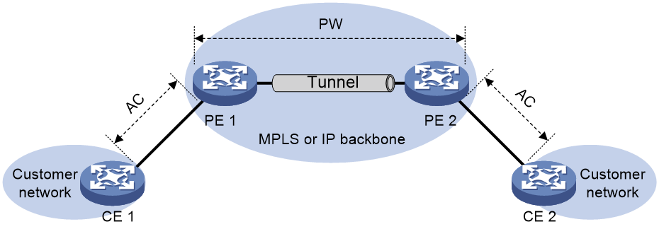
EVPN VPWS network model
As shown in Figure 1, an EVPN VPWS network contains the following devices:
· Customer edge (CE)—Customer device directly connected to the service provider network.
· Provider edge (PE)—Service provider device connected to CEs. PEs provide access to the EVPN VPWS network and forward traffic between customer network sites by using public tunnels.
A PE uses ACs, PWs, tunnels, and cross-connects to provide EVPN VPWS services.
· Attachment circuit (AC)—A physical or virtual link between a CE and a PE.
· Pseudowire (PW)—A virtual bidirectional connection between two PEs. A PW comprises a pair of virtual links in opposite directions.
· Public tunnel—A connection that carries one or more PWs across the MPLS or IP backbone. A public tunnel can be an LSP, GRE tunnel, or MPLS TE tunnel.
· Cross-connect—A connection formed by two physical or virtual circuits such as ACs and PWs. It switches packets between the two physical or virtual circuits. Cross-connects include AC to AC cross-connect and AC to PW cross-connect.
Remote connection establishment
To set up a remote EVPN VPWS connection:
1. Set up a public tunnel to carry one or more PWs between PEs.
2. Set up a PW to connect customer networks.
3. Set up an AC between a PE and a CE.
4. Bind the AC to the PW.
After the PE receives packets from the AC, it adds the PW label into the packets and sends the packets to the peer PE through the public tunnel.
After the peer PE receives the packets from the public tunnel, it removes the PW label of the packets and forwards the packets to the AC bound to the PW.
Public tunnel establishment
The public tunnel can be an LSP, MPLS TE, or GRE tunnel.
If multiple public tunnels are set up between two PEs, you can configure a tunnel policy to control tunnel selection. For more information about tunnel policies, see MPLS Configuration Guide.
If a PW is established over an LSP or MPLS TE tunnel, packets on the PW have two labels. The outer label is the public LSP or MPLS TE tunnel label that MPLS uses to forward the packet to the peer PE. The inner label is the PW label that the peer PE uses to forward the packet to the destination CE.
PW establishment
A PW is established between two PEs based on the local and remote service IDs configured on the PEs. In an EVPN VPWS network, each PE advertises its local service ID through Ethernet auto-discovery routes and compares received local service IDs with its remote service ID. A PE establishes a unidirectional virtual link to a peer If the local service ID advertised by the peer matches the remote service ID. PW establishment is finished when two virtual links in opposite directions are established between two PEs.
AC establishment
For EVPN VPWS, an AC is associated with a cross-connect and can be an Ethernet service instance on a PE. An Ethernet service instance is created on a Layer 2 Ethernet interface to match incoming customer traffic on that interface based on a frame match criterion.
AC-to-PW bindings
For PEs to forward packets between an AC and a PW, bind the AC to the PW.
EVPN VPWS tasks at a glance
Configuring a remote connection
To configure a remote connection, perform the following tasks:
2. Configure an AC
¡ Configuring an Ethernet service instance on an interface
3. Configuring EVPN route advertisement
a. Enabling BGP to advertise BGP EVPN routes
b. (Optional.) Maintaining BGP sessions
4. Configuring a cross-connect
6. Mapping an AC to a cross-connect
7. (Optional.) Enabling packet statistics for EVPN VPWS
¡ Enabling packet statistics for an AC
¡ Enabling packet statistics for an EVPN PW
Prerequisites for EVPN VPWS
To configure EVPN VPWS, you must perform the following tasks:
1. Configure an IGP to achieve IP connectivity within the backbone.
2. Configure basic MPLS, LDP, GRE, or MPLS TE to set up public tunnels across the backbone.
Enabling L2VPN
Prerequisites
Before you enable L2VPN, perform the following tasks:
· Configure an LSR ID for the PE by using the mpls lsr-id command.
· Enable MPLS by using the mpls enable command on the transport-facing interface of the PE.
For more information about the mpls lsr-id and mpls enable commands, see MPLS Command Reference.
Procedure
1. Enter system view.
system-view
2. Enable L2VPN.
l2vpn enable
By default, L2VPN is disabled.
Configuring an Ethernet service instance on an interface
About this task
When the PE is connected to a CE through a Layer 2 Ethernet interface or Layer 2 aggregate interface, you can configure an Ethernet service instance on the interface to match packets for the AC.
Restrictions and guidelines
You cannot repeat the encapsulation command to modify the frame match criterion of an Ethernet service instance. To change the frame match criterion, first execute the undo encapsulation command to remove the original frame match criterion.
If the frame match criterion of an Ethernet service instance is removed, the binding between the Ethernet service instance and the cross-connect is removed automatically.
For more information about the MPLS L2VPN commands used in this task, see MPLS Command Reference.
Procedure
1. Enter system view.
system-view
2. Enter interface view.
¡ Enter Layer 2 Ethernet interface view.
interface interface-type interface-number
¡ Enter Layer 2 aggregate interface view.
interface bridge-aggregation interface-number
3. Create an Ethernet service instance and enter Ethernet service instance view.
service-instance instance-id
4. Configure a frame match criterion for the Ethernet service instance.
¡ Match packets with the specified outer VLAN ID.
encapsulation s-vid vlan-id
¡ Match packets that do not have a VLAN tag.
encapsulation untagged
By default, no frame match criterion is configured.
Configuring EVPN route advertisement
Restrictions and guidelines for EVPN route advertisement configuration
For more information about the BGP commands used in this task, see Layer 3—IP Routing Command Reference.
Enabling BGP to advertise BGP EVPN routes
1. Enter system view.
system-view
2. Configure a global router ID.
router id router-id
By default, no global router ID is configured.
3. Enable a BGP instance and enter BGP instance view.
bgp as-number [ instance instance-name ]
By default, BGP is disabled and no BGP instances exist.
4. Specify remote PEs as BGP peers.
peer { group-name | ipv4-address [ mask-length ] } as-number as-number
5. Create the BGP EVPN address family and enter BGP EVPN address family view.
address-family l2vpn evpn
6. Enable BGP to exchange BGP EVPN routes with a peer or peer group.
peer { group-name | ipv4-address [ mask-length ] } enable
By default, BGP does not exchange BGP EVPN routes with peers.
Maintaining BGP sessions
Perform the following tasks in user view:
· Reset BGP sessions of the BGP EVPN address family.
reset bgp [ instance instance-name ] { as-number | ipv4-address [ mask-length ] | all | external | group group-name | internal } l2vpn evpn
· Soft-reset BGP sessions of the BGP EVPN address family.
refresh bgp [ instance instance-name ] { ipv4-address [ mask-length ] | all | external | group group-name | internal } { export | import } l2vpn evpn
Configuring a cross-connect
Restrictions and guidelines
For more information about the cross-connect commands used in this task, see MPLS L2VPN commands in MPLS Command Reference.
Procedure
1. Enter system view.
system-view
2. Create a cross-connect group and enter cross-connect group view.
xconnect-group group-name
3. (Optional.) Configure a description for the cross-connect group.
description text
By default, no description is configured for a cross-connect group.
4. (Optional.) Enable the cross-connect group.
undo shutdown
By default, the cross-connect group is enabled.
5. Create a cross-connect and enter cross-connect view.
connection connection-name
Configuring a PW
Configuring an EVPN PW
About this task
To establish an EVPN PW between two PEs, specify a local service ID and a remote service ID on both PEs. The local service ID specified on one PE must be the same as the remote service ID specified on the other PE.
Restrictions and guidelines
To modify an EVPN PW, first use the undo evpn local-service-id remote-service-id command to delete the original EVPN PW.
Procedure
1. Enter system view.
system-view
2. Enter cross-connect group view.
xconnect-group group-name
3. Create an EVPN instance for the cross-connect group and enter its view.
evpn encapsulation mpls
4. Configure an RD for the EVPN instance.
route-distinguisher route-distinguisher
By default, no RD is configured for the EVPN instance of a cross-connect group.
5. Configure route targets for the EVPN instance.
vpn-target { vpn-target&<1-8> } [ both | export-extcommunity | import-extcommunity ]
By default, no route targets are configured for the EVPN instance of a cross-connect group.
Make sure the following requirements are met:
¡ The import targets of the EVPN instance of a cross-connect group do not match the export targets of a VPN instance, the public instance, or the EVPN instance of a VSI.
¡ The export targets of the EVPN instance of a cross-connect group do not match the import targets of a VPN instance, the public instance, or the EVPN instance of a VSI.
6. Enter cross-connect view.
connection connection-name
7. (Optional.) Set an MTU for the PW.
mtu size
The default MTU is 1500 bytes.
8. Create an EVPN PW and enter its view.
evpn local-service-id local-service-id remote-service-id remote-service-id [ tunnel-policy tunnel-policy-name ] [ pw-class class-name ]
Do not use this command together with the peer command for a cross-connect.
Mapping an AC to a cross-connect
About mapping an AC to a cross-connect
After you map an Ethernet service instance to a cross-connect, packets received from the Ethernet service instance are forwarded to the PW or another AC bound to the cross-connect. An Ethernet service instance matches a list of VLANs on a site-facing interface. The PE assigns customer traffic from the VLANs to a cross-connect by mapping the Ethernet service instance to the cross-connect.
When you map an AC to a cross-connect, you can associate Track with the AC. Then, the AC is up only when one or more of the associated track entries are positive.
Restrictions and guidelines for mapping an AC to a cross-connect
This task is mutually exclusive with Ethernet link aggregation. If a Layer 2 Ethernet interface has been added to a link aggregation group, you cannot map an Ethernet service instance on the Layer 2 interface to a cross-connect, and vice versa.
Mapping an Ethernet service instance to a cross-connect
1. Enter system view.
system-view
2. Enter cross-connect group view.
xconnect-group group-name
3. Enter cross-connect view.
connection connection-name
4. Map an Ethernet service instance to the cross-connect.
ac interface interface-type interface-number service-instance instance-id [ access-mode { ethernet | vlan } ] [ track track-entry-number&<1-3> ]
By default, no Ethernet service instance is mapped to a cross-connect.
Enabling packet statistics for an AC
Restrictions and guidelines for AC packet statistics
For the statistics enable command to take effect on an Ethernet service instance, you must configure a frame match criterion for the Ethernet service instance and map it to a cross-connect. When you modify the frame match criterion or cross-connect mapping, the packet statistics of the instance are cleared. To display the statistics, use the display l2vpn service-instance verbose command.
To clear packet statistics for ACs, use the reset l2vpn statistics ac command.
Enabling packet statistics for an Ethernet service instance
1. Enter system view.
system-view
2. Enter interface view.
¡ Enter Layer 2 Ethernet interface view.
interface interface-type interface-number
¡ Enter Layer 2 aggregate interface view.
interface bridge-aggregation interface-number
3. Enter Ethernet service instance view.
service-instance instance-id
4. Enable packet statistics for the Ethernet service instance.
statistics enable
By default, the packet statistics feature is disabled for all Ethernet service instances.
Enabling packet statistics for an EVPN PW
Restrictions and guidelines
To display packet statistics for EVPN PWs, use the display l2vpn pw command.
To clear packet statistics for EVPN PWs, use the reset l2vpn statistics pw command.
Procedure
1. Enter system view.
system-view
2. Enter cross-connect group view.
xconnect-group group-name
3. Enter cross-connect view.
connection connection-name
4. Enter EVPN PW view.
evpn local-service-id local-service-id remote-service-id remote-service-id [ tunnel-policy tunnel-policy-name ] [ pw-class class-name ]
5. Enable packet statistics for the EVPN PW.
statistics enable
By default, packet statistics is disabled for an EVPN PW.
Display and maintenance commands for EVPN VPWS
Execute display commands in any view and reset commands in user view.
For more information about the following BGP commands, see Layer 3—IP Routing Command Reference:
· display bgp group.
· display bgp peer.
· display bgp update-group.
For more information about the following MPLS L2VPN commands, see MPLS Command Reference:
· display l2vpn forwarding.
· display l2vpn pw.
· display l2vpn service-instance.
· reset l2vpn statistics ac.
· reset l2vpn statistics pw.
For more information about the display l2vpn pw bfd command, see MPLS OAM commands in MPLS Command Reference.
|
Task |
Command |
|
Display BGP peer group information. |
display bgp [ instance instance-name ] group l2vpn evpn [ group-name group-name ] |
|
Display BGP peer or peer group information. |
display bgp [ instance instance-name ] peer l2vpn evpn [ ipv4-address mask-length | { ipv4-address | group-name group-name } log-info | [ ipv4-address ] verbose ] |
|
Display information about BGP update groups. |
display bgp [ instance instance-name ] update-group l2vpn evpn [ ipv4-address ] |
|
Display cross-connect forwarding information. |
display l2vpn forwarding { ac | pw } [ xconnect-group group-name ] [ slot slot-number ] [ verbose ] |
|
Display L2VPN PW information. |
display l2vpn pw [ xconnect-group group-name ] [ protocol { bgp | ldp | evpn | static } ] [ verbose ] |
|
Display BFD information for PWs. |
display l2vpn pw bfd [ peer peer-ip remote-service-id remote-service-id ] |
|
Display Ethernet service instance information. |
display l2vpn service-instance [ interface interface-type interface-number [ service-instance instance-id ] ] [ verbose ] |
|
Display EVPN information about cross-connects. |
display evpn xconnect-group [ name group-name [ connection connection-name ] ] [ count ] |
|
Clear packet statistics for ACs. |
reset l2vpn statistics ac [ interface interface-type interface-number service-instance instance-id ] |
|
Clear packet statistics for PWs. |
reset l2vpn statistics pw [ vsi vsi-name [ link link-id ] ] |
EVPN VPWS configuration examples
Example: Configuring a remote connection between singlehomed sites
Network configuration
As shown in Figure 2, set up a remote connection between CE 1 and CE 2 for users in VLAN 10 of site 1 and site 2 to communicate through EVPN VPWS over the MPLS or IP backbone network.
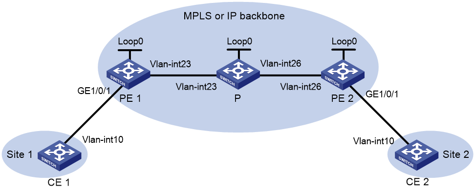
|
Device |
Interface |
IP address |
Device |
Interface |
IP address |
|
CE 1 |
Vlan-int10 |
10.1.1.10/24 |
P |
Loop0 |
3.3.3.3/32 |
|
PE 1 |
Loop0 |
1.1.1.1/32 |
|
Vlan-int23 |
11.1.1.2/24 |
|
|
Vlan-int23 |
11.1.1.1/24 |
|
Vlan-int26 |
11.1.2.2/24 |
|
CE 2 |
Vlan-int10 |
10.1.1.20/24 |
PE 2 |
Loop0 |
2.2.2.2/32 |
|
|
|
|
|
Vlan-int26 |
11.1.2.1/24 |
Procedure
1. Configure Switch A, Switch B, and Switch C to operate in MPLS mode, and then reboot the switches. This step uses Switch A as an example.
<SwitchA> system-view
[SwitchA] switch-mode 3
Reboot device to make the configuration take effect.
[SwitchA] quit
<SwitchA> reboot
Start to check configuration with next startup configuration file, please wait..
.......DONE!
Current configuration may be lost after the reboot, save current configuration?
[Y/N]:y
This command will reboot the device. Continue? [Y/N]:y
2. Create VLANs on all devices and assign interfaces to the VLANs. (Details not shown.)
3. Configure CE 1.
<CE1> system-view
[CE1] interface vlan-interface 10
[CE1-Vlan-interface10] ip address 10.1.1.10 24
[CE1-Vlan-interface10] quit
4. Configure PE 1:
# Configure the LSR ID.
<PE1> system-view
[PE1] interface loopback 0
[PE1-LoopBack0] ip address 1.1.1.1 32
[PE1-LoopBack0] quit
[PE1] mpls lsr-id 1.1.1.1
# Enable L2VPN.
[PE1] l2vpn enable
# Enable global LDP.
[PE1] mpls ldp
[PE1-ldp] quit
# Configure VLAN-interface 23 (the interface connected to the P device), and enable LDP on the interface.
[PE1] interface vlan-interface 23
[PE1-Vlan-interface23] ip address 11.1.1.1 24
[PE1-Vlan-interface23] mpls enable
[PE1-Vlan-interface23] mpls ldp enable
[PE1-Vlan-interface23] undo shutdown
[PE1-Vlan-interface23] quit
# Configure OSPF for LDP to create LSPs.
[PE1] ospf
[PE1-ospf-1] area 0
[PE1-ospf-1-area-0.0.0.0] network 11.1.1.0 0.0.0.255
[PE1-ospf-1-area-0.0.0.0] network 1.1.1.1 0.0.0.0
[PE1-ospf-1-area-0.0.0.0] quit
[PE1-ospf-1] quit
# Create an IBGP connection to PE 2, and enable BGP to advertise L2VPN information to PE 2.
[PE1] bgp 100
[PE1-bgp-default] peer 2.2.2.2 as-number 100
[PE1-bgp-default] peer 2.2.2.2 connect-interface loopback 0
[PE1-bgp-default] address-family l2vpn evpn
[PE1-bgp-default-evpn] peer 2.2.2.2 enable
[PE1-bgp-default-evpn] quit
[PE1-bgp-default] quit
# Configure Ethernet service instance 1000 to match VLAN 10 on Ten-GigabitEthernet 1/0/1 (the interface connected to CE 1).
[PE1] interface ten-gigabitethernet 1/0/1
[PE1-Ten-GigabitEthernet1/0/1] service-instance 1000
[PE1-Ten-GigabitEthernet1/0/1-srv1000] encapsulation s-vid 10
[PE1-Ten-GigabitEthernet1/0/1-srv1000] quit
[PE1-Ten-GigabitEthernet1/0/1] quit
# Create a cross-connect group named vpna, create an EVPN instance for it, and enable MPLS encapsulation. Configure an RD and route targets for the EVPN instance.
[PE1] xconnect-group vpna
[PE1-xcg-vpna] evpn encapsulation mpls
[PE1-xcg-vpna-evpn-mpls] route-distinguisher 1:1
[PE1-xcg-vpna-evpn-mpls] vpn-target 1:1 export-extcommunity
[PE1-xcg-vpna-evpn-mpls] vpn-target 1:1 import-extcommunity
[PE1-xcg-vpna-evpn-mpls] quit
# Create cross-connect pw1 and map Ethernet service instance 1000 on Ten-GigabitEthernet 1/0/1 to it. Create an EVPN PW on the cross-connect.
[PE1-xcg-vpna] connection pw1
[PE1-xcg-vpna-pw1] ac interface ten-gigabitethernet 1/0/1 service-instance 1000
[PE1-xcg-vpna-pw1-Ten-GigabitEthernet1/0/1-srv1000] quit
[PE1-xcg-vpna-pw1] evpn local-service-id 1 remote-service-id 2
[PE1-xcg-vpna-pw1-1-2] quit
[PE1-xcg-vpna-pw1] quit
[PE1-xcg-vpna] quit
5. Configure the P device:
# Configure the LSR ID.
<P> system-view
[P] interface loopback 0
[P-LoopBack0] ip address 3.3.3.3 32
[P-LoopBack0] quit
[P] mpls lsr-id 3.3.3.3
# Enable global LDP.
[P] mpls ldp
[P-ldp] quit
# Configure VLAN-interface 23 (the interface connected to PE 1), and enable LDP on the interface.
[P] interface vlan-interface 23
[P-Vlan-interface23] ip address 11.1.1.2 24
[P-Vlan-interface23] mpls enable
[P-Vlan-interface23] mpls ldp enable
[P-Vlan-interface23] undo shutdown
[P-Vlan-interface23] quit
# Configure VLAN-interface 26 (the interface connected to PE 2), and enable LDP on the interface.
[P] interface vlan-interface 26
[P-Vlan-interface26] ip address 11.1.2.2 24
[P-Vlan-interface26] mpls enable
[P-Vlan-interface26] mpls ldp enable
[P-Vlan-interface26] undo shutdown
[P-Vlan-interface26] quit
# Configure OSPF for LDP to create LSPs.
[P] ospf
[P-ospf-1] area 0
[P-ospf-1-area-0.0.0.0] network 11.1.1.0 0.0.0.255
[P-ospf-1-area-0.0.0.0] network 11.1.2.0 0.0.0.255
[P-ospf-1-area-0.0.0.0] network 3.3.3.3 0.0.0.0
[P-ospf-1-area-0.0.0.0] quit
[P-ospf-1] quit
6. Configure PE 2:
# Configure the LSR ID.
<PE2> system-view
[PE2] interface loopback 0
[PE2-LoopBack0] ip address 2.2.2.2 32
[PE2-LoopBack0] quit
[PE2] mpls lsr-id 2.2.2.2
# Enable L2VPN.
[PE2] l2vpn enable
# Enable global LDP.
[PE2] mpls ldp
[PE2-ldp] quit
# Configure VLAN-interface 26 (the interface connected to the P device), and enable LDP on the interface.
[PE2] interface vlan-interface 26
[PE2-Vlan-interface26] ip address 11.1.2.1 24
[PE2-Vlan-interface26] mpls enable
[PE2-Vlan-interface26] mpls ldp enable
[PE2-Vlan-interface26] undo shutdown
[PE2-Vlan-interface26] quit
# Configure OSPF for LDP to create LSPs.
[PE2] ospf
[PE2-ospf-1] area 0
[PE2-ospf-1-area-0.0.0.0] network 2.2.2.2 0.0.0.0
[PE2-ospf-1-area-0.0.0.0] network 11.1.2.0 0.0.0.255
[PE2-ospf-1-area-0.0.0.0] quit
[PE2-ospf-1] quit
# Create an IBGP connection to PE 1, and enable BGP to advertise L2VPN information to PE 1.
[PE2] bgp 100
[PE2-bgp-default] peer 1.1.1.1 as-number 100
[PE2-bgp-default] peer 1.1.1.1 connect-interface loopback 0
[PE2-bgp-default] address-family l2vpn evpn
[PE2-bgp-default-evpn] peer 1.1.1.1 enable
[PE2-bgp-default-evpn] quit
[PE2-bgp-default] quit
# Configure Ethernet service instance 1000 to match VLAN 10 on Ten-GigabitEthernet 1/0/1 (the interface connected to CE 2).
[PE2] interface ten-gigabitethernet 1/0/1
[PE2-Ten-GigabitEthernet1/0/1] service-instance 1000
[PE2-Ten-GigabitEthernet1/0/1-srv1000] encapsulation s-vid 10
[PE2-Ten-GigabitEthernet1/0/1-srv1000] quit
[PE2-Ten-GigabitEthernet1/0/1] quit
# Create a cross-connect group named vpna, create an EVPN instance for it, and enable MPLS encapsulation. Configure an RD and route targets for the EVPN instance.
[PE2] xconnect-group vpna
[PE2-xcg-vpna] evpn encapsulation mpls
[PE2-xcg-vpna-evpn-mpls] route-distinguisher 1:1
[PE2-xcg-vpna-evpn-mpls] vpn-target 1:1 export-extcommunity
[PE2-xcg-vpna-evpn-mpls] vpn-target 1:1 import-extcommunity
[PE2-xcg-vpna-evpn-mpls] quit
# Create cross-connect pw1 and map Ethernet service instance 1000 on Ten-GigabitEthernet 1/0/1 to it. Create an EVPN PW on the cross-connect.
[PE2-xcg-vpna] connection pw1
[PE2-xcg-vpna-pw1] ac interface ten-gigabitethernet 1/0/1 service-instance 1000
[PE2-xcg-vpna-pw1-Ten-GigabitEthernet1/0/1-srv1000] quit
[PE2-xcg-vpna-pw1] evpn local-service-id 2 remote-service-id 1
[PE2-xcg-vpna-pw1-2-1] quit
[PE2-xcg-vpna-pw1] quit
[PE2-xcg-vpna] quit
7. Configure CE 2.
<CE2> system-view
[CE2] interface vlan-interface 10
[CE2-Vlan-interface10] ip address 10.1.1.20 24
[CE2-Vlan-interface10] quit
Verifying the configuration
# Verify that an EVPN PW has been established between PE 1 and PE 2.
[PE1] display l2vpn pw
Flags: M - main, B - backup, E - ecmp, BY - bypass, H - hub link, S - spoke link
N - no split horizon, A - administration, ABY - ac-bypass
PBY - pw-bypass
Total number of PWs: 1
1 up, 0 blocked, 0 down, 0 defect, 0 idle, 0 duplicate
Xconnect-group Name: vpna
Peer PWID/RmtSite/SrvID In/Out Label Proto Flag Link ID State
2.2.2.2 2 710127/710127 EVPN M 0 Up
# Verify that the EVPN information about the cross-connect on PE 1 is correct.
[PE1] display evpn xconnect-group
Flags: P - Primary, B - Backup, C - Control word
Xconnect group name: vpna
Connection Name: pw1
ESI : 0000.0000.0000.0000.0000
Local service ID : 1
Remote service ID : 2
Control word : Disable
In label : 710127
Local MTU : 1500
AC State : Up
PW type : VLAN
Nexthop ESI Out label Flags MTU State
2.2.2.2 0000.0000.0000.0000.0000 710127 P 1500 Up
# Verify that the EVPN information about the cross-connect on PE 2 is correct.
[PE2] display l2vpn pw
Flags: M - main, B - backup, E - ecmp, BY - bypass, H - hub link, S - spoke link
N - no split horizon, A - administration, ABY - ac-bypass
PBY - pw-bypass
Total number of PWs: 1
1 up, 0 blocked, 0 down, 0 defect, 0 idle, 0 duplicate
Xconnect-group Name: vpna
Peer PWID/RmtSite/SrvID In/Out Label Proto Flag Link ID State
1.1.1.1 1 710127/710127 EVPN M 0 Up
# Verify that CE 1 and CE 2 can ping each other. (Details not shown.)
