- Table of Contents
- Related Documents
-
| Title | Size | Download |
|---|---|---|
| 02-Basic MPLS configuration | 256.66 KB |
Restrictions and guidelines: basic MPLS configuration
Specifying the label type advertised by the egress node to the penultimate hop
Display and maintenance commands for MPLS
Configuring basic MPLS
About MPLS
Multiprotocol Label Switching (MPLS) provides connection-oriented label switching over connectionless IP backbone networks. It integrates both the flexibility of IP routing and the simplicity of Layer 2 switching.
MPLS features
MPLS has the following features:
· High speed and efficiency—MPLS uses short- and fixed-length labels to forward packets, avoiding complicated routing table lookups.
· Multiprotocol support—MPLS resides between the link layer and the network layer. It can work over various link layer protocols (for example, Ethernet) to provide connection-oriented services for various network layer protocols (for example, IPv4 and IPX).
· Good scalability—The connection-oriented switching and multilayer label stack features enable MPLS to deliver various extended services, such as VPN, traffic engineering, and QoS.
Basic concepts
FEC
MPLS groups packets with the same characteristics (such as packets with the same destination or service class) into a forwarding equivalence class (FEC). Packets of the same FEC are handled in the same way on an MPLS network.
Label
A label uniquely identifies an FEC and has local significance.
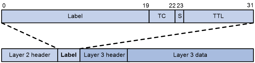
A label is encapsulated between the Layer 2 header and Layer 3 header of a packet. It is four bytes long and consists of the following fields:
· Label—20-bit label value.
· TC—3-bit traffic class, used for QoS. It is also called Exp.
· S—1-bit bottom of stack flag. A label stack can contain multiple labels. The label nearest to the Layer 2 header is called the top label, and the label nearest to the Layer 3 header is called the bottom label. The S field is set to 1 if the label is the bottom label and set to 0 if not.
· TTL—8-bit time to live field used for MPLS loop prevention.
LSR
A router that performs MPLS forwarding is a label switching router (LSR).
LSP
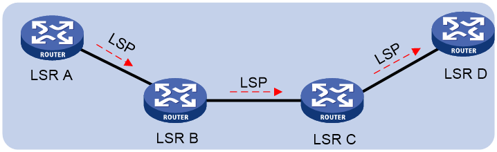
A label switched path (LSP) is the path along which packets of an FEC travel through an MPLS network.
An LSP is a unidirectional packet forwarding path. Two neighboring LSRs are called the upstream LSR and downstream LSR along the direction of an LSP. As shown in Figure 2, LSR B is the downstream LSR of LSR A, and LSR A is the upstream LSR of LSR B.
LFIB
The Label Forwarding Information Base (LFIB) on an MPLS network functions like the Forwarding Information Base (FIB) on an IP network. When an LSR receives a labeled packet, it searches the LFIB to obtain information for forwarding the packet. The information includes the label operation type, the outgoing label value, and the next hop.
Control plane and forwarding plane
An MPLS node consists of a control plane and a forwarding plane.
· Control plane—Assigns labels, distributes FEC-label mappings to neighbor LSRs, creates the LFIB, and establishes and removes LSPs.
· Forwarding plane—Forwards packets according to the LFIB.
MPLS network architecture
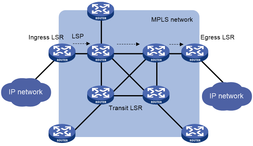
An MPLS network has the following types of LSRs:
· Ingress LSR—Ingress LSR of packets. It labels packets entering into the MPLS network.
· Transit LSR—Intermediate LSRs in the MPLS network. The transit LSRs on an LSP forward packets to the egress LSR according to labels.
· Egress LSR—Egress LSR of packets. It removes labels from packets and forwards the packets to their destination networks.
Figure 3 MPLS network architecture
LSP establishment
LSPs include static and dynamic LSPs.
Static LSP
To establish a static LSP, you must configure an LFIB entry on each LSR along the LSP. Establishing static LSPs consumes fewer resources than establishing dynamic LSPs, but static LSPs cannot automatically adapt to network topology changes. Therefore, static LSPs are suitable for small-scale networks with simple, stable topologies.
Dynamic LSP
A dynamic LSP is established by a label distribution protocol (also called an MPLS signaling protocol). A label distribution protocol classifies FECs, distributes FEC-label mappings, and establishes and maintains LSPs. Label distribution protocols include protocols designed specifically for label distribution, such as the Label Distribution Protocol (LDP), and protocols extended to support label distribution, such as MP-BGP.
In this document, the term "label distribution protocols" refers to all protocols for label distribution. The term "LDP" refers to the RFC 5036 LDP.
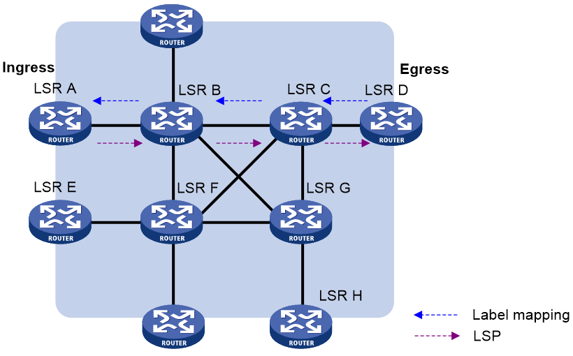
A dynamic LSP is established in the following steps:
1. A downstream LSR classifies FECs according to destination addresses.
2. The downstream LSR assigns a label for each FEC, and distributes the FEC-label binding to its upstream LSR.
3. The upstream LSR establishes an LFIB entry for the FEC according to the binding information.
After all LSRs along the LSP establish an LFIB entry for the FEC, a dynamic LSP is established for the packets of this FEC.
Figure 4 Dynamic LSP establishment
MPLS forwarding
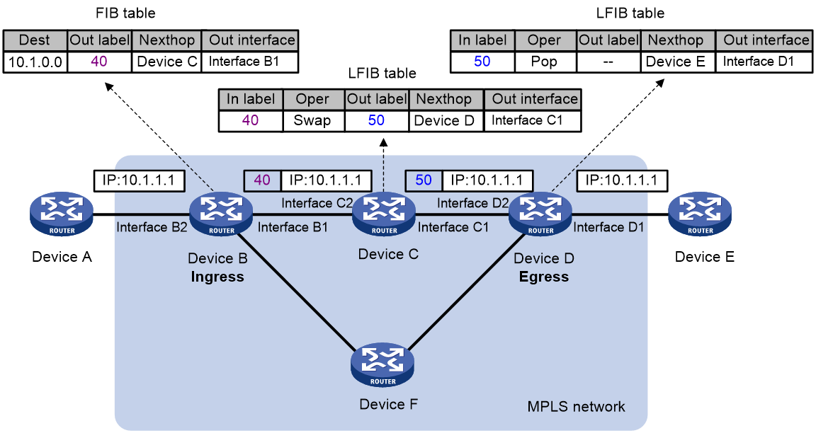
As shown in Figure 5, a packet is forwarded over the MPLS network as follows:
1. Device B (the ingress LSR) receives a packet with no label. Then, it performs the following operations:
a. Identifies the FIB entry that matches the destination address of the packet.
b. Adds the outgoing label (40, in this example) to the packet.
c. Forwards the labeled packet out of Interface B1 to the next hop LSR Device C.
2. When receiving the labeled packet, Device C processes the packet as follows:
a. Identifies the LFIB entry that has an incoming label of 40.
b. Uses the outgoing label 50 of the entry to replace label 40 in the packet.
c. Forwards the labeled packet out of Interface C1 to the next hop LSR Device D.
3. When receiving the labeled packet, Device D (the egress LSR) processes the packet as follows:
a. Identifies the LFIB entry that has an incoming label of 50.
b. Removes the label from the packet.
c. Forwards the packet out of Interface D1 to the next hop LSR Device E.
If the LFIB entry records no outgoing interface or next hop information, Device D performs the following operations:
a. Identifies the FIB entry by the IP header.
b. Forwards the packet according to the FIB entry.
PHP
An egress node must perform two forwarding table lookups to forward a packet:
· Two LFIB lookups (if the packet has more than one label).
· One LFIB lookup and one FIB lookup (if the packet has only one label).
The penultimate hop popping (PHP) feature can pop the label at the penultimate node, so the egress node only performs one table lookup.
A PHP-capable egress node can send either of the following null labels to the penultimate node:
· Implicit null label—The value of an implicit null label is 3. If an incoming packet matches an LFIB entry containing the implicit null label, the penultimate node pops the top label and forwards the packet to the egress node. The egress node forwards the packet based on the header of its next layer.
· Explicit null label—The value of an explicit null label is 0 for IPv4 networks and 2 for IPv6 networks. Sometimes, the egress node must use the TC field in the label to perform QoS. To keep the TC information, you can configure the egress node to send the penultimate node an explicit null label. If an incoming packet matches an LFIB entry containing the explicit null label, the penultimate hop replaces the top label value with value 0, and forwards the packet to the egress node. When the egress node receives the packet, it does not look up the LFIB table for the label of 0 or 2. The egress mode gets the TC information from the label, pops the label, and then forwards the packet based on the header of its next layer.
Protocols and standards
· RFC 3031, Multiprotocol Label Switching Architecture
· RFC 3032, MPLS Label Stack Encoding
· RFC 5462, Multiprotocol Label Switching (MPLS) Label Stack Entry: "EXP" Field Renamed to "Traffic Class" Field
Restrictions and guidelines: basic MPLS configuration
Before configuring MPLS, perform the following tasks:
· In standalone mode, execute the switch-mode 3 command to switch the operating mode of the device to MPLS, and then restart the device.
· In IRF mode, execute the switch-mode 4 command to switch the operating mode of the device to MPLS-IRF, and then restart the IRF fabric.
MPLS tasks at a glance
To configure basic MPLS, perform the following configuration tasks:
2. (Optional.) Setting MPLS MTU
3. (Optional.) Specifying the label type advertised by the egress node to the penultimate hop
4. (Optional.) Configuring TTL propagation
When TTL propagation is enabled, the ingress node copies the TTL value of an IP packet to the TTL field of the label. The IP tracert facility can show the real path along which the packet has traveled.
Enabling MPLS
Prerequisites
Before you enable MPLS, configure static routes or an IGP protocol to ensure IP connectivity among LSRs.
Procedure
1. Enter system view.
system-view
2. Configure an LSR ID for the local node.
mpls lsr-id lsr-id
By default, no LSR ID is configured.
An LSR ID must be unique in an MPLS network and in IP address format. As a best practice, use the IP address of a loopback interface as an LSR ID.
3. Enter the view of the interface that needs to perform MPLS forwarding.
interface interface-type interface-number
4. Enable MPLS on the interface.
mpls enable
By default, MPLS is disabled on the interface.
Setting MPLS MTU
About this task
MPLS adds the label stack between the link layer header and network layer header of each packet. To make sure the size of MPLS labeled packets is smaller than the MTU of an interface, configure an MPLS MTU on the interface.
MPLS compares each MPLS packet against the interface MPLS MTU. When the packet exceeds the MPLS MTU:
· If fragmentation is allowed, MPLS performs the following operations:
a. Removes the label stack from the packet.
b. Fragments the IP packet. The length of a fragment is the MPLS MTU minus the length of the label stack.
c. Adds the label stack to each fragment, and forwards the fragments.
· If fragmentation is not allowed, the LSR directly forwards the packet.
Restrictions and guidelines
If the MPLS MTU of an interface is greater than the MTU of the interface, data forwarding might fail on the interface.
Procedure
1. Enter system view.
system-view
2. Enter interface view.
interface interface-type interface-number
3. Set an MPLS MTU for the interface.
mpls mtu size
By default, no MPLS MTU is set on an interface. Fragmentation for MPLS packets is based on the IP MTU. If IP MTU is not configured, fragmentation for MPLS packets is based on the MTU of the interface. The length of a fragment does not include that of the MPLS label. Thus, after an MPLS label is added into a fragment, the length of the MPLS fragment might exceed the interface MTU.
Specifying the label type advertised by the egress node to the penultimate hop
About this task
Select the label type advertised by the egress node to the penultimate hop as follows:
· As a best practice, configure the egress node to advertise an implicit null label to the penultimate hop if the penultimate hop supports PHP.
· If you want to simplify packet forwarding on egress but keep labels to determine QoS policies, configure the egress node to advertise an explicit null label to the penultimate hop.
· Use non-null labels only in particular scenarios. For example, when OAM is configured on the egress node, the egress node can get the OAM function entity status only through non-null labels.
Restrictions and guidelines
For LDP LSPs, the mpls label advertise command triggers LDP to delete the LSPs established before the command is executed and then re-establish the LSPs.
For BGP LSPs, the mpls label advertise command takes effect only on the BGP LSPs established after the command is executed. To apply the new setting to BGP LSPs established before the command is executed, delete the routes corresponding to the BGP LSPs, and then redistribute the routes.
Procedure
1. Enter system view.
system-view
2. Specify the label type advertised by the egress node to the penultimate hop.
mpls label advertise { explicit-null | implicit-null | non-null }
By default, an egress node advertises an implicit null label to the penultimate hop.
Configuring TTL propagation
About this task
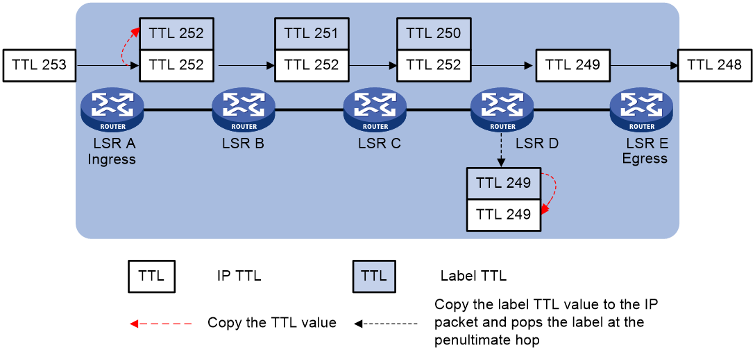
When TTL propagation is enabled, the ingress node copies the TTL value of an IP packet to the TTL field of the label. Each LSR on the LSP decreases the label TTL value by 1. The LSR that pops the label copies the remaining label TTL value back to the IP TTL of the packet. The IP TTL value can reflect how many hops the packet has traversed in the MPLS network. The IP tracert facility can show the real path along which the packet has traveled.
Figure 6 TTL propagation
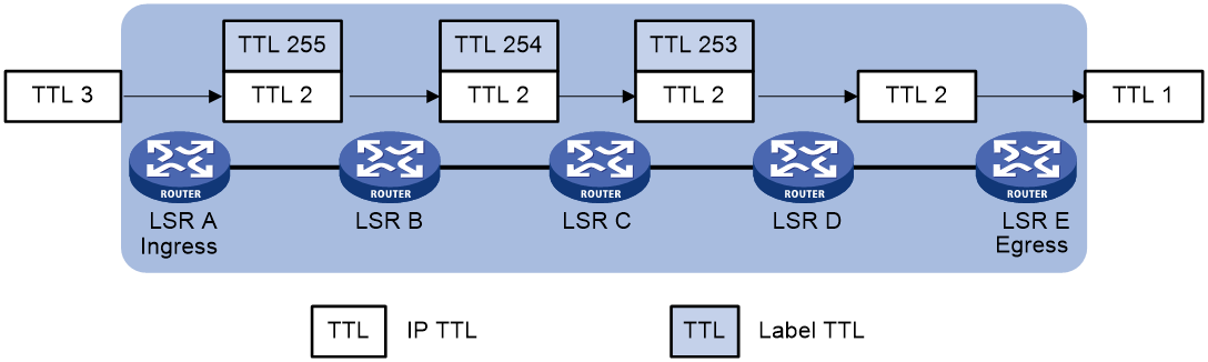
When TTL propagation is disabled, the ingress node sets the label TTL to 255. Each LSR on the LSP decreases the label TTL value by 1. The LSR that pops the label does not change the IP TTL value when popping the label. Therefore, the MPLS backbone nodes are invisible to user networks, and the IP tracert facility cannot show the real path in the MPLS network.
Figure 7 Without TTL propagation
Restrictions and guidelines
This feature affects only the propagation between IP TTL and label TTL. Within an MPLS network, TTL is always copied between the labels of an MPLS packet.
As a best practice, set the same TTL processing mode on all LSRs of an LSP.
To enable TTL propagation for a VPN, you must enable it on all PE devices in the VPN. Then, you can get the same traceroute result (hop count) from those PEs.
Procedure
1. Enter system view.
system-view
2. Enable TTL propagation.
mpls ttl propagate { public | vpn }
By default, TTL propagation is enabled for public network packets and is disabled for VPN packets.
Display and maintenance commands for MPLS
Execute display commands in any view.
|
Task |
Command |
|
Display ILM entries. |
display mpls forwarding ilm [ label ] [ slot slot-number ] |
|
Display NHLFE entries. |
display mpls forwarding nhlfe [ nid ] [ slot slot-number ] |
|
Display MPLS interface information. |
display mpls interface [ interface-type interface-number ] |
|
Display usage information for MPLS labels. |
display mpls label { label-value1 [ to label-value2 ] | all } |
|
Display LSP information. |
display mpls lsp [ egress | in-label label-value | ingress | outgoing-interface interface-type interface-number | protocol { bgp |ldp | local | static } | transit ] [ vpn-instance vpn-instance-name ] [ ipv4-address mask-length ] [ verbose ] |
|
Display MPLS Nexthop Information Base (NIB) information. |
display mpls nib [ nib-id ] |
|
Display usage information for NIDs. |
display mpls nid [ nid-value1 [ to nid-value2 ] ] |
|
Display MPLS summary information. |
display mpls summary |
