- Table of Contents
-
- 03-Layer 2—LAN Switching Configuration Guide
- 00-Preface
- 01-Ethernet interface configuration
- 02-Loopback, null, and inloopback interface configuration
- 03-Bulk interface configuration
- 04-MAC address table configuration
- 05-Ethernet link aggregation configuration
- 06-DRNI configuration
- 07-Port isolation configuration
- 08-VLAN configuration
- 09-MVRP configuration
- 10-QinQ configuration
- 11-VLAN mapping configuration
- 12-Loop detection configuration
- 13-Spanning tree configuration
- 14-LLDP configuration
- 15-L2PT configuration
- 16-PPPoE relay configuration
- 17-Service loopback group configuration
- Related Documents
-
| Title | Size | Download |
|---|---|---|
| 16-PPPoE relay configuration | 164.90 KB |
Contents
Restrictions and guidelines for PPPoE
Enabling the PPPoE relay function
Configuring PPPoE relay trusted ports
Enabling an interface to strip the vendor-specific tags of the PPPoE server-side packets
Display and maintenance commands for PPPoE relay
Example: Configuring PPPoE relay
Configuring PPPoE relay
About PPPoE
Point-to-Point Protocol over Ethernet (PPPoE) extends PPP by transporting PPP frames encapsulated in Ethernet over point-to-point links.
PPPoE specifies the methods for establishing PPPoE sessions and encapsulating PPP frames over Ethernet. PPPoE requires a point-to-point relationship between peers instead of a point-to-multipoint relationship as in multi-access environments such as Ethernet. PPPoE provides Internet access for the hosts in an Ethernet through a remote access device and implement access control, authentication, and accounting on a per-host basis. Integrating the low cost of Ethernet and scalability and management functions of PPP, PPPoE gained popularity in various application environments, such as residential access networks.
For more information about PPPoE, see RFC 2516.
PPPoE network structure
PPPoE uses the client/server model. The PPPoE client initiates a connection request to the PPPoE server. After session negotiation between them is complete, a session is established between them, and the PPPoE server provides access control, authentication, and accounting to the PPPoE client.
To granularly manage the PPPoE clients based on their location information, you can deploy a PPPoE relay between the PPPoE clients and PPPoE server.
PPPoE network structures are classified into router-initiated and host-initiated network structures depending on the starting point of the PPPoE session.
Router-initiated network structure
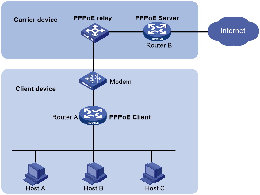
As shown in Figure 1, the PPPoE session is established between routers (Router A and Router B). All hosts share one PPPoE session for data transmission without being installed with PPPoE client software. This network structure is typically used by enterprises.
Figure 1 Router-initiated network structure
Host-initiated network structure
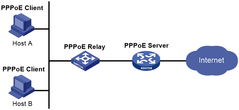
As shown in Figure 2, a PPPoE session is established between each host (PPPoE client) and the carrier router (PPPoE server). The service provider assigns an account to each host for billing and control. The host must be installed with PPPoE client software.
Figure 2 Host-initiated network structure
PPPoE relay fundamentals
The PPPoE relay controls protocol packet forwarding through monitoring the protocol packet exchange between the PPPoE client and the PPPoE server. Figure 3 shows the detailed process.
Figure 3 PPPoE client access procedure in a PPPoE relay network
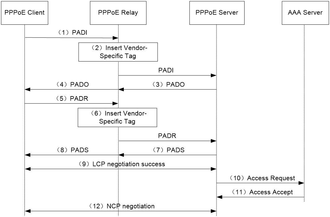
1. The PPPoE client broadcasts a PADI packet.
2. When receiving the PADI packet, the PPPoE relay adds the vendor-specific tag field to the PADI packet and broadcasts the packet out of all trusted ports.
The vendor-specific tag in a PPPoE packet identifies the location information (for example, the access port and VLANs) of a PPPoE client.
3. When receiving the PADI packets, the PPPoE server responds with a PADO packet to the PPPoE client.
4. When receiving the PADO packet, the PPPoE relay forwards the packet to the PPPoE client.
5. When receiving the PADO packet, the PPPoE client unicasts a PADR packet to the PPPoE server to apply for the PPPoE service.
6. When receiving the PADR packet, the PPPoE relay adds the vendor-specific tag to the packet and searches for an outgoing interface based on the destination MAC address of the PADR packet.
¡ If the outgoing interface is a trusted port, the PPPoE relay forwards the packet out of the port.
¡ If the outgoing interface is an untrusted port, the PPPoE relay drops the PADR packet.
7. When receiving the PADR packet, the PPPoE server assigns a session ID to the PPPoE client and binds the session ID to the vendor-specific tag. Then, the PPPoE server responds with a PADS packet to the PPPoE client.
8. When receiving the PADS packet, the PPPoE relay forwards the packet to the PPPoE client.
9. When receiving the PADS packet, the PPPoE client starts the LCP negotiation and authentication with the PPPoE server.
10. During the authentication phase, the PPPoE server will send the location information, username, and password of the PPPoE client to the RADIUS server for authentication.
11. The RADIUS server compares the location information, username, and password saved in the database with those of the PPPoE client. If they match, the PPPoE client passes the authentication.
12. After the PPPoE client passes authentication, the PPPoE client starts NCP negotiation with the PPPoE server. After the NCP negotiation succeeds, the PPPoE client successfully comes online.
Protocols and standards
RFC 2516: A Method for Transmitting PPP Over Ethernet (PPPoE)
Restrictions and guidelines for PPPoE
The device can act as a PPPoE relay.
The PPPoE relay supports the following interface views:
· Layer 2 Ethernet interface view
· Layer 2 aggregate interface view
Configuring the PPPoE relay
PPPoE relay tasks at a glance
To configure the PPPoE relay, perform the following tasks:
1. Enabling the PPPoE relay function
2. Configuring PPPoE relay trusted ports
3. (Optional.) Enabling an interface to strip the vendor-specific tags of the PPPoE server-side packets
4. (Optional.) Configuring the circuit ID and remote ID padding formats for the client-side PPPoE packets on the PPPoE relay
5. (Optional.) Configuring the vendor-specific tag processing policy for the client-side PPPoE packets on the PPPoE relay
Enabling the PPPoE relay function
About this task
For the PPPoE relay-related configurations to take effect, you must enable the PPPoE relay function.
Procedure
1. Enter system view.
system-view
2. Enable the PPPoE relay function.
pppoe-relay enable
By default, the PPPoE relay function is disabled.
Configuring PPPoE relay trusted ports
About this task
A PPPoE relay-enabled device processes PPPoE protocol packets as follows:
· When receiving PADI, PADR, and PADT on untrusted ports, the device can forward the packets out of only the trusted ports.
· When receiving PADO and PADS packets on untrusted ports, the device directly drops the packets.
· When receiving PADO, PADS, and PADT packets on trusted ports, the device can forward the packets out of any port.
· When receiving PADI and PADR packets on trusted ports, the device can forward the packets out of only the trusted ports.
For a PPPoE relay to correctly forward and process PPPoE protocol packets, you must configure the PPPoE server-facing interfaces on the PPPoE relay as trusted ports, and configure the PPPoE client-facing interfaces on the PPPoE relay as untrusted ports.
Restrictions and guidelines
This command is not supported on Layer 2 aggregation group member ports. If a Layer 2 Ethernet interface is configured with this command before joining a Layer 2 aggregation group, the command is cleared on the member port after the member port joins the aggregation group.
Procedure
1. Enter system view.
system-view
2. Enter Layer 2 Ethernet interface view.
interface interface-type interface-number
3. Configure the interface as a PPPoE relay trusted port.
pppoe-relay trust
By default, an interface is not configured as a PPPoE relay trusted port.
Enabling an interface to strip the vendor-specific tags of the PPPoE server-side packets
About this task
When the PPPoE relay receives PADO and PADS packets from the PPPoE server on a PPPoE relay trusted port with this feature enabled, the PPPoE relay strips the vendor-specific tags of the packets before forwarding the packets.
Restrictions and guidelines
This feature takes effect only on packets received on PPPoE relay trusted ports.
This command is not supported on Layer 2 aggregation group member ports. If a Layer 2 Ethernet interface is configured with this command before joining a Layer 2 aggregation group, the command is cleared on the member port after the member ports joins the aggregation group.
Procedure
1. Enter system view.
system-view
2. Enter Layer 2 Ethernet interface view.
interface interface-type interface-number
3. Enable the interface to strip the vendor-specific tags of the PPPoE server-side packets.
pppoe-relay server-information vendor-specific strip
By default, the function of stripping vendor-specific tags of the PPPoE server-side packets is disabled.
Configuring the circuit ID and remote ID padding formats for the client-side PPPoE packets on the PPPoE relay
About this task
When the PPPoE relay receives PPPoE packets from the PPPoE client, the PPPoE relay pads the circuit ID and remote ID with the contents in the format configured by using this command.
Both the circuit ID and remote ID are of up to 63 characters. When the content to be padded exceeds 63 characters, the first 63 characters are padded.
Procedure
1. Enter system view.
system-view
2. Configure the circuit ID and remote ID padding formats for the client-side PPPoE packets on the PPPoE relay.
pppoe-relay client-information format { circuit-id | remote-id } { ascii | hex | user-defined text }
By default, both the circuit ID padding format and the remote ID padding format for the client-side PPPoE packets are the ASCII string format on the PPPoE relay.
Configuring the vendor-specific tag processing policy for the client-side PPPoE packets on the PPPoE relay
About this task
When the PPPoE relay receives PADI or PADR packets, the PPPoE relay processes the packet according to whether the packets carry the vendor-specific tag and the configured vendor-specific tag processing policy. Then, the PPPoE relay sends the packets to the PPPoE server. Table 1 shows the detailed process.
Table 1 Vendor-specific tag processing policy on the PPPoE relay
|
Whether the received packets carry the vendor-specific tag |
Vendor-specific tag processing policy |
Processing for packets on the PPPoE relay |
|
The received packets carry vendor-specific tag |
Drop |
Strips the vendor-specific tag and then forwards the packets. |
|
Keep |
Keeps the vendor-specific tag unchanged and forwards the packets. |
|
|
Replace |
Pads the vendor-specific tag in the configured format, replaces the original vendor-specific tag with the new vendor-specific tag, and forwards the packets. |
|
|
The received packets do not carry vendor-specific tag |
Drop |
Directly forwards the packets. |
|
Keep |
Directly forwards the packets. |
|
|
Replace |
Pads the vendor-specific tag in the configured format, adds the new vendor-specific tag to the packets, and forwards the packets. |
Restrictions and guidelines
This feature can be configured both in system view and in interface view. The configuration in system view takes effect on all interfaces. The configuration in interface view takes effect only on the current interface. The configuration in interface view takes precedence over the configuration in system view.
The processing policy takes effect only on incoming packets of interfaces.
This command is not supported on Layer 2 aggregation group member ports. If a Layer 2 Ethernet interface is configured with this command before joining a Layer 2 aggregation group, the command is cleared on the member port after the member ports joins the aggregation group.
Configuring the global vendor-specific tag processing policy for the client-side PADI and PADR packets on the PPPoE relay
1. Enter system view.
system-view
2. Configure the global vendor-specific tag processing policy for the client-side PADI and PADR packets on the PPPoE relay.
pppoe-relay client-information strategy { drop | keep | replace }
By default, the global vendor-specific tag processing policy for the client-side PADI and PADR packets on the PPPoE relay is replace.
Configuring an interface-level vendor-specific tag processing policy for the client-side PADI and PADR packets on the PPPoE relay
1. Enter system view.
system-view
2. Enter Layer 2 Ethernet interface view.
interface interface-type interface-number
3. Configure the vendor-specific tag processing policy for the client-side PADI and PADR packets for the interface on the PPPoE relay.
pppoe-relay client-information strategy { drop | keep | replace }
By default, no vendor-specific tag processing policy for the client-side PADI and PADR packets is configured for an interface on the PPPoE relay.
Display and maintenance commands for PPPoE relay
Execute display commands in any view and reset commands in user view.
|
Task |
Command |
|
Display the vendor-specific tag processing configuration for client-side packets on the PPPoE relay. |
display pppoe-relay client-information { format | strategy } |
|
Display packet statistics for the PPPoE relay. |
display pppoe-relay statistics [ interface interface-type interface-number ] |
|
Clear packet statistics for the PPPoE relay. |
reset pppoe-relay statistics |
PPPoE configuration examples
Example: Configuring PPPoE relay
Network configuration
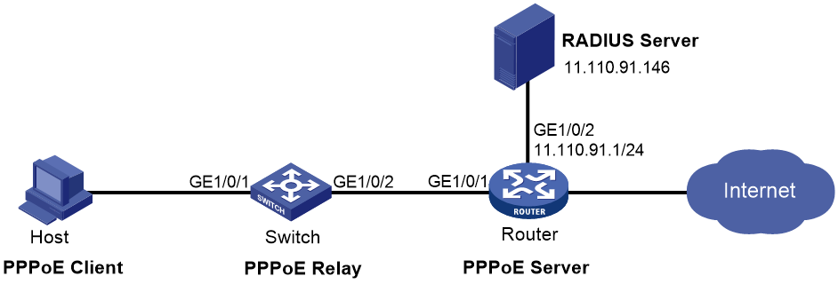
The host uses the PPPoE access method to connect to the router through the switch. The switch acts as the PPPoE relay. The router acts as the PPPoE server and assigns IPv4 addresses to the PPPoE client through a PPP address pool.
Figure 4 Network diagram
Procedure
1. Configure the switch as the PPPoE relay:
# Enable the PPPoE relay function.
<Switch> system-view
[Switch] pppoe-relay enable
# Configure the server-facing interface Ten-GigabitEthernet 1/0/2 as a PPPoE relay trusted port.
[Switch] interface Ten-GigabitEthernet 1/0/2
[Switch-Ten-GigabitEthernet1/0/2] pppoe-relay trust
2. Configure the router as a PPPoE server:
# Create a PPPoE user.
<Router> system-view
[Router] local-user user1 class network
[Router-luser-network-user1] password simple 123456TESTplat&!
[Router-luser-network-user1] service-type ppp
[Router-luser-network-user1] quit
# Configure Virtual-Template 1 to use CHAP for authentication and use a PPP address pool for IP address assignment. Set the DNS server IP address for the peer.
[Router] interface virtual-template 1
[Router-Virtual-Template1] ppp authentication-mode chap domain system
[Router-Virtual-Template1] ppp chap user user1
[Router-Virtual-Template1] remote address pool 1
[Router-Virtual-Template1] ppp ipcp dns 8.8.8.8
[Router-Virtual-Template1] quit
# Configure a PPP address pool that contains nine assignable IP addresses, and configure a gateway address for the PPP address pool.
[Router] ip pool 1 1.1.1.2 1.1.1.10
[Router] ip pool 1 gateway 1.1.1.1
# Enable the PPPoE server on Ten-GigabitEthernet 1/0/1, and bind the interface to Virtual-Template 1.
[Router] interface ten-gigabitethernet 1/0/1
[Router-Ten-GigabitEthernet1/0/1] pppoe-server bind virtual-template 1
[Router-Ten-GigabitEthernet1/0/1] quit
# Configure the default ISP domain (system) to use the RADIUS scheme for authentication, authorization, and accounting.
[Router] domain system
[Router-isp-system] authentication ppp radius-scheme rs1
[Router-isp-system] authorization ppp radius-scheme rs1
[Router-isp-system] accounting ppp radius-scheme rs1
[Router-isp-system] quit
# Configure a RADIUS scheme, and specify the primary authentication server and the primary accounting server.
[Router] radius scheme rs1
[Router-radius-rs1] primary authentication 11.110.91.146
[Router-radius-rs1] primary accounting 11.110.91.146
# Set the shared key for secure communication with the authentication and accounting servers to expert in plain text.
[Router-radius-rs1] key authentication simple expert
[Router-radius-rs1] key accounting simple expert
[Router-radius-rs1] quit
3. Configure the RADIUS server:
a. Configure the authentication and accounting passwords as expert.
b. Add a PPPoE user with username user1 and password 123456TESTplat&!.
For more information, see the user manual for the RADIUS server.
Verifying the configuration
Install the PPPoE client software and configure the username and password (user1 and 123456TESTplat&! in this example) on the hosts. Then, the hosts can use PPPoE to access the Internet through the router.
