- Table of Contents
-
- 11-Network Management and Monitoring Configuration Guide
- 00-Preface
- 01-System maintenance and debugging configuration
- 02-NQA configuration
- 03-NTP configuration
- 04-PTP configuration
- 05-SNMP configuration
- 06-RMON configuration
- 07-Event MIB configuration
- 08-NETCONF configuration
- 09-Puppet configuration
- 10-Chef configuration
- 11-CWMP configuration
- 12-EAA configuration
- 13-Process monitoring and maintenance configuration
- 14-Sampler configuration
- 15-Mirroring configuration
- 16-NetStream configuration
- 17-IPv6 NetStream configuration
- 18-sFlow configuration
- 19-Information center configuration
- 20-GOLD configuration
- 21-Packet capture configuration
- 22-VCF fabric configuration
- 23-Ansible configuration
- Related Documents
-
| Title | Size | Download |
|---|---|---|
| 15-Mirroring configuration | 447.32 KB |
Contents
Restrictions and guidelines: Port mirroring configuration
Configuring local port mirroring
Restrictions and guidelines for local port mirroring configuration
Local port mirroring tasks at a glance
Creating a local mirroring group
Configuring local port mirroring group with multiple monitoring devices
Configuring Layer 2 remote port mirroring
Restrictions and guidelines for Layer 2 remote port mirroring configuration
Layer 2 remote port mirroring with reflector port configuration task list
Layer 2 remote port mirroring with egress port configuration task list
Creating a remote destination group
Configuring the remote probe VLAN
Assigning the monitor port to the remote probe VLAN
Creating a remote source group
Configuring the reflector port
Configuring Layer 3 remote port mirroring
Restrictions and guidelines for Layer 3 remote port mirroring configuration
Layer 3 remote port mirroring tasks at a glance
Prerequisites for Layer 3 remote port mirroring
Configuring local mirroring groups
Display and maintenance commands for port mirroring
Port mirroring configuration examples
Example: Configuring local port mirroring (in source port mode)
Example: Configuring local port mirroring (in source CPU mode)
Example: Configuring local port mirroring with multiple monitoring devices
Example: Configuring Layer 2 remote port mirroring (with reflector port)
Example: Configuring Layer 2 remote port mirroring (with egress port)
Example: Configuring Layer 3 remote port mirroring
Types of flow-mirroring traffic to an interface
Restrictions and guidelines: Flow mirroring configuration
Flow mirroring tasks at a glance
Configuring a traffic behavior
Applying a QoS policy to an interface
Applying a QoS policy to a VLAN
Applying a QoS policy globally
Applying a QoS policy to the control plane
Display and maintenance commands for flow mirroring
Flow mirroring configuration examples
Example: Configuring flow mirroring
Configuring port mirroring
About port mirroring
Port mirroring copies the packets passing through a port or CPU to a port that connects to a data monitoring device for packet analysis.
Terminology
The following terms are used in port mirroring configuration.
Mirroring source
The mirroring sources can be one or more monitored ports (called source ports) or CPUs (called source CPUs).
Packets passing through mirroring sources are copied to a port connecting to a data monitoring device for packet analysis. The copies are called mirrored packets.
Source device
The device where the mirroring sources reside is called a source device.
Mirroring destination
The mirroring destination connects to a data monitoring device and is the destination port (also known as the monitor port) of mirrored packets. Mirrored packets are sent out of the monitor port to the data monitoring device.
A monitor port might receive multiple copies of a packet when it monitors multiple mirroring sources. For example, two copies of a packet are received on Port A when the following conditions exist:
· Port A is monitoring bidirectional traffic of Port B and Port C on the same device.
· The packet travels from Port B to Port C.
Destination device
The device where the monitor port resides is called the destination device.
Mirroring direction
The mirroring direction specifies the direction of the traffic that is copied on a mirroring source.
· Inbound—Copies packets received.
· Outbound—Copies packets sent.
· Bidirectional—Copies packets received and sent.
Mirroring group
Port mirroring is implemented through mirroring groups. Mirroring groups can be classified into local mirroring groups, remote source groups, and remote destination groups.
Reflector port, egress port, and remote probe VLAN
Reflector ports, remote probe VLANs, and egress ports are used for Layer 2 remote port mirroring. The remote probe VLAN is a dedicated VLAN for transmitting mirrored packets to the destination device. Both the reflector port and egress port reside on a source device and send mirrored packets to the remote probe VLAN.
On port mirroring devices, all ports except source, destination, reflector, and egress ports are called common ports.
Port mirroring classification
Port mirroring can be classified into local port mirroring and remote port mirroring.
· Local port mirroring—The source device is directly connected to a data monitoring device. The source device also acts as the destination device and forwards mirrored packets directly to the data monitoring device.
· Remote port mirroring—The source device is not directly connected to a data monitoring device. The source device sends mirrored packets to the destination device, which forwards the packets to the data monitoring device. Remote port mirroring can be further classified into Layer 2 and Layer 3 remote port mirroring:
¡ Layer 2 remote port mirroring—The source device and destination device are on the same Layer 2 network.
¡ Layer 3 remote port mirroring—The source device and destination device are separated by IP networks.
Local port mirroring
Figure 1 Local port mirroring implementation
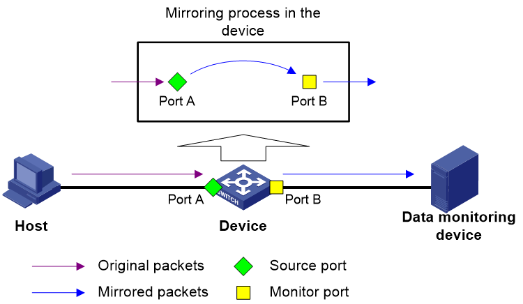
As shown in Figure 1, the source port (Port A) and the monitor port (Port B) reside on the same device. Packets received on Port A are copied to Port B. Port B then forwards the packets to the data monitoring device for analysis.
Layer 2 remote port mirroring
In Layer 2 remote port mirroring, the mirroring sources and destination reside on different devices and are in different mirroring groups.
A remote source group is a mirroring group that contains the mirroring sources. A remote destination group is a mirroring group that contains the mirroring destination. Intermediate devices are the devices between the source device and the destination device.
Layer 2 remote port mirroring can be implemented through the reflector port method or the egress port method.
Reflector port method
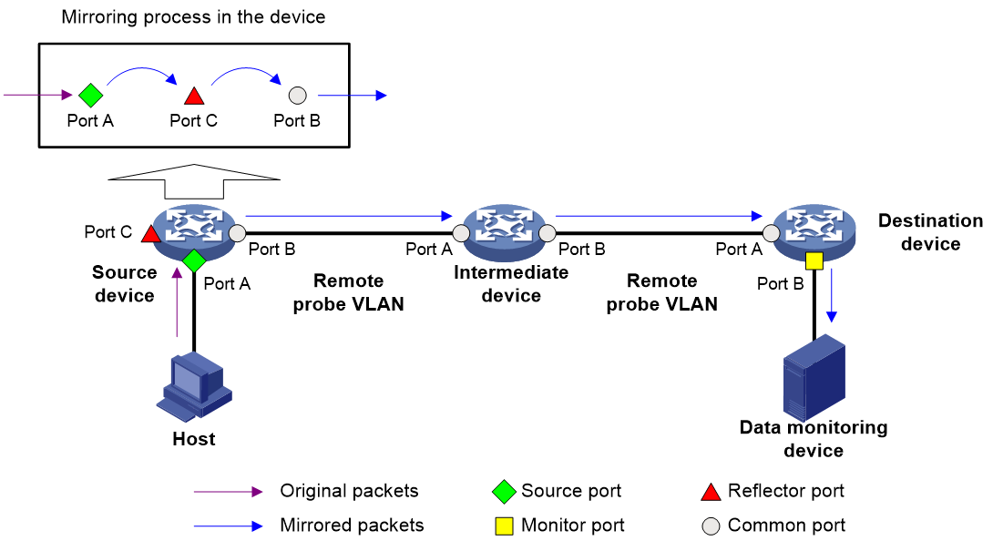
In Layer 2 remote port mirroring that uses the reflector port method, packets are mirrored as follows:
1. The source device copies packets received on the mirroring sources to the reflector port.
2. The reflector port broadcasts the mirrored packets in the remote probe VLAN.
3. The intermediate devices transmit the mirrored packets to the destination device through the remote probe VLAN.
4. Upon receiving the mirrored packets, the destination device determines whether the ID of the mirrored packets is the same as the remote probe VLAN ID. If the two VLAN IDs match, the destination device forwards the mirrored packets to the data monitoring device through the monitor port.
Figure 2 Layer 2 remote port mirroring implementation through the reflector port method
Egress port method
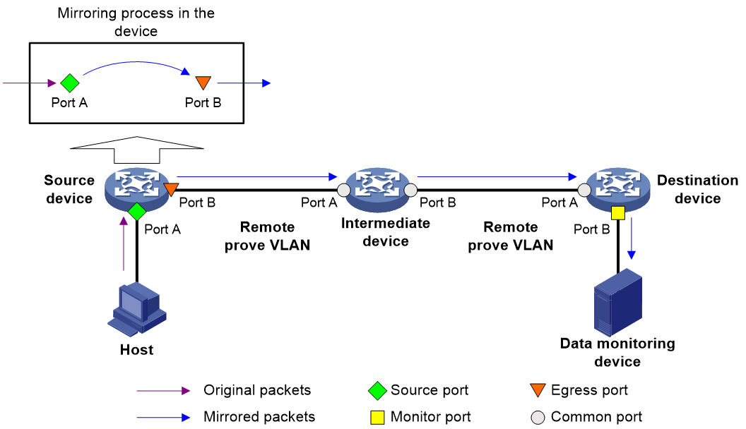
In Layer 2 remote port mirroring that uses the egress port method, packets are mirrored as follows:
1. The source device copies packets received on the mirroring sources to the egress port.
2. The egress port forwards the mirrored packets to the intermediate devices.
3. The intermediate devices flood the mirrored packets in the remote probe VLAN and transmit the mirrored packets to the destination device.
4. Upon receiving the mirrored packets, the destination device determines whether the ID of the mirrored packets is the same as the remote probe VLAN ID. If the two VLAN IDs match, the destination device forwards the mirrored packets to the data monitoring device through the monitor port.
Figure 3 Layer 2 remote port mirroring implementation through the egress port method
Layer 3 remote port mirroring
Layer 3 remote port mirroring is implemented through configuring a local mirroring group on both the source device and the destination device.
Configure the mirroring sources and destination for the local mirroring groups on the source device and destination device as follows:
· On the source device:
¡ Configure the ports to be monitored as source ports.
¡ Configure the CPUs to be monitored as source CPUs.
¡ Configure the tunnel interface through which mirrored packets are forwarded to the destination device as the monitor port.
· On the destination device:
¡ Configure the physical port corresponding to the tunnel interface as the source port.
¡ Configure the port that connects to the data monitoring device as the monitor port.
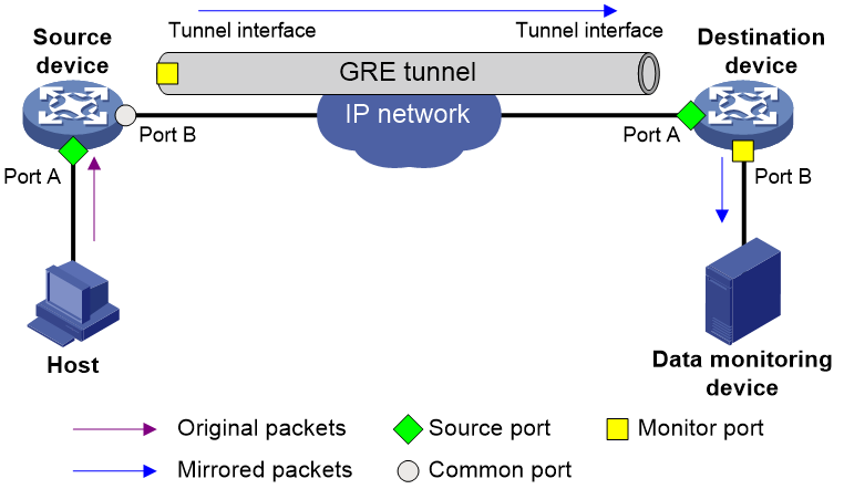
For example, in a network as shown in Figure 4, Layer 3 remote port mirroring works as follows:
1. The source device sends one copy of a packet received on the source port (Port A) to the tunnel interface.
The tunnel interface acts as the monitor port in the local mirroring group created on the source device.
2. The tunnel interface on the source device forwards the mirrored packet to the tunnel interface on the destination device through the GRE tunnel.
3. The destination device receives the mirrored packet from the physical interface of the tunnel interface.
The tunnel interface acts as the source port in the local mirroring group created on the destination device.
4. The physical interface of the tunnel interface sends one copy of the packet to the monitor port (Port B).
5. The monitor port (Port B) forwards the packet to the data monitoring device.
For more information about GRE tunnels and tunnel interfaces, see Layer 3—IP Services Configuration Guide.
Figure 4 Layer 3 remote port mirroring implementation
Restrictions and guidelines: Port mirroring configuration
The reflector port method for Layer 2 remote port mirroring can be used to implement local port mirroring with multiple data monitoring devices.
In the reflector port method, the reflector port broadcasts mirrored packets in the remote probe VLAN. By assigning the ports that connect to data monitoring devices to the remote probe VLAN, you can implement local port mirroring to mirror packets to multiple data monitoring devices. The egress port method cannot implement local port mirroring in this way.
For inbound traffic mirroring, the VLAN tag in the original packet is copied to the mirrored packet.
For outbound traffic mirroring, the mirrored packet carries the VLAN tag of the egress interface.
On an IRF fabric, mirrored packets will be forwarded between IRF member devices if the mirroring-related ports are not on the same IRF member device. In this case, the IRF links might be overloaded.
An interface configured with flow sampling cannot be configured as a source port of a mirroring group, and vice versa. For more information about sFlow, see "Configuring sFlow."
If an ACL, packet filter, or QoS policy is applied in the outbound direction globally or to an interface to match packets, the matching mirrored packets are also processed.
Configuring local port mirroring
Restrictions and guidelines for local port mirroring configuration
A local mirroring group takes effect only after it is configured with the monitor port and mirroring sources.
A local mirroring group supports multicard mirroring. The mirroring sources and destination can reside on different cards.
Local port mirroring tasks at a glance
To configure local port mirroring, perform the following tasks:
1. Configuring mirroring sources
Choose one of the following tasks:
2. Configuring the monitor port
Creating a local mirroring group
1. Enter system view.
system-view
2. Create a local mirroring group.
mirroring-group group-id local [ sampler sampler-name ]
Configuring mirroring sources
Restrictions and guidelines for mirroring source configuration
When you configure source ports for a local mirroring group, follow these restrictions and guidelines:
· A mirroring group can contain multiple source ports.
· A port can act as a source port for only one mirroring group.
· A source port cannot be configured as a reflector port, egress port, or monitor port.
· A Layer 2 or Layer 3 aggregate interface cannot be configured as a source port for a local mirroring group.
A local mirroring group can contain multiple source CPUs.
Configuring source ports
· Configure source ports in system view:
a. Enter system view.
system-view
b. Configure source ports for a local mirroring group.
mirroring-group group-id mirroring-port interface-list { both | inbound | outbound }
By default, no source port is configured for a local mirroring group.
· Configure source ports in interface view:
a. Enter system view.
system-view
b. Enter interface view.
interface interface-type interface-number
c. Configure the port as a source port for a local mirroring group.
mirroring-group group-id mirroring-port { both | inbound | outbound }
By default, a port does not act as a source port for any local mirroring groups.
Configuring source CPUs
1. Enter system view.
system-view
2. Configure source CPUs for a local mirroring group.
In standalone mode:
mirroring-group group-id mirroring-cpu slot slot-number-list { both | inbound | outbound }
In IRF mode:
mirroring-group group-id mirroring-cpu chassis chassis-number slot slot-number-list { both | inbound | outbound }
By default, no source CPU is configured for a local mirroring group.
The device supports mirroring only inbound traffic of a source CPU.
Configuring the monitor port
Restrictions and guidelines
Do not enable the spanning tree feature on the monitor port.
Multiple monitor ports can be specified for a local mirroring group.
For a Layer 2 aggregate interface configured as the monitor port of a mirroring group, do not configure its member ports as source ports of the mirroring group.
Use a monitor port only for port mirroring, so the data monitoring device receives only the mirrored traffic.
The member port of an aggregate interface cannot be configured as a monitor port.
Procedure
· Configure the monitor port in system view:
a. Enter system view.
system-view
b. Configure the monitor port for a local mirroring group.
mirroring-group group-id monitor-port interface-list
By default, no monitor port is configured for a local mirroring group.
· Configure the monitor port in interface view:
a. Enter system view.
system-view
b. Enter interface view.
interface interface-type interface-number
c. Configure the port as the monitor port for a mirroring group.
mirroring-group group-id monitor-port
By default, a port does not act as the monitor port for any local mirroring groups.
Configuring local port mirroring group with multiple monitoring devices
About local port mirroring with multiple monitoring devices
To monitor interesting traffic passing through a device on multiple directly connected data monitoring devices, configure local port mirroring with a remote probe VLAN as follows:
1. Configure a remote source group on the device.
2. Configure mirroring sources and a reflector port for the remote source group.
3. Specify a VLAN as the remote probe VLAN and assign the ports connecting to the data monitoring devices to the VLAN.
This configuration enables the device to copy packets received on the mirroring sources to the reflector port, which broadcasts the packets in the remote probe VLAN. The packets are then sent out of the member ports of the remote probe VLAN to the data monitoring devices.
Restrictions and guidelines
The reflector port must be a port not in use. Do not connect a network cable to the reflector port.
When a port is configured as a reflector port, the port restores to the factory default settings. You cannot configure other features on the reflector port.
Do not assign a source port of a mirroring group to the remote probe VLAN of the mirroring group.
A VLAN can act as the remote probe VLAN for only one remote source group. As a best practice, use the VLAN for port mirroring exclusively. Do not create a VLAN interface for the VLAN or configure other features for the VLAN.
The remote probe VLAN must be a static VLAN.
To delete a VLAN that has been configured as the remote probe VLAN for a mirroring group, remove the remote probe VLAN from the mirroring group first.
Procedure
1. Enter system view.
system-view
2. Create a remote source group.
mirroring-group group-id remote-source
3. Configure mirroring sources for the remote source group. Choose one option as needed:
¡ Configure mirroring ports in system view.
mirroring-group group-id mirroring-port interface-list { both | inbound | outbound }
¡ Execute the following commands in sequence to enter interface view and then configure the interface as a source port.
interface interface-type interface-number
mirroring-group group-id mirroring-port { both | inbound | outbound }
quit
4. Configure the reflector port for the remote source group.
mirroring-group group-id reflector-port reflector-port
By default, no reflector port is configured for a remote source group.
5. Create a VLAN and enter its view.
vlan vlan-id
6. Assign the ports that connect to the data monitoring devices to the VLAN.
port interface-list
By default, a VLAN does not contain any ports.
7. Return to system view.
quit
8. Specify the VLAN as the remote probe VLAN for the remote source group.
mirroring-group group-id remote-probe vlan vlan-id
By default, no remote probe VLAN is configured for a remote source group.
Configuring Layer 2 remote port mirroring
Restrictions and guidelines for Layer 2 remote port mirroring configuration
To ensure successful traffic mirroring, configure devices in the order of the destination device, the intermediate devices, and the source device.
If intermediate devices exist, configure the intermediate devices to allow the remote probe VLAN to pass through.
For a mirrored packet to successfully arrive at the remote destination device, make sure its VLAN ID is not removed or changed.
Do not configure both MVRP and Layer 2 remote port mirroring. Otherwise, MVRP might register the remote probe VLAN with incorrect ports, which would cause the monitor port to receive undesired copies. For more information about MVRP, see Layer 2—LAN Switching Configuration Guide.
You can mirror the bidirectional traffic of a source port only in the following situations:
· The source and destination devices are directly connected and they are both of the current device series.
· The source and destination devices are both of the current device series and MAC address learning is disabled for the remote probe VLAN on the intermediate devices.
· Only the source device is of the current device series and MAC address learning is disabled for the remote probe VLAN on the intermediate devices and the destination device.
If MAC address learning cannot be disabled for a VLAN on a device, disable MAC address learning on the ingress port of the mirrored traffic. A port can only forward mirrored traffic after you disable MAC address learning on the port.
Layer 2 remote port mirroring with reflector port configuration task list
Configuring the destination device
1. Creating a remote destination group
2. Configuring the monitor port
3. Configuring the remote probe VLAN
4. Assigning the monitor port to the remote probe VLAN
Configuring the source device
1. Creating a remote source group
2. Configuring mirroring sources
Choose one of the following tasks:
3. Configuring the reflector port
4. Configuring the remote probe VLAN
Layer 2 remote port mirroring with egress port configuration task list
Configuring the destination device
1. Creating a remote destination group
2. Configuring the monitor port
3. Configuring the remote probe VLAN
4. Assigning the monitor port to the remote probe VLAN
Configuring the source device
1. Creating a remote source group
2. Configuring mirroring sources
Choose one of the following tasks:
3. Configuring the egress port
4. Configuring the remote probe VLAN
Creating a remote destination group
Restrictions and guidelines
Perform this task on the destination device only.
Procedure
1. Enter system view.
system-view
2. Create a remote destination group.
mirroring-group group-id remote-destination [ sampler sampler-name ]
Configuring the monitor port
Restrictions and guidelines for monitor port configuration
Perform this task on the destination device only.
Do not enable the spanning tree feature on the monitor port.
Multiple monitor ports can be specified for a remote destination group.
For a Layer 2 aggregate interface configured as the monitor port of a mirroring group, do not configure its member ports as source ports of the mirroring group.
Use a monitor port only for port mirroring, so the data monitoring device receives only the mirrored traffic.
A monitor port can belong to only one mirroring group.
An aggregation group member port cannot be configured as the monitor port for a mirroring group.
Configuring the monitor port in system view
1. Enter system view.
system-view
2. Configure the monitor port for a remote destination group.
mirroring-group group-id monitor-port interface-list
By default, no monitor port is configured for a remote destination group.
Configuring the monitor port in interface view
1. Enter system view.
system-view
2. Enter interface view.
interface interface-type interface-number
3. Configure the port as the monitor port for a remote destination group.
mirroring-group group-id monitor-port
By default, a port does not act as the monitor port for any remote destination groups.
Configuring the remote probe VLAN
Restrictions and guidelines
This task is required on the both the source and destination devices.
Only an existing static VLAN can be configured as a remote probe VLAN.
When a VLAN is configured as a remote probe VLAN, use the remote probe VLAN for port mirroring exclusively.
Configure the same remote probe VLAN for the remote source group and the remote destination group.
Procedure
1. Enter system view.
system-view
2. Configure the remote probe VLAN for the remote source or destination group.
mirroring-group group-id remote-probe vlan vlan-id
By default, no remote probe VLAN is configured for a remote source or destination group.
Assigning the monitor port to the remote probe VLAN
Restrictions and guidelines
Perform this task on the destination device only.
Procedure
1. Enter system view.
system-view
2. Enter the interface view of the monitor port.
interface interface-type interface-number
3. Assign the port to the remote probe VLAN.
¡ Assign an access port to the remote probe VLAN.
port access vlan vlan-id
¡ Assign a trunk port to the remote probe VLAN.
port trunk permit vlan vlan-id
¡ Assign a hybrid port to the remote probe VLAN.
port hybrid vlan vlan-id { tagged | untagged }
For more information about the port access vlan, port trunk permit vlan, and port hybrid vlan commands, see Layer 2—LAN Switching Command Reference.
Creating a remote source group
Restrictions and guidelines
Perform this task on the source device only.
Procedure
1. Enter system view.
system-view
2. Create a remote source group.
mirroring-group group-id remote-source [ sampler sampler-name ]
Configuring mirroring sources
Restrictions and guidelines for mirroring source configuration
Perform this task on the source device only.
When you configure source ports for a remote source group, follow these restrictions and guidelines:
· Do not assign a source port of a mirroring group to the remote probe VLAN of the mirroring group.
· A mirroring group can contain multiple source ports.
· A port can act as a source port for only one mirroring group.
· A source port cannot be configured as a reflector port, monitor port, or egress port.
· A Layer 2 or Layer 3 aggregate interface cannot be configured a source port.
A mirroring group can contain multiple source CPUs.
Configuring source ports
· Configure source ports in system view:
a. Enter system view.
system-view
b. Configure source ports for a remote source group.
mirroring-group group-id mirroring-port interface-list { both | inbound | outbound }
By default, no source port is configured for a remote source group.
· Configure source ports in interface view:
a. Enter system view.
system-view
b. Enter interface view.
interface interface-type interface-number
c. Configure the port as a source port for a remote source group.
mirroring-group group-id mirroring-port { both | inbound | outbound }
By default, a port does not act as a source port for any remote source groups.
Configuring source CPUs
1. Enter system view.
system-view
2. Configure source CPUs for a remote source group.
In standalone mode:
mirroring-group group-id mirroring-cpu slot slot-number-list inbound
In IRF mode:
mirroring-group group-id mirroring-cpu chassis chassis-number slot slot-number-list inbound
By default, no source CPU is configured for a remote source group.
The device supports mirroring only inbound traffic of a source CPU.
Configuring the reflector port
Restrictions and guidelines for reflector port configuration
Perform this task on the source device only.
A remote source group supports only one reflector port.
Configuring the reflector port in system view
1. Enter system view.
system-view
2. Configure the reflector port for a remote source group.
mirroring-group group-id reflector-port interface-type interface-number
|
|
CAUTION: · The port to be configured as a reflector port must be a port not in use. Do not connect a network cable to a reflector port. · When a port is configured as a reflector port, the port restores to the factory default settings. You cannot configure other features on a reflector port. · If an IRF port is bound to only one physical interface, do not configure the physical interface as a reflector port. Otherwise, the IRF might split. |
By default, no reflector port is configured for a remote source group.
Configuring the reflector port in interface view
1. Enter system view.
system-view
2. Enter interface view.
interface interface-type interface-number
3. Configure the port as the reflector port for a remote source group.
mirroring-group group-id reflector-port
|
|
CAUTION: · The port to be configured as a reflector port must be a port not in use. Do not connect a network cable to a reflector port. · When a port is configured as a reflector port, the port restores to the factory default settings. You cannot configure other features on a reflector port. · If an IRF port is bound to only one physical interface, do not configure the physical interface as a reflector port. Otherwise, the IRF might split. |
By default, a port does not act as the reflector port for any remote source groups.
Configuring the egress port
Restrictions and guidelines for egress port configuration
Perform this task on the source device only.
Disable the following features on the egress port:
· Spanning tree.
· 802.1X.
· IGMP snooping.
· Static ARP.
· MAC address learning.
A port of an existing mirroring group cannot be configured as an egress port.
A mirroring group supports only one egress port.
Configuring the egress port in system view
1. Enter system view.
system-view
2. Configure the egress port for a remote source group.
mirroring-group group-id monitor-egress interface-type interface-number
By default, no egress port is configured for a remote source group.
3. Enter the egress port view.
interface interface-type interface-number
4. Assign the egress port to the remote probe VLAN.
¡ Assign a trunk port to the remote probe VLAN.
port trunk permit vlan vlan-id
¡ Assign a hybrid port to the remote probe VLAN.
port hybrid vlan vlan-id { tagged | untagged }
For more information about the port trunk permit vlan and port hybrid vlan commands, see Layer 2—LAN Switching Command Reference.
Configuring the egress port in interface view
1. Enter system view.
system-view
2. Enter interface view.
interface interface-type interface-number
3. Configure the port as the egress port for a remote source group.
mirroring-group group-id monitor-egress
By default, a port does not act as the egress port for any remote source groups.
Configuring Layer 3 remote port mirroring
Restrictions and guidelines for Layer 3 remote port mirroring configuration
To implement Layer 3 remote port mirroring, you must configure a unicast routing protocol on the intermediate devices to ensure Layer 3 reachability between the source and destination devices.
On an IRF fabric with the mirroring source ports and monitor port on different IRF member devices, the mirrored packets will be rate-limited if the monitor port is unreachable or the destination of the original packets is the local member device.
Layer 3 remote port mirroring tasks at a glance
Configuring the source device
1. Configuring local mirroring groups
2. Configuring mirroring sources
Choose one of the following tasks:
3. Configuring the monitor port
Configuring the destination device
1. Configuring local mirroring groups
2. Configuring mirroring sources
3. Configuring the monitor port
Prerequisites for Layer 3 remote port mirroring
Before configuring Layer 3 remote mirroring, complete the following tasks:
· Create a tunnel interface and a GRE tunnel.
· Configure the source and destination addresses of the tunnel interface as the IP addresses of the physical interfaces on the source and destination devices, respectively.
For more information about tunnel interfaces, see Layer 3—IP Services Configuration Guide.
On an IRF fabric, the mirrored packets are rate-limited when the following conditions exist:
· The mirroring source ports and monitor ports are not on the same IRF member device.
· The mirroring destination is unreachable or the destination of the original packets is the local device.
Configuring local mirroring groups
Restrictions and guidelines
Configure a local mirroring group on both the source device and the destination device.
Procedure
1. Enter system view.
system-view
2. Create a local mirroring group.
mirroring-group group-id local
Configuring mirroring sources
Restrictions and guidelines for mirroring source configuration
When you configure source ports for a local mirroring group, follow these restrictions and guidelines:
· On the source device, configure the ports you want to monitor as the source ports. On the destination device, configure the physical interface corresponding to the tunnel interface as the source port.
· A port can act as a source port for only one mirroring group.
· A source port cannot be configured as a reflector port, egress port, or monitor port.
· A Layer 2 or Layer 3 aggregate interface cannot be configured as a source port.
When you configure source CPUs for a local mirroring group, follow these restrictions and guidelines:
· Perform this task on the source device only.
· A mirroring group can contain multiple source CPUs.
Configuring source ports
· Configure source ports in system view:
a. Enter system view.
system-view
b. Configure source ports for a local mirroring group.
mirroring-group group-id mirroring-port interface-list { both | inbound | outbound }
By default, no source port is configured for a local mirroring group.
· Configure source ports in interface view:
a. Enter system view.
system-view
b. Enter interface view.
interface interface-type interface-number
c. Configure the port as a source port for a local mirroring group.
mirroring-group group-id mirroring-port { both | inbound | outbound }
By default, a port does not act as a source port for any local mirroring groups.
Configuring source CPUs
1. Enter system view.
system-view
2. Configure source CPUs for a local mirroring group.
In standalone mode:
mirroring-group group-id mirroring-cpu slot slot-number-list inbound
In IRF mode:
mirroring-group group-id mirroring-cpu chassis chassis-number slot slot-number-list inbound
By default, no source CPU is configured for a local mirroring group.
The device supports mirroring only the inbound traffic of a source CPU.
Configuring the monitor port
Restrictions and guidelines for monitor port configuration
On the source device, configure a tunnel interface as a monitor port. On the destination device, configure the port that connects to a data monitoring device as a monitor port.
On the source device, only one tunnel interface can be configured as the monitor port for a local mirroring group.
On the destination device, do not enable the spanning tree feature on the monitor port
On the destination device, multiple monitor ports can be specified for a local mirroring group.
Use a monitor port only for port mirroring, so the data monitoring device receives only the mirrored traffic.
An aggregation group member port cannot be configured as the monitor port for a mirroring group.
Procedure
· Configure the monitor port in system view:
a. Enter system view.
system-view
b. Configure the monitor port for a local mirroring group.
mirroring-group group-id monitor-port interface-list
By default, no monitor port is configured for a local mirroring group.
· Configure the monitor port in interface view:
a. Enter system view.
system-view
b. Enter interface view.
interface interface-type interface-number
c. Configure the port as the monitor port for a local mirroring group.
mirroring-group group-id monitor-port
By default, a port does not act as the monitor port for any local mirroring groups.
Display and maintenance commands for port mirroring
Execute display commands in any view.
|
Task |
Command |
|
Display mirroring group information. |
display mirroring-group { group-id | all | local | remote-destination | remote-source } |
Port mirroring configuration examples
Example: Configuring local port mirroring (in source port mode)
Network configuration
As shown in Figure 5, configure local port mirroring in source port mode to enable the server to monitor the bidirectional traffic of the two departments.

Procedure
|
|
IMPORTANT: By default, interfaces on the device are disabled (in ADM or Administratively Down state). To have an interface operate, you must use the undo shutdown command to enable that interface. |
# Create local mirroring group 1.
<Device> system-view
[Device] mirroring-group 1 local
# Configure FortyGigE 1/0/1 and FortyGigE 1/0/2 as source ports for local mirroring group 1.
[Device] mirroring-group 1 mirroring-port fortygige 1/0/1 fortygige 1/0/2 both
# Configure FortyGigE 1/0/3 as the monitor port for local mirroring group 1.
[Device] mirroring-group 1 monitor-port fortygige 1/0/3
# Disable the spanning tree feature on the monitor port (FortyGigE 1/0/3).
[Device] interface fortygige 1/0/3
[Device-FortyGigE1/0/3] undo stp enable
[Device-FortyGigE1/0/3] quit
Verifying the configuration
# Verify the mirroring group configuration.
[Device] display mirroring-group all
Mirroring group 1:
Type: Local
Status: Active
Mirroring port:
FortyGigE1/0/1 Both
FortyGigE1/0/2 Both
Monitor port: FortyGigE1/0/3
Example: Configuring local port mirroring (in source CPU mode)
Network configuration
As shown in Figure 6, FortyGigE 1/0/1 and FortyGigE 1/0/2 are located on the card in slot 1.
Configure local port mirroring in source CPU mode to enable the server to monitor all packets matching the following criteria:
· Received by the Marketing Department and the Technical Department.
· Processed by the CPU in slot 1 of the device.

Procedure
|
|
IMPORTANT: By default, interfaces on the device are disabled (in ADM or Administratively Down state). To have an interface operate, you must use the undo shutdown command to enable that interface. |
# Create local mirroring group 1.
<Device> system-view
[Device] mirroring-group 1 local
# Configure the CPU in slot 1 of the device as a source CPU for local mirroring group 1.
[Device] mirroring-group 1 mirroring-cpu slot 1 inbound
# Configure FortyGigE 1/0/3 as the monitor port for local mirroring group 1.
[Device] mirroring-group 1 monitor-port fortygige 1/0/3
# Disable the spanning tree feature on the monitor port (FortyGigE 1/0/3).
[Device] interface fortygige 1/0/3
[Device-FortyGigE1/0/3] undo stp enable
[Device-FortyGigE1/0/3] quit
Verifying the configuration
# Verify the mirroring group configuration.
[Device] display mirroring-group all
Mirroring group 1:
Type: Local
Status: Active
Mirroring CPU:
Slot 1 Inbound
Monitor port: FortyGigE1/0/3
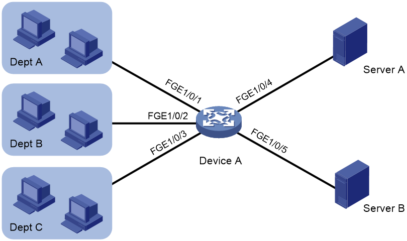
Example: Configuring local port mirroring with multiple monitoring devices
Network configuration
As shown in Figure 7, Dept. A, Dept. B, and Dept. C are connected to the device through FortyGigE 1/0/1, FortyGigE 1/0/2, and FortyGigE 1/0/3, respectively.
Configure port mirroring to enable data monitoring devices Server A and Server B to monitor both the incoming and outgoing traffic of departments A, B, and C.
Procedure
|
|
IMPORTANT: By default, interfaces on the device are disabled (in ADM or Administratively Down state). To have an interface operate, you must use the undo shutdown command to enable that interface. |
# Create remote source group 1.
<Device> system-view
[Device] mirroring-group 1 remote-source
# Configure FortyGigE 1/0/1 through FortyGigE 1/0/3 as source ports of remote source group 1.
[Device] mirroring-group 1 mirroring-port fortygige1/0/1 to fortygige1/0/3 both
# Configure an unused port (FortyGigE 1/0/6 in this example) as the reflector port of remote source group 1.
[Device] mirroring-group 1 reflector-port fortygige1/0/6
This operation may delete all settings made on the interface. Continue? [Y/N]:y
# Create VLAN 10 and assign the ports connecting the data monitoring devices to the VLAN.
[Device] vlan 10
[Device-vlan10] port fortygige1/0/4 to fortygige1/0/5
[Device-vlan10] quit
# Configure VLAN 10 as the remote probe VLAN of remote source group 1.
[Device] mirroring-group 1 remote-probe vlan 10
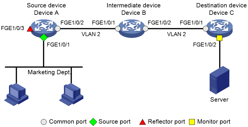
Example: Configuring Layer 2 remote port mirroring (with reflector port)
Network configuration
As shown in Figure 8, configure Layer 2 remote port mirroring to enable the server to monitor the inbound traffic of the Marketing Department.
Procedure
|
|
IMPORTANT: By default, interfaces on the device are disabled (in ADM or Administratively Down state). To have an interface operate, you must use the undo shutdown command to enable that interface. |
1. Configure Device C (the destination device):
# Configure FortyGigE 1/0/1 as a trunk port, and assign the port to VLAN 2.
<DeviceC> system-view
[DeviceC] interface fortygige 1/0/1
[DeviceC-FortyGigE1/0/1] port link-type trunk
[DeviceC-FortyGigE1/0/1] port trunk permit vlan 2
[DeviceC-FortyGigE1/0/1] quit
# Create a remote destination group.
[DeviceC] mirroring-group 2 remote-destination
# Create VLAN 2.
[DeviceC] vlan 2
# Configure VLAN 2 as the remote probe VLAN for the mirroring group.
[DeviceC] mirroring-group 2 remote-probe vlan 2
# Configure FortyGigE 1/0/2 as the monitor port for the mirroring group.
[DeviceC] interface fortygige 1/0/2
[DeviceC-FortyGigE1/0/2] mirroring-group 2 monitor-port
# Disable the spanning tree feature on FortyGigE 1/0/2.
[DeviceC-FortyGigE1/0/2] undo stp enable
# Assign FortyGigE 1/0/2 to VLAN 2.
[DeviceC-FortyGigE1/0/2] port access vlan 2
[DeviceC-FortyGigE1/0/2] quit
2. Configure Device B (the intermediate device):
# Create VLAN 2.
<DeviceB> system-view
[DeviceB] vlan 2
# Configure FortyGigE 1/0/1 as a trunk port, and assign the port to VLAN 2.
[DeviceB] interface fortygige 1/0/1
[DeviceB-FortyGigE1/0/1] port link-type trunk
[DeviceB-FortyGigE1/0/1] port trunk permit vlan 2
[DeviceB-FortyGigE1/0/1] quit
# Configure FortyGigE 1/0/2 as a trunk port, and assign the port to VLAN 2.
[DeviceB] interface fortygige 1/0/2
[DeviceB-FortyGigE1/0/2] port link-type trunk
[DeviceB-FortyGigE1/0/2] port trunk permit vlan 2
[DeviceB-FortyGigE1/0/2] quit
3. Configure Device A (the source device):
# Create a remote source group.
<DeviceA> system-view
[DeviceA] mirroring-group 1 remote-source
# Create VLAN 2.
[DeviceA] vlan 2
# Configure VLAN 2 as the remote probe VLAN for the mirroring group.
[DeviceA] mirroring-group 1 remote-probe vlan 2
# Configure FortyGigE 1/0/1 as a source port for the mirroring group.
[DeviceA] mirroring-group 1 mirroring-port fortygige 1/0/1 outbound
# Configure FortyGigE 1/0/3 as the reflector port for the mirroring group.
[DeviceA] mirroring-group 1 reflector-port fortygige 1/0/3
This operation may delete all settings made on the interface. Continue? [Y/N]: y
# Configure FortyGigE 1/0/2 as a trunk port, and assign the port to VLAN 2.
[DeviceA] interface fortygige 1/0/2
[DeviceA-FortyGigE1/0/2] port link-type trunk
[DeviceA-FortyGigE1/0/2] port trunk permit vlan 2
[DeviceA-FortyGigE1/0/2] quit
Verifying the configuration
# Verify the mirroring group configuration on Device C.
[DeviceC] display mirroring-group all
Mirroring group 2:
Type: Remote destination
Status: Active
Monitor port: FortyGigE1/0/2
Remote probe VLAN: 2
# Verify the mirroring group configuration on Device A.
[DeviceA] display mirroring-group all
Mirroring group 1:
Type: Remote source
Status: Active
Mirroring port:
FortyGigE1/0/1 Outbound
Reflector port: FortyGigE1/0/3
Remote probe VLAN: 2
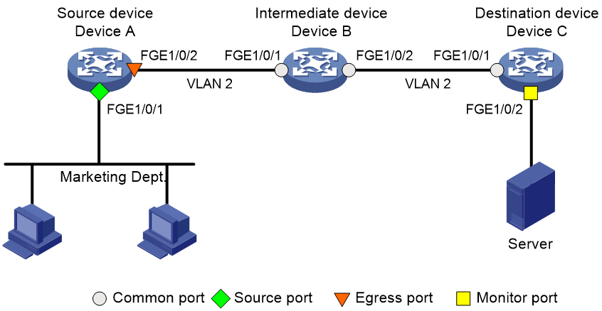
Example: Configuring Layer 2 remote port mirroring (with egress port)
Network configuration
On the Layer 2 network shown in Figure 9, configure Layer 2 remote port mirroring to enable the server to monitor the inbound traffic of the Marketing Department.
Procedure
|
|
IMPORTANT: By default, interfaces on the device are disabled (in ADM or Administratively Down state). To have an interface operate, you must use the undo shutdown command to enable that interface. |
1. Configure Device C (the destination device):
# Configure FortyGigE 1/0/1 as a trunk port, and assign the port to VLAN 2.
<DeviceC> system-view
[DeviceC] interface fortygige 1/0/1
[DeviceC-FortyGigE1/0/1] port link-type trunk
[DeviceC-FortyGigE1/0/1] port trunk permit vlan 2
[DeviceC-FortyGigE1/0/1] quit
# Create a remote destination group.
[DeviceC] mirroring-group 2 remote-destination
# Create VLAN 2.
[DeviceC] vlan 2
# Configure VLAN 2 as the remote probe VLAN for the mirroring group.
[DeviceC] mirroring-group 2 remote-probe vlan 2
# Configure FortyGigE 1/0/2 as the monitor port for the mirroring group.
[DeviceC] interface fortygige 1/0/2
[DeviceC-FortyGigE1/0/2] mirroring-group 2 monitor-port
# Disable the spanning tree feature on FortyGigE 1/0/2.
[DeviceC-FortyGigE1/0/2] undo stp enable
# Assign FortyGigE 1/0/2 to VLAN 2 as an access port.
[DeviceC-FortyGigE1/0/2] port access vlan 2
[DeviceC-FortyGigE1/0/2] quit
2. Configure Device B (the intermediate device):
# Create VLAN 2.
<DeviceB> system-view
[DeviceB] vlan 2
# Configure FortyGigE 1/0/1 as a trunk port, and assign the port to VLAN 2.
[DeviceB] interface fortygige 1/0/1
[DeviceB-FortyGigE1/0/1] port link-type trunk
[DeviceB-FortyGigE1/0/1] port trunk permit vlan 2
[DeviceB-FortyGigE1/0/1] quit
# Configure FortyGigE 1/0/2 as a trunk port, and assign the port to VLAN 2.
[DeviceB] interface fortygige 1/0/2
[DeviceB-FortyGigE1/0/2] port link-type trunk
[DeviceB-FortyGigE1/0/2] port trunk permit vlan 2
[DeviceB-FortyGigE1/0/2] quit
3. Configure Device A (the source device):
# Create a remote source group.
<DeviceA> system-view
[DeviceA] mirroring-group 1 remote-source
# Create VLAN 2.
[DeviceA] vlan 2
# Configure VLAN 2 as the remote probe VLAN of the mirroring group.
[DeviceA] mirroring-group 1 remote-probe vlan 2
# Configure FortyGigE 1/0/1 as a source port for the mirroring group.
[DeviceA] mirroring-group 1 mirroring-port fortygige 1/0/1 outbound
# Configure FortyGigE 1/0/2 as the egress port for the mirroring group.
[DeviceA] mirroring-group 1 monitor-egress fortygige 1/0/2
# Configure FortyGigE 1/0/2 as a trunk port, and assign the port to VLAN 2.
[DeviceA] interface fortygige 1/0/2
[DeviceA-FortyGigE1/0/2] port link-type trunk
[DeviceA-FortyGigE1/0/2] port trunk permit vlan 2
# Disable the spanning tree feature on the port.
[DeviceA-FortyGigE1/0/2] undo stp enable
[DeviceA-FortyGigE1/0/2] quit
Verifying the configuration
# Verify the mirroring group configuration on Device C.
[DeviceC] display mirroring-group all
Mirroring group 2:
Type: Remote destination
Status: Active
Monitor port: FortyGigE1/0/2
Remote probe VLAN: 2
# Verify the mirroring group configuration on Device A.
[DeviceA] display mirroring-group all
Mirroring group 1:
Type: Remote source
Status: Active
Mirroring port:
FortyGigE1/0/1 Outbound
Monitor egress port: FortyGigE1/0/2
Remote probe VLAN: 2
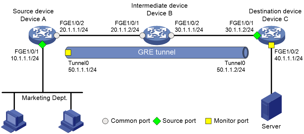
Example: Configuring Layer 3 remote port mirroring
Network configuration
On a Layer 3 network shown in Figure 10, configure Layer 3 remote port mirroring to enable the server to monitor the bidirectional traffic of the Marketing Department.
Procedure
|
|
IMPORTANT: By default, interfaces on the device are disabled (in ADM or Administratively Down state). To have an interface operate, you must use the undo shutdown command to enable that interface. |
1. Configure IP addresses for the tunnel interfaces and related ports on the devices. (Details not shown.)
2. Configure Device A (the source device):
# Create service loopback group 1 and specify the unicast tunnel service for the group.
<DeviceA> system-view
[DeviceA] service-loopback group 1 type tunnel
# Assign FortyGigE 1/0/3 to service loopback group 1.
[DeviceA] interface fortygige 1/0/3
[DeviceA-FortyGigE1/0/3] port service-loopback group 1
All configurations on the interface will be lost. Continue?[Y/N]:y
[DeviceA-FortyGigE1/0/3] quit
# Create tunnel interface Tunnel 0 that operates in GRE mode, and configure an IP address and subnet mask for the interface.
[DeviceA] interface tunnel 0 mode gre
[DeviceA-Tunnel0] ip address 50.1.1.1 24
# Configure source and destination IP addresses for Tunnel 0.
[DeviceA-Tunnel0] source 20.1.1.1
[DeviceA-Tunnel0] destination 30.1.1.2
[DeviceA-Tunnel0] quit
# Enable the OSPF protocol.
[DeviceA] ospf 1
[DeviceA-ospf-1] area 0
[DeviceA-ospf-1-area-0.0.0.0] network 10.1.1.0 0.0.0.255
[DeviceA-ospf-1-area-0.0.0.0] network 20.1.1.0 0.0.0.255
[DeviceA-ospf-1-area-0.0.0.0] quit
[DeviceA-ospf-1] quit
# Create local mirroring group 1.
[DeviceA] mirroring-group 1 local
# Configure FortyGigE 1/0/1 as a source port and Tunnel 0 as the monitor port of local mirroring group 1.
[DeviceA] mirroring-group 1 mirroring-port fortygige 1/0/1 both
[DeviceA] mirroring-group 1 monitor-port tunnel 0
3. Enable the OSPF protocol on Device B (the intermediate device).
<DeviceB> system-view
[DeviceB] ospf 1
[DeviceB-ospf-1] area 0
[DeviceB-ospf-1-area-0.0.0.0] network 20.1.1.0 0.0.0.255
[DeviceB-ospf-1-area-0.0.0.0] network 30.1.1.0 0.0.0.255
[DeviceB-ospf-1-area-0.0.0.0] quit
[DeviceB-ospf-1] quit
4. Configure Device C (the destination device):
# Create service loopback group 1 and specify the unicast tunnel service for the group.
<DeviceC> system-view
[DeviceC] service-loopback group 1 type tunnel
# Assign FortyGigE 1/0/3 to service loopback group 1.
[DeviceC] interface fortygige 1/0/3
[DeviceC-FortyGigE1/0/3] port service-loopback group 1
All configurations on the interface will be lost. Continue?[Y/N]:y
[DeviceC-FortyGigE1/0/3] quit
# Create tunnel interface Tunnel 0 that operates in GRE mode, and configure an IP address and subnet mask for the interface.
[DeviceC] interface tunnel 0 mode gre
[DeviceC-Tunnel0] ip address 50.1.1.2 24
# Configure source and destination IP addresses for Tunnel 0.
[DeviceC-Tunnel0] source 30.1.1.2
[DeviceC-Tunnel0] destination 20.1.1.1
[DeviceC-Tunnel0] quit
# Enable the OSPF protocol.
[DeviceC] ospf 1
[DeviceC-ospf-1] area 0
[DeviceC-ospf-1-area-0.0.0.0] network 30.1.1.0 0.0.0.255
[DeviceC-ospf-1-area-0.0.0.0] network 40.1.1.0 0.0.0.255
[DeviceC-ospf-1-area-0.0.0.0] quit
[DeviceC-ospf-1] quit
# Create local mirroring group 1.
[DeviceC] mirroring-group 1 local
# Configure FortyGigE 1/0/1 as a source port for local mirroring group 1.
[DeviceC] mirroring-group 1 mirroring-port fortygige 1/0/1 inbound
# Configure FortyGigE 1/0/2 as the monitor port for local mirroring group 1.
[DeviceC] mirroring-group 1 monitor-port fortygige 1/0/2
Verifying the configuration
# Verify the mirroring group configuration on Device A.
[DeviceA] display mirroring-group all
Mirroring group 1:
Type: Local
Status: Active
Mirroring port:
FortyGigE1/0/1 Both
Monitor port: Tunnel0
# Display information about all mirroring groups on Device C.
[DeviceC] display mirroring-group all
Mirroring group 1:
Type: Local
Status: Active
Mirroring port:
FortyGigE1/0/1 Inbound
Configuring flow mirroring
About flow mirroring
Flow mirroring copies packets matching a class to a destination for packet analyzing and monitoring. It is implemented through QoS.
To implement flow mirroring through QoS, perform the following tasks:
· Define traffic classes and configure match criteria to classify packets to be mirrored. Flow mirroring allows you to flexibly classify packets to be analyzed by defining match criteria.
· Configure traffic behaviors to mirror the matching packets to the specified destination.
You can configure an action to mirror the matching packets to one of the following destinations:
· Interface—The matching packets are copied to an interface and then forwarded to a data monitoring device for analysis.
· Monitoring group—The matching packets are copied to all the member interfaces of a monitoring group and then forwarded to the data monitoring devices directly connected to the interfaces.
· (In standalone mode.) (In IRF mode.) CPU—The matching packets are copied to the CPU of the card where they are received. The CPU analyzes the packets or delivers them to upper layers.
For more information about QoS policies, traffic classes, and traffic behaviors, see ACL and QoS Configuration Guide.
Types of flow-mirroring traffic to an interface
Depending on whether the mirroring source and mirroring destination are on the same device, flow-mirroring traffic to an interface includes the following types:
· Flow mirroring SPAN—Flow-mirrors traffic to a local interface.
· Flow mirroring RSPAN—Flow-mirrors traffic to an interface, and then forwards traffic to a remote Layer 2 interface based on the VLAN of the mirrored traffic or through QoS traffic redirecting.
· Flow mirroring ERSPAN—Encapsulates traffic in GRE packets with protocol number 0x88BE and routes the traffic to a remote monitoring device at Layer 3.
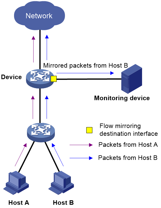
Flow mirroring SPAN or RSPAN
For flow mirroring SPAN, configure a QoS policy on the source device. Configure the QoS policy as follows:
1. Configure a traffic class to match packets.
2. Configure a traffic behavior to flow-mirror traffic to an interface without specifying the loopback, destination-ip, or source-ip keyword.
3. Associate the traffic class with the traffic behavior.
When the device receives a matching packet, the device sends one copy of the packet to the interface specified by the traffic behavior. The interface forwards the mirrored packet to the monitoring device.
Figure 11 Flow mirroring SPAN
To implement RSPAN, forward the mirrored packet to a remote Layer 2 interface based on the VLAN of the mirrored packet or through QoS traffic redirecting.
Flow mirroring ERSPAN
Flow mirroring ERSPAN can be implemented in loopback mode, encapsulation parameter mode, or monitoring group mode.
On all devices from source to destination, configure a unicast routing protocol to ensure Layer 3 reachability between the devices.
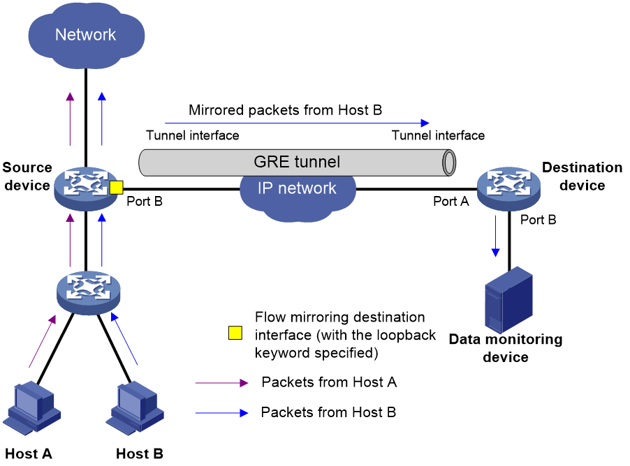
Loopback mode
As shown in Figure 12, configure flow mirroring ERSPAN in loopback mode as follows:
1. On the source device, apply a QoS policy to the source interface as follows:
a. Configure a traffic class to match packets.
b. Configure a traffic behavior to mirror packets to Port B and specify the loopback keyword.
c. Create a QoS policy, and associate the traffic class with the traffic behavior.
d. Apply the QoS policy to the source interface.
2. On the source device, apply a QoS policy to Port B as follows:
a. Configure a traffic class to match packets.
b. Configure a traffic behavior to redirect packets to a tunnel interface.
c. Create a QoS policy, and associate the traffic class with the traffic behavior.
d. Apply the QoS policy to Port B.
3. The destination device receives mirrored packets on the tunnel interface and decapsulates the packets. Then, the destination device forwards the packets based on the destination IP address of the original packets.
Make sure the destination device has the route and ARP entry to the destination IP address.
Figure 12 Flow mirroring ERSPAN in loopback mode
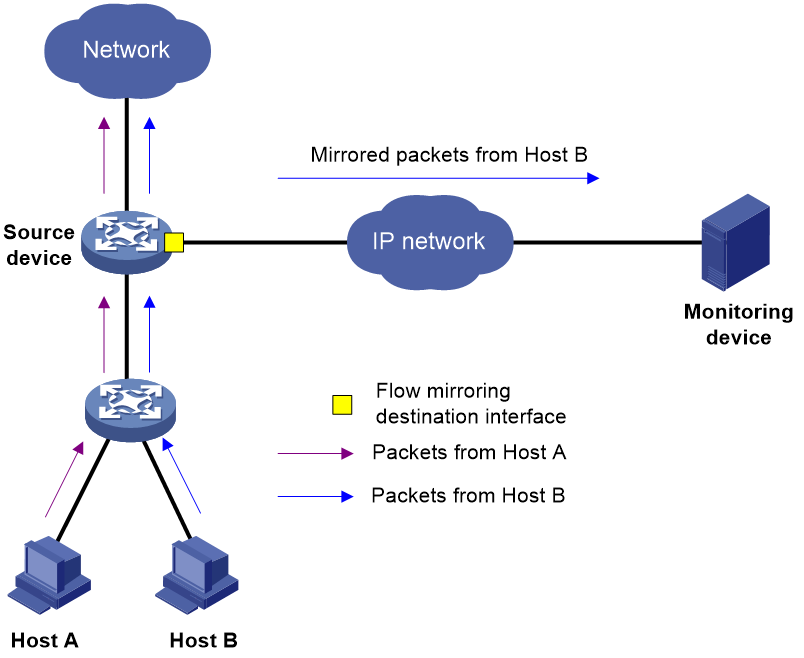
Encapsulation parameter mode
In this mode, configure a QoS policy on the source device. Configure the QoS policy as follows:
1. Configure a traffic class to match packets.
2. Configure a traffic behavior to flow-mirror traffic to an interface.
3. Associate the traffic class with the traffic behavior.
You can configure flow-mirroring traffic to an interface in one of the following modes:
· Directly specifying an outgoing interface—In this mode, specify both the outgoing interface and encapsulation parameters. The device encapsulates packets with the specified parameters and then forwards packets out of the specified interface.
· Specifying an outgoing interface through route lookup—In this mode, specify only encapsulation parameters without specifying an outgoing interface. The device looks up a route for the encapsulated mirrored packets based on the source IP address and destination IP address of the encapsulated packets. The outgoing interface of the route is a destination interface of the mirrored packets.
In this mode, you can use the load sharing function of a routing protocol to forward mirrored packets to multiple destination interfaces.
As shown in Figure 13, flow mirroring ERSPAN in encapsulation parameter mode works as follows:
1. The source device copies a matching packet.
2. The source device encapsulates the packet with the specified ERSPAN encapsulation parameters.
3. The source device forwards the packet in either of the following methods:
¡ Forwards the mirrored packets out of the specified outgoing interface.
¡ Looks up a route for the encapsulated mirrored packet based on the source IP address and destination IP address of the encapsulated packet.
4. The encapsulated packet is routed to the monitoring device.
5. The monitoring device decapsulates the packet and analyzes the packet contents.
The packet sent to the monitoring device through flow mirroring in this mode is encapsulated. In this mode, make sure the monitoring device supports decapsulating packets.
Figure 13 Flow mirroring ERSPAN in encapsulation parameter mode
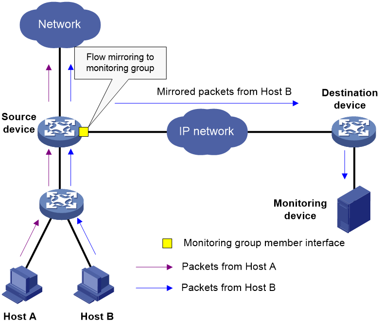
Monitoring group mode
As shown in Figure 14, flow mirroring ERSPAN in monitoring group mode works as follows:
1. On the source device, configure a monitoring group, add member interfaces to the monitoring group, and configure the encapsulation parameters for the member interfaces.
2. On the source device, apply a QoS policy as follows:
a. Configure a traffic class to match packets.
b. Configure a traffic behavior to mirror traffic to the monitoring group.
c. Create a QoS policy, and associate the traffic class with the traffic behavior in the QoS policy.
d. Apply the QoS policy.
3. The source device copies a matching packet and mirrors the packet to the monitoring group. The member interfaces of the monitoring group encapsulate the packet with the specified encapsulation parameters.
4. The source device forwards the packet in either of the following methods:
¡ Forwards the mirrored packet out of the specified outgoing interface.
¡ Looks up a route for the encapsulated mirrored packet based on the source IP address and destination IP address of the encapsulated packet.
5. The encapsulated packet is routed to the monitoring device.
6. The monitoring device decapsulates the packet and analyzes the packet contents.
The packet sent to the monitoring device through flow mirroring in this mode is encapsulated. In this mode, make sure the monitoring device supports decapsulating packets.
Figure 14 Flow mirroring ERSPAN in monitoring group mode
Restrictions and guidelines: Flow mirroring configuration
For information about the configuration commands except the mirror-to command, see ACL and QoS Command Reference.
On an IRF fabric, broadcast or unknown unicast packets cannot be mirrored when the following conditions exist:
· The mirroring destination is one monitor port or a monitoring group containing only one member port.
· The mirroring sources and the mirroring destination are not on the same IRF member device.
Flow mirroring tasks at a glance
To configure flow mirroring, perform the following tasks:
1. Configuring a traffic class
A traffic class defines the criteria that filters the traffic to be mirrored.
2. Configuring a traffic behavior
A traffic behavior specifies mirroring destinations.
Choose one of the following tasks:
¡ Applying a QoS policy to an interface
¡ Applying a QoS policy to a VLAN
¡ Applying a QoS policy globally
¡ Applying a QoS policy to the control plane
Configuring a traffic class
1. Enter system view.
system-view
2. Create a class and enter class view.
traffic classifier classifier-name [ operator { and | or } ]
3. Configure match criteria.
if-match match-criteria
By default, no match criterion is configured in a traffic class.
4. (Optional.) Display traffic class information.
display traffic classifier
This command is available in any view.
Configuring a traffic behavior
Procedure
1. Enter system view.
system-view
2. Configure a monitoring group.
a. Create a monitoring group.
monitoring-group group-id [ sampler sampler-name ]
b. Assign ports to the monitoring group.
Syntax 1:
monitoring-port interface-list [ destination-ip destination-ip-address source-ip source-ip-address [ dscp dscp-value | vlan vlan-id | vrf-instance vrf-name ] * [ destination-mac mac-address ] ]
Syntax 2:
monitoring-port destination-ip destination-ip-address source-ip source-ip-address [ dscp dscp-value | vlan vlan-id | vrf-instance vrf-name ] * [ destination-mac mac-address ]
By default, a monitoring group does not contain any port.
c. (Optional.) Enable mirrored packet truncation for the monitoring group.
truncation enable
By default, mirrored packet truncation is disabled for a monitoring group.
d. Return to system view.
quit
3. Create a traffic behavior and enter traffic behavior view.
traffic behavior behavior-name
4. Configure mirroring destinations for the traffic behavior. Choose one option as needed:
¡ Mirror traffic to interfaces.
mirror-to interface interface-type interface-number
By default, no mirroring actions exist to mirror traffic to interfaces.
¡ Mirror traffic to a monitoring group.
mirror-to monitoring-group group-id
By default, no mirroring actions exist to mirror traffic to a monitoring group.
¡ Mirror traffic to the CPU.
mirror-to cpu
By default, no mirroring actions exist to mirror traffic to the CPU.
5. (Optional.) Display traffic behavior configuration.
display traffic behavior
This command is available in any view.
Configuring a QoS policy
1. Enter system view.
system-view
2. Create a QoS policy and enter QoS policy view.
qos policy policy-name
3. Associate a class with a traffic behavior in the QoS policy.
classifier classifier-name behavior behavior-name
By default, no traffic behavior is associated with a class.
4. (Optional.) Display QoS policy configuration.
display qos policy
This command is available in any view.
Applying a QoS policy
Applying a QoS policy to an interface
Restrictions and guidelines
You can apply a QoS policy to an interface to mirror the traffic of the interface.
A policy can be applied to multiple interfaces.
In one traffic direction of an interface, only one QoS policy can be applied.
To apply a QoS policy to the outbound traffic of an interface, make sure mirroring actions do not coexist with non-mirroring actions in the same traffic behavior to avoid conflicts.
The device does not support mirroring outbound traffic of an aggregate interface.
Procedure
1. Enter system view.
system-view
2. Enter interface view.
interface interface-type interface-number
3. Apply a policy to the interface.
qos apply policy policy-name { inbound | outbound }
4. (Optional.) Display the QoS policy applied to the interface.
display qos policy interface
This command is available in any view.
Applying a QoS policy to a VLAN
Restrictions and guidelines
You can apply a QoS policy to a VLAN to mirror the traffic on all ports in the VLAN.
Procedure
1. Enter system view.
system-view
2. Apply a QoS policy to a VLAN.
qos vlan-policy policy-name vlan vlan-id-list { inbound | outbound }
3. (Optional.) Display the QoS policy applied to the VLAN.
display qos vlan-policy
This command is available in any view.
Applying a QoS policy globally
Restrictions and guidelines
You can apply a QoS policy globally to mirror the traffic on all ports.
Procedure
1. Enter system view.
system-view
2. Apply a QoS policy globally.
qos apply policy policy-name global { inbound | outbound }
3. (Optional.) Display global QoS policies.
display qos policy global
This command is available in any view.
Applying a QoS policy to the control plane
Restrictions and guidelines
You can apply a QoS policy to the control plane to mirror the traffic of all ports on the control plane.
Procedure
1. Enter system view.
system-view
2. Enter control plane view.
In standalone mode:
control-plane slot slot-number
In IRF mode:
control-plane chassis chassis-number slot slot-number
3. Apply a QoS policy to the control plane.
qos apply policy policy-name inbound
4. (Optional.) Display QoS policies applied to the control plane
display qos policy control-plane
This command is available in any view.
Display and maintenance commands for flow mirroring
Execute display commands in any view.
|
Task |
Command |
|
Display monitoring group information. |
display monitoring-group { group-id | all } |
Flow mirroring configuration examples
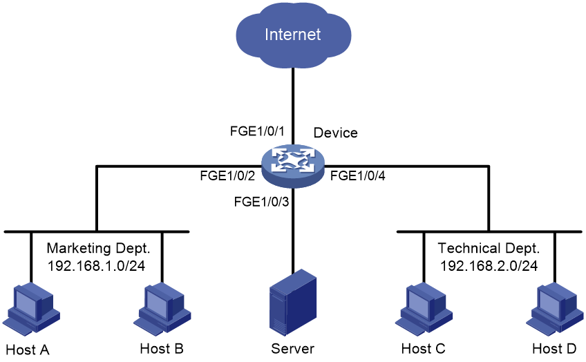
Example: Configuring flow mirroring
Network configuration
As shown in Figure 15, configure flow mirroring so that the server can monitor the following traffic:
· All traffic that the Technical Department sends to access the Internet.
· IP traffic that the Technical Department sends to the Marketing Department during working hours (8:00 to 18:00) on weekdays.
Procedure
|
|
IMPORTANT: By default, interfaces on the device are disabled (in ADM or Administratively Down state). To have an interface operate, you must use the undo shutdown command to enable that interface. |
# Create working hour range work, in which working hours are from 8:00 to 18:00 on weekdays.
<Device> system-view
[Device] time-range work 8:00 to 18:00 working-day
# Create IPv4 advanced ACL 3000 to allow packets from the Technical Department to access the Internet and the Marketing Department during working hours.
[Device] acl advanced 3000
[Device-acl-ipv4-adv-3000] rule permit tcp source 192.168.2.0 0.0.0.255 destination-port eq www
[Device-acl-ipv4-adv-3000] rule permit ip source 192.168.2.0 0.0.0.255 destination 192.168.1.0 0.0.0.255 time-range work
[Device-acl-ipv4-adv-3000] quit
# Create traffic class tech_c, and configure the match criterion as ACL 3000.
[Device] traffic classifier tech_c
[Device-classifier-tech_c] if-match acl 3000
[Device-classifier-tech_c] quit
# Create traffic behavior tech_b, configure the action of mirroring traffic to FortyGigE 1/0/3.
[Device] traffic behavior tech_b
[Device-behavior-tech_b] mirror-to interface fortygige 1/0/3
[Device-behavior-tech_b] quit
# Create QoS policy tech_p, and associate traffic class tech_c with traffic behavior tech_b in the QoS policy.
[Device] qos policy tech_p
[Device-qospolicy-tech_p] classifier tech_c behavior tech_b
[Device-qospolicy-tech_p] quit
# Apply QoS policy tech_p to the incoming packets of FortyGigE 1/0/4.
[Device] interface fortygige 1/0/4
[Device-FortyGigE1/0/4] qos apply policy tech_p inbound
[Device-FortyGigE1/0/4] quit
Verifying the configuration
# Verify that the server can monitor the following traffic:
· All traffic sent by the Technical Department to access the Internet.
· IP traffic that the Technical Department sends to the Marketing Department during working hours on weekdays.
(Details not shown.)
