- Table of Contents
- Related Documents
-
| Title | Size | Download |
|---|---|---|
| 02-Ethernet interface configuration | 247.30 KB |
Contents
Configuring Ethernet interfaces
Configuring a management Ethernet interface
Ethernet interface naming conventions
Configuring common Ethernet interface settings
Configuring the physical type for a combo interface (single combo interface)
Configuring basic settings of an Ethernet interface
Configuring basic settings of an Ethernet subinterface
Configuring the link mode of an Ethernet interface
Configuring jumbo frame support
Configuring physical state change suppression on an Ethernet interface
Configuring dampening on an Ethernet interface
Configuring generic flow control on an Ethernet interface
Configuring PFC on an Ethernet interface
Setting the statistics polling interval
Enabling subinterface rate statistics collection on an Ethernet interface
Enabling loopback testing on an Ethernet interface
Configuring interface alarm functions
Restoring the default settings for an interface
Configuring a Layer 2 Ethernet interface
Setting speed options for autonegotiation on an Ethernet interface
Setting the MDIX mode of an Ethernet interface
Configuring storm control on an Ethernet interface
Forcibly bringing up a fiber port
Testing the cable connection of an Ethernet interface
Configuring a Layer 3 Ethernet interface or subinterface
Setting the MTU for an Ethernet interface or subinterface
Setting the MAC address of an Ethernet interface or subinterface
Enabling destination MAC filtering
Display and maintenance commands
Configuring Ethernet interfaces
About Ethernet interface
This series devices support Ethernet interfaces, management Ethernet interfaces, Console interfaces, and USB interfaces. For the interface types and the number of interfaces supported by a device model, see the installation guide.
This chapter describes how to configure management Ethernet interfaces and Ethernet interfaces.
Configuring a management Ethernet interface
About this task
A management interface uses an RJ-45 connector. You can connect the interface to a PC for software loading and system debugging, or connect it to a remote NMS for remote system management.
(In standalone mode.)
Each MPU on a device has a management Ethernet interface. For management link backup, perform the following tasks:
1. Connect your PC to the management Ethernet interface on the active MPU.
2. Connect the PC to a management Ethernet interface with the same interface number on a standby MPU.
The two management Ethernet interfaces operate as follows:
· When the device has multiple management Ethernet interfaces, only the management Ethernet interface on the active MPU processes management traffic.
· When the management Ethernet interface on the active MPU fails, the management Ethernet interface on the standby MPU takes over to process management traffic.
· When the management Ethernet interface on the active MPU recovers, it takes over to process management traffic again.
(In IRF mode.)
Each MPU in an IRF system has a management Ethernet interface. For management link backup, perform the following tasks:
1. Connect your PC to the management Ethernet interface on the global active MPU.
2. Connect the PC to a management Ethernet interface with the same interface number on a global standby MPU.
The two management Ethernet interfaces operate as follows:
· When the IRF system has multiple management Ethernet interfaces, only the management Ethernet interface on the global active MPU processes management traffic.
· When the management Ethernet interface on the global active MPU fails, the management Ethernet interface on the global standby MPU takes over to process management traffic.
· When the management Ethernet interface on the global active MPU recovers, it takes over to process management traffic again.
Procedure
1. Enter system view.
system-view
2. Enter management Ethernet interface view.
interface M-GigabitEthernet interface-number
3. (Optional.) Set the interface description.
description text
The default setting is M-GigabitEthernet0/0/0 Interface.
4. (Optional.) Set the duplex mode for the management Ethernet interface.
duplex { auto | full | half }
By default, the duplex mode is auto for a management Ethernet interface.
Support for the full and half keywords of the command depends on the device model. For information, see Interface Command Reference.
5. (Optional.)_Set the speed for the management Ethernet interface.
speed { 10 | 100 | 1000 | auto }
By default, the speed is auto for a management Ethernet interface.
6. (Optional.) Shut down the interface.
shutdown
By default, the management Ethernet interface is up.
|
|
CAUTION: Executing the shutdown command on an interface will disconnect the link of the interface and interrupt communication. Use this command with caution. |
Ethernet interface naming conventions
In standalone mode:
The Ethernet interfaces are named in the format of interface type A/0/B. The letters that follow the interface type represent the following elements:
· A—Card slot number. 0 indicates the interface is a fixed interface of the device. 1 indicates the interface is on expansion interface card 1. 2 indicates the interface is on expansion interface card 2.
· B—Port index.
In IRF mode:
The Ethernet interfaces are named in the format of interface type A/B/0/C. The letters that follow the interface type represent the following elements:
· A—IRF member ID. If the device is not in an IRF fabric, A is 1 by default.
· B—Card slot number. 0 indicates the interface is a fixed interface of the device. 1 indicates the interface is on expansion interface-card 1. 2 indicates the interface is on expansion interface-card 2.
· C—Port index.
Configuring common Ethernet interface settings
This section describes the settings common to Layer 2 Ethernet interfaces, Layer 3 Ethernet interfaces, and Layer 3 Ethernet subinterfaces. For more information about the settings specific to Layer 2 Ethernet interfaces, see "Configuring a Layer 2 Ethernet interface." For more information about the settings specific to Layer 3 Ethernet interfaces or subinterfaces, see "Configuring a Layer 3 Ethernet interface or subinterface."
Configuring the physical type for a combo interface (single combo interface)
About this task
A combo interface is a logical interface that physically comprises one fiber combo port and one copper combo port. The two ports share one forwarding channel and one interface view. As a result, they cannot work simultaneously. When you activate one port, the other port is automatically disabled. In the interface view, you can activate the fiber or copper combo port, and configure other port attributes such as the interface rate and duplex mode.
Prerequisites
Before you configure combo interfaces, complete the following tasks:
· Determine the combo interfaces on your device. Identify the two physical interfaces that belong to each combo interface according to the marks on the device panel.
· Use the display interface command to determine which port (fiber or copper) of each combo interface is active:
¡ If the copper port is active, the output includes "Media type is twisted pair, Port hardware type is 1000_BASE_T."
¡ If the fiber port is active, the output does not include this information.
Also, you can use the display this command in the view of each combo interface to display the combo interface configuration:
¡ If the fiber port is active, the combo enable fiber command exists in the output.
¡ If the copper port is active, the combo enable fiber command does not exist in the output.
Procedure
1. Enter system view.
system-view
2. Enter Ethernet interface view.
interface interface-type interface-number
3. Activate the copper combo port or fiber combo port.
combo enable { copper | fiber }
By default, the copper combo port is active.
Configuring basic settings of an Ethernet interface
About this task
You can configure an Ethernet interface to operate in one of the following duplex modes:
· Full-duplex mode—The interface can send and receive packets simultaneously.
· Half-duplex mode—The interface can only send or receive packets at a given time.
· Autonegotiation mode—The interface negotiates a duplex mode with its peer.
You can set the speed of an Ethernet interface or enable it to automatically negotiate a speed with its peer.
Restrictions and guidelines
The shutdown, port up-mode, and loopback commands are mutually exclusive.
Procedure
1. Enter system view.
system-view
2. Enter Ethernet interface view.
interface interface-type interface-number
3. Set the description for the Ethernet interface.
description text
The default setting is interface-name Interface. For example, GigabitEthernet1/0/1 Interface.
4. Set the duplex mode for the Ethernet interface.
duplex { auto | full | half }
By default, the duplex mode is auto for Ethernet interfaces.
Fiber ports do not support the half keyword.
5. Set the speed for the Ethernet interface.
speed { 10 | 100 | 1000 | 10000 | 40000 | 100000 | auto }
By default, an interface autonegotiates its speed.
6. Set the expected bandwidth for the Ethernet interface.
bandwidth bandwidth-value
By default, the expected bandwidth (in kbps) is the interface baud rate divided by 1000.
7. Bring up the Ethernet interface.
undo shutdown
By default, an Ethernet interface is up.
Configuring basic settings of an Ethernet subinterface
Restrictions and guidelines for Ethernet subinterface basic settings
· To transmit and receive packets through an Ethernet subinterface, you must associate it with a VLAN. For more information, see VLAN termination configuration in Layer 2—LAN Switching Configuration Guide.
· To transmit packets between a local Ethernet subinterface and a remote Ethernet subinterface, configure them with the same subinterface number and VLAN ID.
· Before creating a Layer 3 Ethernet subinterface, do not reserve a resource for the VLAN interface whose interface number is the subinterface number. After you reserve a VLAN interface resource, do not create a Layer 3 Ethernet subinterface whose subinterface number is the VLAN interface number. A Layer 3 Ethernet subinterface uses the VLAN interface resource in processing tagged packets whose VLAN ID matches the subinterface number. For more information about reserving resources for VLAN interfaces, see Layer 2—LAN Switching Configuration Guide.
· The shutdown, port up-mode, and loopback commands are mutually exclusive.
· The shutdown command cannot be configured on an Ethernet interface in a loopback test.
Procedure
1. Enter system view.
system-view
2. Create an Ethernet subinterface.
interface interface-type interface-number.subnumber
3. Set the description for the Ethernet subinterface.
description text
The default setting is interface-name Interface. For example, GigabitEthernet1/0/1.1 Interface.
4. Set the expected bandwidth for the Ethernet subinterface.
bandwidth bandwidth-value
By default, the expected bandwidth (in kbps) is the interface baud rate divided by 1000.
5. Bring up the Ethernet subinterface.
undo shutdown
By default, an Ethernet interface is up.
Configuring the link mode of an Ethernet interface
About this task
Ethernet interfaces operate differently depending on the hardware structure of interface cards:
· Some Ethernet interfaces can operate only as Layer 2 Ethernet interfaces (in bridge mode).
· Some Ethernet interfaces can operate only as Layer 3 Ethernet interfaces (in route mode).
· Some Ethernet interfaces can operate either as Layer 2 or Layer 3 Ethernet interfaces. You can set the link mode to bridge or route for these Ethernet interfaces.
Restrictions and guidelines
After you change the link mode of an Ethernet interface, all commands (except the shutdown and combo enable commands) on the Ethernet interface are restored to their defaults in the new link mode.
Procedure
1. Enter system view.
system-view
2. Enter Ethernet interface view.
interface interface-type interface-number
3. Configure the link mode of the Ethernet interface.
port link-mode { bridge | route }
By default, an Ethernet interface operates in Layer 3 mode.
|
|
CAUTION: After you change the link mode of an Ethernet interface, all commands (except the shutdown and combo enable commands) on the Ethernet interface are restored to their defaults in the new link mode. |
Configuring jumbo frame support
About this task
Jumbo frames are frames larger than a device-specific size and are typically received by an Ethernet interface during high-throughput data exchanges, such as file transfers.
The Ethernet interface processes jumbo frames in the following ways:
· When the Ethernet interface is configured to deny jumbo frames (by using the undo jumboframe enable command), the Ethernet interface discards jumbo frames.
· When the Ethernet interface is configured with jumbo frame support, the Ethernet interface performs the following operations:
¡ Processes jumbo frames within the specified length.
¡ Discards jumbo frames that exceed the specified length.
Procedure
1. Enter system view.
system-view
2. Enter Ethernet interface view.
interface interface-type interface-number
3. Configure jumbo frame support.
jumboframe enable [ size ]
By default, the device allows jumbo frames within 9216 bytes to pass through.
If you set the size argument multiple times, the most recent configuration takes effect.
Configuring physical state change suppression on an Ethernet interface
About this task
The physical link state of an Ethernet interface is either up or down. Each time the physical link of an interface comes up or goes down, the interface immediately reports the change to the CPU. The CPU then performs the following operations:
· Notifies the upper-layer protocol modules (such as routing and forwarding modules) of the change for guiding packet forwarding.
· Automatically generates traps and logs to inform users to take the correct actions.
To prevent frequent physical link flapping from affecting system performance, configure physical state change suppression. You can configure this feature to suppress only link-down events, only link-up events, or both. If an event of the specified type still exists when the suppression interval expires, the system reports the event to the CPU.
Restrictions and guidelines
Do not enable this feature on an interface that has spanning tree protocols enabled.
You can configure different suppression intervals for link-up and link-down events.
If you configure this command multiple times for link-up or link-down events on an Ethernet interface, the most recent configuration takes effect.
The link-delay and dampening commands are mutually exclusive on an Ethernet interface.
On an interface, you can configure different suppression intervals for link-up and link-down events. If you configure the link-delay command multiple times for link-up or link-down events, the most recent configuration takes effect.
Procedure
1. Enter system view.
system-view
2. Enter Ethernet interface view.
interface interface-type interface-number
3. Configure physical state change suppression.
link-delay [ msec ] delay-time [ mode { up | updown }]
By default, physical state change suppression is disabled.
To suppress only link-down events, do not specify the mode keyword. To suppress only link-up events, specify the mode up keywords. To suppress both link-down and link-up events, specify the mode updown keywords.
Configuring dampening on an Ethernet interface
About this task
The interface dampening feature uses an exponential decay mechanism to prevent excessive interface flapping events from adversely affecting routing protocols and routing tables in the network. Suppressing interface state change events protects the system resources.
If an interface is not dampened, its state changes are reported. For each state change, the system also generates an SNMP trap and log message.
After a flapping interface is dampened, it does not report its state changes to the CPU. For state change events, the interface only generates SNMP trap and log messages.
Parameters
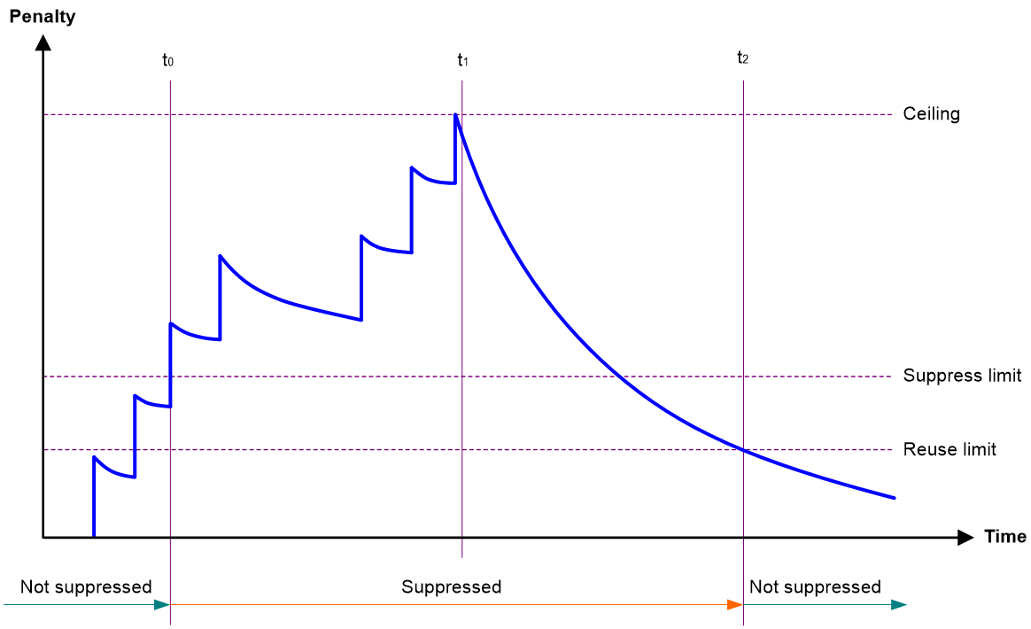
· Penalty—The interface has an initial penalty of 0. When the interface flaps, the penalty increases by 1000 for each down event until the ceiling is reached. It does not increase for up events. When the interface stops flapping, the penalty decreases by half each time the half-life timer expires until the penalty drops to the reuse threshold.
· Ceiling—The penalty stops increasing when it reaches the ceiling.
· Suppress-limit—The accumulated penalty that triggers the device to dampen the interface. In dampened state, the interface does not report its state changes to the CPU. For state change events, the interface only generates SNMP traps and log messages.
· Reuse-limit—When the accumulated penalty decreases to this reuse threshold, the interface is not dampened. Interface state changes are reported to the upper layers. For each state change, the system also generates an SNMP trap and log message.
· Decay—The amount of time (in seconds) after which a penalty is decreased.
· Max-suppress-time—The maximum amount of time the interface can be dampened. If the penalty is still higher than the reuse threshold when this timer expires, the penalty stops increasing for down events. The penalty starts to decrease until it drops below the reuse threshold.
When configuring the dampening command, follow these rules to set the values mentioned above:
· The ceiling is equal to 2(Max-suppress-time/Decay) × reuse-limit. It is not user configurable.
· The configured suppress limit is lower than or equal to the ceiling.
· The ceiling is lower than or equal to the maximum suppress limit supported.
Figure 1 shows the change rule of the penalty value. The lines t0 and t2 indicate the start time and end time of the suppression, respectively. The period from t0 to t2 indicates the suppression period, t0 to t1 indicates the max-suppress-time, and t1 to t2 indicates the complete decay period.
Figure 1 Change rule of the penalty value
Restrictions and guidelines
· The dampening and link-delay commands are mutually exclusive on an interface.
· The dampening command does not take effect on the administratively down events. When you execute the shutdown command, the penalty restores to 0, and the interface reports the down event to the upper-layer protocols.
· Do not enable this feature on an interface that has spanning tree protocols enabled.
Procedure
1. Enter system view.
system-view
2. Enter Ethernet interface view.
interface interface-type interface-number
3. Enable dampening on the interface.
dampening [ half-life reuse suppress max-suppress-time ]
By default, interface dampening is disabled on Ethernet interfaces.
Configuring FEC
About this task
The forward error correction (FEC) feature corrects packet errors to improve transmission quality. It attaches correction information to a packet at the sending end, and corrects error codes generated during transmission at the receiving end based on the correction information. You can set the FEC mode as needed.
Restrictions and guidelines
This feature is supported only on 100-GE interfaces.
Make sure you set the same FEC mode for both interfaces of a link.
Procedure
1. Enter system view.
system-view
2. Enter Ethernet interface view.
interface interface-type interface-number
3. Set the FEC mode of the Ethernet interface.
port fec mode { auto | none | rs-fec }
By default, the FEC mode of an interface is autonegotiated.
Configuring storm suppression
About this task
The storm suppression feature ensures that the size of a particular type of traffic (broadcast or multicast traffic) does not exceed the threshold on an interface. When the broadcast or multicast traffic on the interface exceeds this threshold, the system discards packets until the traffic drops below this threshold.
Both storm suppression and storm control can suppress storms on an interface. Storm suppression uses the chip to suppress traffic. Storm suppression has less impact on the device performance than storm control, which uses software to suppress traffic.
Hardware and feature compatibility
Hardware and feature compatibility
This feature is not supported on the NSQ1GP24TXEA0, NSQ1GP48EB0, NSQ1GT48EA0, or NSQ1TGX4EA0 interface cards.
Restrictions and guidelines
· For the traffic suppression result to be determined, do not configure storm control together with storm suppression for the same type of traffic. For more information about storm control, see "Configuring storm control on an Ethernet interface."
· The configured suppression threshold value in pps might be converted into a multiple of the step value supported by the chip. As a result, the effective suppression threshold might be different from the configured one. For information about the suppression threshold that takes effect, see the prompt on the device.
Procedure
system-view
2. Enter Ethernet interface view.
interface interface-type interface-number
3. Enable broadcast suppression and set the broadcast suppression threshold.
broadcast-suppression pps max-pps
By default, broadcast suppression is disabled.
4. Enable multicast suppression and set the multicast suppression threshold.
multicast-suppression pps max-pps
By default, multicast suppression is disabled.
Configuring generic flow control on an Ethernet interface
About this task
To avoid dropping packets on a link, you can enable generic flow control at both ends of the link. When traffic congestion occurs at the receiving end, the receiving end sends a flow control (Pause) frame to ask the sending end to suspend sending packets. Generic flow control includes the following types:
· TxRx-mode generic flow control—Enabled by using the flow-control command. With TxRx-mode generic flow control enabled, an interface can both send and receive flow control frames:
¡ When congestion occurs, the interface sends a flow control frame to its peer.
¡ When the interface receives a flow control frame from its peer, it suspends sending packets to its peer.
· Rx-mode generic flow control—Enabled by using the flow-control receive enable command. With Rx-mode generic flow control enabled, an interface can receive flow control frames, but it cannot send flow control frames:
¡ When congestion occurs, the interface cannot send flow control frames to its peer.
¡ When the interface receives a flow control frame from its peer, it suspends sending packets to its peer.
To handle unidirectional traffic congestion on a link, configure the flow-control receive enable command at one end and the flow-control command at the other end. To enable both ends of a link to handle traffic congestion, configure the flow-control command at both ends.
Procedure
1. Enter system view.
system-view
2. Enter Ethernet interface view.
interface interface-type interface-number
3. Enable generic flow control. Choose one of the following tasks:
¡ Enable TxRx-mode generic flow control.
flow-control
¡ Enable Rx-mode generic flow control.
flow-control receive enable
By default, generic flow control is disabled on an Ethernet interface.
Configuring PFC on an Ethernet interface
About this task
When congestion occurs in the network, the local device notifies the peer to stop sending packets carrying the specified 802.1p priority if all of the following conditions exist:
· Both the local end and the remote end have priority-based flow control (PFC) enabled.
· Both the local end and the remote end have the priority-flow-control no-drop dot1p command configured.
· The specified 802.1p priority is in the 802.1p priority list specified by the dot1p-list argument.
· The local end receives a packet carrying the specified 802.1p priority.
The state of the PFC feature is determined by the PFC configuration on the local end and on the peer end. In Table 1:
· The first row lists the PFC configuration on the local interface.
· The first column lists the PFC configuration on the peer.
· The Enabled and Disabled fields in other cells are possible negotiation results.
Make sure all interfaces that a data flow passes through have the same PFC configuration.
Table 1 PFC configurations and negotiation results
|
Local (right) Peer (below) |
enable |
auto |
Default |
|
enable |
Enabled |
Enabled. |
Disabled |
|
auto |
Enabled |
· Enabled if negotiation succeeds. · Disabled if negotiation fails. |
Disabled |
|
Default |
Disabled |
Disabled. |
Disabled |
Restrictions and guidelines
· For IRF and other protocols to operate correctly, as a best practice, do not enable PFC for 802.1p priorities 0, 6, and 7.
· To perform PFC on an Ethernet interface, make sure the following conditions are met:
¡ PFC is configured in both system view and Ethernet interface view.
¡ The 802.1p priority list specified in Ethernet interface view is a sublist of the 802.1p priority list specified in system view.
· To perform PFC on an IRF port, configure PFC on the IRF port and the IRF physical ports that are bound to the IRF port. For information about IRF, see IRF configuration Guide.
· To perform PFC in an overlay network, execute the qos trust tunnel-dot1p command. For information about the overlay network, see VXLAN Configuration Guide. For information about the qos trust tunnel-dot1p command, see ACL and QoS Command Reference.
· To avoid packet loss, apply the same PFC configuration to all interfaces that the packets pass through.
· If you do not enable PFC on an interface, the interface can receive but cannot process PFC pause frames. To make PFC take effect, you must enable PFC on both ends.
· If you configure the flow control or flow-control receive enable command on a PFC-enabled interface, the following rules apply:
¡ The PFC configuration takes effect.
¡ The configuration of the flow control or flow-control receive enable command is ignored.
¡ The flow control or flow-control receive enable command takes effect on the interface only when PFC is disabled on it.
Procedure
1. Enter system view.
system-view
2. Enable PFC in auto mode or forcibly.
priority-flow-control { auto | enable }
By default, PFC is disabled.
3. Enable PFC for 802.1p priorities.
priority-flow-control no-drop dot1p dot1p-list
By default, PFC is disabled for all 802.1p priorities.
Setting the statistics polling interval
About this task
To display the interface statistics collected in the last statistics polling interval, use the display interface command. To clear the interface statistics, use the reset counters interface command.
A device supports either the system view settings or the Ethernet interface view settings.
· The statistics polling interval configured in system view takes effect on all Ethernet interface.
· The statistics polling interval configured in Ethernet interface view takes effect only on the current interface.
The statistics polling interval configured in Ethernet interface view takes precedence over the statistics polling interval configured in system view. The interval configured in system view takes effect on an Ethernet interface only when no interval is configured or the default interval is configured for the Ethernet interface.
Restrictions and guidelines for setting the statistics polling interval
· As a best practice, use the default setting when you set the statistics polling interval in system view. A short statistics polling interval might decrease the system performance and result in inaccurate statistics.
Setting the statistics polling interval in system view
1. Enter system view.
system-view
2. Set the statistics polling interval.
flow-interval interval
By default, the statistics polling interval is 300 seconds.
Setting the statistics polling interval in Ethernet interface view
1. Enter system view.
system-view
2. Enter Ethernet interface view.
interface interface-type interface-number
3. Set the statistics polling interval for the Ethernet interface.
flow-interval interval
By default, the statistics polling interval is 300 seconds.
Enabling subinterface rate statistics collection on an Ethernet interface
Restrictions and guidelines
This feature is resource intensive. When you use this feature, make sure you fully understand its impact on system performance.
After you enable subinterface rate statistics collection on an Ethernet interface, the device periodically refreshes the rate statistics on the subinterfaces of this Ethernet interface.
Procedure
1. Enter system view.
system-view
2. Enter Ethernet interface view.
interface interface-type interface-number
3. Enable subinterface rate statistics collection on the Ethernet interface.
sub-interface rate-statistic
By default, subinterface rate statistics collection is disabled on an Ethernet interface.
4. (Optional.) View the subinterface rate statistics.
display interface
Enabling loopback testing on an Ethernet interface
About this task
Perform this task to determine whether an Ethernet link works correctly.
Loopback testing includes the following types:
· Internal loopback testing—Tests the device where the Ethernet interface resides. The Ethernet interface sends outgoing packets back to the local device. If the device fails to receive the packets, the device fails.
· External loopback testing—Tests the inter-device link. The Ethernet interface sends incoming packets back to the remote device. If the remote device fails to receive the packets, the inter-device link fails.
Restrictions and guidelines
· After you enable this feature on an Ethernet interface, the interface does not forward data traffic.
· The shutdown, port up-mode, and loopback commands are mutually exclusive.
· After you enable this feature on an Ethernet interface, the Ethernet interface switches to full duplex mode. After you disable this feature, the Ethernet interface restores to its duplex setting.
Procedure
1. Enter system view.
system-view
2. Enter Ethernet interface view.
interface interface-type interface-number
3. Enable loopback testing.
loopback { external | internal }
Configuring interface alarm functions
About this task
With the interface alarm functions enabled, when the number of sent or received error packets or the input or output bandwidth usage on an interface in normal state within the specified interval exceeds the upper threshold, the interface generates an upper threshold exceeding alarm and enters the alarm state. When the number of sent or received error packets or the input or output bandwidth usage on an interface in the alarm state within the specified interval drops below the lower threshold, the interface generates a recovery alarm and restores to the normal state.
Restrictions and guidelines
You can configure the error packet alarm parameters in system view and interface view.
· The configuration in system view takes effect on all interfaces of the specified slot. The configuration in interface view takes effect only on the current interface.
· For an interface, the configuration in interface view takes priority, and the configuration in system view is used only when no configuration is made in interface view.
An interface that is shut down because of error packet alarms cannot automatically recover. To bring up the interface, execute the undo shutdown command on the interface.
Enabling interface alarm functions
1. Enter system view.
system-view
2. Enable alarm functions for the interface monitoring module.
snmp-agent trap enable ifmonitor [ crc-error | input-error | input-usage | output-error | output-usage | rx-pause | sdh-b1-error | sdh-b2-error | sdh-error | tx-pause ] *
By default, all alarm functions are enabled for interfaces.
Configuring CRC error packet alarm parameters
1. Enter system view.
system-view
2. Configure global CRC error packet alarm parameters.
In standalone mode:
ifmonitor crc-error slot slot-number cpu cpu-number high-threshold high-value low-threshold low-value interval interval [ shutdown ]
In IRF mode:
ifmonitor crc-error chassis chassis-number slot slot-number cpu cpu-number high-threshold high-value low-threshold low-value interval interval [ shutdown ]
By default, the upper threshold is 1000, the lower threshold is 100, and the statistics collection and comparison interval is 10 seconds for CRC error packets.
3. Enter Ethernet interface view.
interface interface-type interface-number
4. Configure CRC error packet alarm parameters for the interface.
port ifmonitor crc-error [ ratio ] high-threshold high-value low-threshold low-value interval interval [ shutdown ]
By default, an interface uses the global CRC error packet alarm parameters.
Configuring input error packet alarm parameters
1. Enter system view.
system-view
2. Configure global input error packet alarm parameters.
In standalone mode:
ifmonitor input-error slot slot-number cpu cpu-number high-threshold high-value low-threshold low-value interval interval [ shutdown ]
In IRF mode:
ifmonitor input-error chassis chassis-number slot slot-number cpu cpu-number high-threshold high-value low-threshold low-value interval interval [ shutdown ]
By default, the upper threshold is 1000, the lower threshold is 100, and the statistics collection and comparison interval is 10 seconds for input error packets.
3. Enter Ethernet interface view.
interface interface-type interface-number
4. Configure input error packet alarm parameters for the interface.
port ifmonitor input-error high-threshold high-value low-threshold low-value interval interval [ shutdown ]
By default, an interface uses the global input error packet alarm parameters.
Configuring output error packet alarm parameters
1. Enter system view.
system-view
2. Configure global output error packet alarm parameters.
In standalone mode:
ifmonitor output-error slot slot-number cpu cpu-number high-threshold high-value low-threshold low-value interval interval [ shutdown ]
In IRF mode:
ifmonitor output-error chassis chassis-number slot slot-number cpu cpu-number high-threshold high-value low-threshold low-value interval interval [ shutdown ]
By default, the upper threshold is 1000, the lower threshold is 100, and the statistics collection and comparison interval is 10 seconds for output error packets.
3. Enter Ethernet interface view.
interface interface-type interface-number
4. Configure output error packet alarm parameters.
port ifmonitor output-error high-threshold high-value low-threshold low-value interval interval [ shutdown ]
By default, an interface uses the global output error packet alarm parameters.
Configuring input bandwidth usage alarm parameters
1. Enter system view.
system-view
2. Configure global input bandwidth usage alarm parameters.
In standalone mode:
ifmonitor input-usage slot slot-number cpu cpu-number high-threshold high-value low-threshold low-value
In IRF mode:
ifmonitor input-usage chassis chassis-number slot slot-number cpu cpu-number high-threshold high-value low-threshold low-value
By default, the upper threshold is 90 and the lower threshold is 80 for input bandwidth usage alarms.
3. Enter Ethernet interface view.
interface interface-type interface-number
4. Configure input bandwidth usage alarm parameters.
port ifmonitor input-usage high-threshold high-value low-threshold low-value
By default, an interface uses the global input bandwidth usage alarm parameters.
Configuring output bandwidth usage alarm parameters
1. Enter system view.
system-view
2. Configure global output bandwidth usage alarm parameters.
In standalone mode:
ifmonitor output-usage slot slot-number cpu cpu-number high-threshold high-value low-threshold low-value
In IRF mode:
ifmonitor output-usage chassis chassis-number slot slot-number cpu cpu-number high-threshold high-value low-threshold low-value
By default, the upper threshold is 90 and the lower threshold is 80 for output bandwidth usage alarms.
3. Enter Ethernet interface view.
interface interface-type interface-number
4. Configure output bandwidth usage alarm parameters.
port ifmonitor output-usage high-threshold high-value low-threshold low-value
By default, an interface uses the global output bandwidth usage alarm parameters.
Configuring received pause frame alarm parameters
1. Enter system view.
system-view
2. Configure global received pause frame alarm parameters.
In standalone mode:
ifmonitor rx-pause slot slot-number cpu cpu-number high-threshold high-value low-threshold low-value interval interval
In IRF mode:
ifmonitor rx-pause chassis chassis-number slot slot-number cpu cpu-number high-threshold high-value low-threshold low-value interval interval
By default, the upper threshold is 500, the lower threshold is 100, and the statistics collection and comparison interval is 10 seconds for received pause frames.
3. Enter Ethernet interface view.
interface interface-type interface-number
4. Configure received pause frame alarm parameters.
port ifmonitor rx-pause high-threshold high-value low-threshold low-value interval interval
By default, an interface uses the global received pause frame alarm parameters.
Configuring sent pause frame alarm parameters
1. Enter system view.
system-view
2. Configure global sent pause frame alarm parameters.
In standalone mode:
ifmonitor tx-pause slot slot-number cpu cpu-number high-threshold high-value low-threshold low-value interval interval
In IRF mode:
ifmonitor tx-pause chassis chassis-number slot slot-number cpu cpu-number high-threshold high-value low-threshold low-value interval interval
By default, the upper threshold is 500, the lower threshold is 100, and the statistics collection and comparison interval is 10 seconds for sent pause frames.
3. Enter Ethernet interface view.
interface interface-type interface-number
4. Configure sent pause frame alarm parameters.
port ifmonitor tx-pause high-threshold high-value low-threshold low-value interval interval
By default, an interface uses the global sent pause frame alarm parameters.
Configuring SDH error packet alarm parameters
1. Enter system view.
system-view
2. Configure global SDH error packet alarm parameters.
In standalone mode:
ifmonitor sdh-error slot slot-number cpu cpu-number high-threshold high-value low-threshold low-value interval interval [ shutdown ]
In IRF mode:
ifmonitor sdh-error chassis chassis-number slot slot-number cpu cpu-number high-threshold high-value low-threshold low-value interval interval [ shutdown ]
By default, the upper threshold is 1000, the lower threshold is 100, and the statistics collection and comparison interval is 10 seconds for SDH error packets.
3. Enter Ethernet interface view.
interface interface-type interface-number
4. Configure SDH error packet alarm parameters for the interface.
port ifmonitor sdh-error high-threshold high-value low-threshold low-value interval interval [ shutdown ]
By default, an interface uses the global SDH error packet alarm parameters.
Configuring SDH-B1 error packet alarm parameters
1. Enter system view.
system-view
2. Configure global SDH-B1 error packet alarm parameters.
In standalone mode:
ifmonitor sdh-b1-error slot slot-number cpu cpu-number high-threshold high-value low-threshold low-value interval interval [ shutdown ]
In IRF mode:
ifmonitor sdh-b1-error chassis chassis-number slot slot-number cpu cpu-number high-threshold high-value low-threshold low-value interval interval [ shutdown ]
By default, the upper threshold is 1000, the lower threshold is 100, and the statistics collection and comparison interval is 10 seconds for SDH-B1 error packets.
3. Enter Ethernet interface view.
interface interface-type interface-number
4. Configure SDH-B1 error packet alarm parameters for the interface.
port ifmonitor sdh-b1-error high-threshold high-value low-threshold low-value interval interval [ shutdown ]
By default, an interface uses the global SDH-B1 error packet alarm parameters.
Configuring SDH-B2 error packet alarm parameters
1. Enter system view.
system-view
2. Configure global SDH-B2 error packet alarm parameters.
In standalone mode:
ifmonitor sdh-b2-error slot slot-number cpu cpu-number high-threshold high-value low-threshold low-value interval interval [ shutdown ]
In IRF mode:
ifmonitor sdh-b2-error chassis chassis-number slot slot-number cpu cpu-number high-threshold high-value low-threshold low-value interval interval [ shutdown ]
By default, the upper threshold is 1000, the lower threshold is 100, and the statistics collection and comparison interval is 10 seconds for SDH-B2 error packets.
3. Enter Ethernet interface view.
interface interface-type interface-number
4. Configure SDH-B2 error packet alarm parameters for the interface.
port ifmonitor sdh-b2-error high-threshold high-value low-threshold low-value interval interval [ shutdown ]
By default, an interface uses the global SDH-B2 error packet alarm parameters.
Restoring the default settings for an interface
Restrictions and guidelines
|
|
CAUTION: This feature might interrupt ongoing network services. Make sure you are fully aware of the impacts of this feature when you use it in a live network. |
This feature might fail to restore the default settings for some commands because of command dependencies or system restrictions. You can use the display this command in interface view to check for these commands and perform their undo forms or follow the command reference to restore their default settings. If your restoration attempt still fails, follow the error message to resolve the problem.
Procedure
1. Enter system view.
system-view
2. Enter Ethernet interface view or Ethernet subinterface view.
interface interface-type { interface-number | interface-number.subnumber }
3. Restore the default settings for the interface.
default
Configuring a Layer 2 Ethernet interface
Setting speed options for autonegotiation on an Ethernet interface
About this task
By default, speed autonegotiation enables an Ethernet interface to negotiate with its peer for the highest speed that both ends support. You can narrow down the speed option list for negotiation.
Figure 2 Speed autonegotiation application scenario
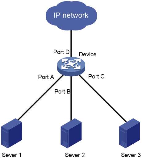
As shown in Figure 2:
· All interfaces on the device are operating in speed autonegotiation mode, with the highest speed of 1000 Mbps.
· Port D provides access to the Internet for the servers.
If the transmission rate of each server in the server cluster is 1000 Mbps, their total transmission rate exceeds the capability of Port D.
To avoid congestion on Port D, configure 100 Mbps as the only option available for speed negotiation on interfaces Port A, Port B, and Port C. As a result, the transmission rate on each interface connected to a server is limited to 100 Mbps.
Restrictions and guidelines
The speed and speed auto commands supersede each other, and whichever is configured last takes effect.
Procedure
1. Enter system view.
system-view
2. Enter Ethernet interface view.
interface interface-type interface-number
3. Set speed options for autonegotiation.
speed auto { 10 | 100 | 1000 } *
By default, no speed options are set for autonegotiation.
Setting the MDIX mode of an Ethernet interface
|
|
IMPORTANT: Fiber ports do not support the MDIX mode setting. |
About this task
A physical Ethernet interface has eight pins, each of which plays a dedicated role. For example, pins 1 and 2 transmit signals, and pins 3 and 6 receive signals. You can use both crossover and straight-through Ethernet cables to connect copper Ethernet interfaces. To accommodate these types of cables, a copper Ethernet interface can operate in one of the following Medium Dependent Interface-Crossover (MDIX) modes:
· MDIX mode—Pins 1 and 2 are receive pins and pins 3 and 6 are transmit pins.
· MDI mode—Pins 1 and 2 are transmit pins and pins 3 and 6 are receive pins.
· AutoMDIX mode—The interface negotiates pin roles with its peer.
|
|
NOTE: This feature does not take effect on pins 4, 5, 7, and 8 of physical Ethernet interfaces. · Pins 4, 5, 7, and 8 of interfaces operating at 10 Mbps or 100 Mbps do not receive or transmit signals. · Pins 4, 5, 7, and 8 of interfaces operating at 1000 Mbps or higher rates receive and transmit signals. |
Restrictions and guidelines
To enable a copper Ethernet interface to communicate with its peer, set the MDIX mode of the interface by following these guidelines:
· Typically, set the MDIX mode of the interface to AutoMDIX. Set the MDIX mode of the interface to MDI or MDIX only when the device cannot determine the cable type.
· When a straight-through cable is used, configure the interface to operate in an MDIX mode different than its peer.
· When a crossover cable is used, perform one of the following tasks:
¡ Configure the interface to operate in the same MDIX mode as its peer.
¡ Configure either end to operate in AutoMDIX mode.
Procedure
1. Enter system view.
system-view
2. Enter Ethernet interface view.
interface interface-type interface-number
3. Set the MDIX mode of the Ethernet interface.
mdix-mode { automdix | mdi | mdix }
By default, a copper Ethernet interface operates in auto mode to negotiate pin roles with its peer.
Configuring storm control on an Ethernet interface
About this task
Storm control compares broadcast, multicast, and unknown unicast traffic regularly with their respective traffic thresholds on an Ethernet interface. For each type of traffic, storm control provides a lower threshold and an upper threshold.
Depending on your configuration, when a particular type of traffic exceeds its upper threshold, the interface performs either of the following operations:
· Blocks this type of traffic and forwards other types of traffic—Even though the interface does not forward the blocked traffic, it still counts the traffic. When the blocked traffic drops below the lower threshold, the interface begins to forward the traffic.
· Goes down automatically—The interface goes down automatically and stops forwarding any traffic. When the blocked traffic drops below the lower threshold, the interface does not automatically come up. To bring up the interface, use the undo shutdown command or disable the storm control feature.
You can configure an Ethernet interface to output threshold event traps and log messages when monitored traffic meets one of the following conditions:
· Exceeds the upper threshold.
· Drops below the lower threshold.
Both storm suppression and storm control can suppress storms on an interface. Storm suppression uses the chip to suppress traffic. Storm suppression has less impact on the device performance than storm control, which uses software to suppress traffic. For more information about storm suppression, see "Configuring storm suppression."
Storm control uses a complete polling cycle to collect traffic data, and analyzes the data in the next cycle. An interface takes one to two polling intervals to take a storm control action.
Restrictions and guidelines
For the traffic suppression result to be determined, do not configure storm control together with storm suppression for the same type of traffic.
Procedure
1. Enter system view.
system-view
2. (Optional.) Set the statistics polling interval of the storm control module.
storm-constrain interval interval
The default setting is 10 seconds.
For network stability, use the default or set a longer statistics polling interval.
3. Enter Ethernet interface view.
interface interface-type interface-number
4. Enable storm control, and set the lower and upper thresholds for broadcast, multicast, or unknown unicast traffic.
storm-constrain { broadcast | multicast | unicast } { pps | kbps | ratio } upperlimit lowerlimit
By default, storm control is disabled.
5. Set the control action to take when monitored traffic exceeds the upper threshold.
storm-constrain control { block | shutdown }
By default, storm control is disabled.
6. Enable the Ethernet interface to output log messages when it detects storm control threshold events.
storm-constrain enable log
By default, the Ethernet interface outputs log messages when monitored traffic exceeds the upper threshold or drops below the lower threshold from a value above the upper threshold.
7. Enable the Ethernet interface to send storm control threshold event traps.
storm-constrain enable trap
By default, the Ethernet interface sends traps when monitored traffic exceeds the upper threshold or drops below the lower threshold from the upper threshold from a value above the upper threshold.
Forcibly bringing up a fiber port
About this task
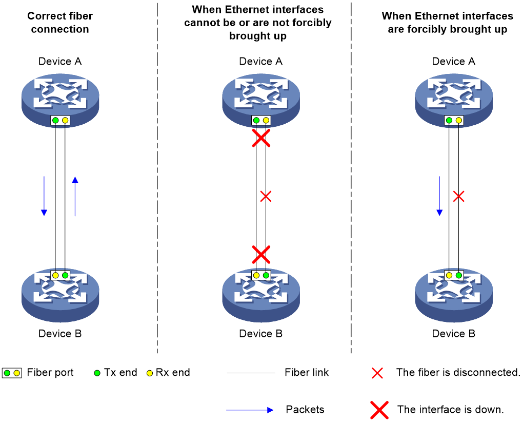
As shown in Figure 3, a fiber port uses separate fibers for transmitting and receiving packets. The physical state of the fiber port is up only when both transmit and receive fibers are physically connected. If one of the fibers is disconnected, the fiber port does not work.
To enable a fiber port to forward traffic over a single link, you can use the port up-mode command. This command forcibly brings up a fiber port, even when no fiber links or transceiver modules are present for the fiber port. When one fiber link is present and up, the fiber port can forward packets over the link unidirectionally.
Figure 3 Forcibly bring up a fiber port
Restrictions and guidelines
· Only 10-GE fiber ports operating in LAN mode, GE fiber ports, and 40-GE fiber ports support this feature. Copper ports, combo interfaces, and 100-GE fiber ports do not support this feature.
· The port up-mode, shutdown, and loopback commands are mutually exclusive.
· A fiber port forcibly brought up stays physically up whether or not a transceiver module or a fiber link is present for the port.
· A GE fiber port forcibly brought up cannot correctly forward traffic if it is installed with a fiber-to-copper converter, 100/1000-Mbps transceiver module, or 100-Mbps transceiver module. To solve the problem, use the undo port up-mode command on the fiber port.
Procedure
1. Enter system view.
system-view
2. Enter Ethernet interface view.
interface interface-type interface-number
3. Forcibly bring up the fiber port.
port up-mode
By default, a fiber port is not forcibly brought up, and the physical state of a fiber port depends on the physical state of the fibers.
Testing the cable connection of an Ethernet interface
|
|
IMPORTANT: If the link of an Ethernet interface is up, testing its cable connection will cause the link to go down and then come up. |
|
|
NOTE: Fiber ports do not support this feature. |
About this task
This feature tests the cable connection of an Ethernet interface and displays cable test result within 5 seconds. The test result includes the cable's status and some physical parameters. If any fault is detected, the test result shows the length from the local port to the faulty point.
Procedure
1. Enter system view.
system-view
2. Enter Ethernet interface view.
interface interface-type interface-number
3. Perform a test for the cable connected to the Ethernet interface.
virtual-cable-test
Configuring a Layer 3 Ethernet interface or subinterface
Setting the MTU for an Ethernet interface or subinterface
Restrictions and guidelines
The maximum transmission unit (MTU) of an Ethernet interface affects the fragmentation and reassembly of IP packets on the interface. Typically, you do not need to modify the MTU of an interface.
Procedure
1. Enter system view.
system-view
2. Enter interface view.
interface interface-type { interface-number | interface-number.subnumber }
3. Set the interface MTU.
mtu size
The default setting is 1500 bytes.
Setting the MAC address of an Ethernet interface or subinterface
About this task
In a network, when the Layer 3 Ethernet interfaces or subinterfaces of different devices have the same MAC address, the devices might fail to communicate correctly. To eliminate the MAC address conflicts, use the mac-address command to modify the MAC addresses of Layer 3 Ethernet interfaces or subinterfaces.
Additionally, when a Layer 3 Ethernet subinterface is created, it uses the MAC address of its main interface by default. As a result, all Layer 3 Ethernet subinterfaces of a Layer 3 Ethernet interface share the same MAC address. To set a different MAC address for a Layer 3 Ethernet subinterface, use the mac-address command.
Procedure
1. Enter system view.
system-view
2. Enter interface view.
interface interface-type { interface-number | interface-number.subnumber }
3. Set the interface MAC address.
mac-address mac-address
By default, no MAC address is set for a Layer 3 Ethernet interface.
Enabling destination MAC filtering
About this task
Typically, use the default settings.
With this feature enabled, when an interface receives a packet, the interface operates as follows:
· If the destination MAC address of the packet is the MAC address of the interface, the interface accepts and processes the packet.
· If the destination MAC address of the packet is not the MAC address of the interface, the interface drops the packet.
With this feature disabled, an interface accepts and processes a packet, without checking the destination MAC address of the packet.
Restrictions and guidelines
This feature takes effect only on Layer 3 Ethernet interfaces/subinterfaces, Layer 3 aggregate interfaces, and Layer 3 Reth interfaces. These interfaces are referred to as interfaces in this feature.
Procedure
1. Enter system view.
system-view
2. Enable destination MAC filtering.
mac-address-filter enable
By default, destination MAC filtering is enabled.
Display and maintenance commands
Execute display commands in any view and reset commands in user view.
|
Task |
Command |
|
Display interface traffic statistics. |
display counters { inbound | outbound } interface [ interface-type [ interface-number ] ] |
|
Display traffic rate statistics of interfaces in up state over the last statistics polling interval. |
display counters rate { inbound | outbound } interface [ interface-type [ interface-number ] ] |
|
Display the Ethernet module statistics. |
In standalone mode: display ethernet statistics slot slot-number [ cpu cpu-number ] In IRF mode: display ethernet statistics chassis chassis-number slot slot-number [ cpu cpu-number ] |
|
Display the operational and status information of the specified interfaces. |
display interface [ interface-type [ interface-number | interface-number.subnumber ] ] [ brief [ description | down ] ] |
|
Display information about dropped packets on the specified interfaces. |
display packet-drop interface [ interface-type [ interface-number ] ] |
|
Display information about storm control on the specified interfaces. |
display storm-constrain [ broadcast | multicast | unicast ] [ interface interface-type interface-number ] |
|
Clear interface statistics. |
reset counters interface [ interface-type [ interface-number | interface-number.subnumber ] ] |
|
Clear the Ethernet module statistics. |
In standalone mode: reset ethernet statistics [ slot slot-number [ cpu cpu-number ] ] In IRF mode: reset ethernet statistics [ chassis chassis-number slot slot-number [ cpu cpu-number ] ] |
|
Clear the statistics of dropped packets on the specified interfaces. |
reset packet-drop interface [ interface-type [ interface-number ] ] |
