- Table of Contents
-
- 15-WLAN Configuration Guide (FAT AP)
- 00-Preface
- 01-Compatibility of hardware and AP functionality
- 02-Radio management configuration
- 03-WLAN access configuration
- 04-WLAN security configuration
- 05-WLAN authentication configuration
- 06-WLAN QoS configuration
- 07-WLAN load balancing configuration
- 08-Band navigation configuration
- 09-WLAN multicast optimization configuration
- Related Documents
-
| Title | Size | Download |
|---|---|---|
| 06-WLAN QoS configuration | 236.06 KB |
Restrictions: Hardware compatibility with WLAN QoS
Setting EDCA parameters of AC-BE or AC-BK queues for clients
Setting EDCA parameters of AC-VI or AC-VO queues for clients
Configuring a port to trust packet priority for priority mapping
Configuring bandwidth guaranteeing
Configuring client rate limiting
Configuring service-template-based client rate limiting
Configuring client-type-based client rate limiting
Display and maintenance commands for WMM
WLAN QoS configuration examples
Example: Configuring basic WMM
Example: Configuring SVP mapping
Example: Configuring traffic differentiation
Example: Configuring bandwidth guaranteeing
Example: Configuring service-template-based client rate limiting
Configuring WLAN QoS
About WLAN QoS
An 802.11 network provides contention-based wireless access. To provide applications with QoS services, IEEE developed 802.11e for 802.11-based WLANs.
WLAN QoS features include WMM, SVP, bandwidth guaranteeing, and client rate limiting.
|
|
NOTE: The term "AP" in this document refers to MSR routers that support WLAN. For information about routers that support WLAN, see "Compatibility of MSR routers and AP functionality." |
WMM protocol
About this task
Wi-Fi Alliance defined the Wi-Fi Multimedia (WMM) standard to allow QoS provision devices of different vendors to interoperate. WMM enables a WLAN to provide QoS services, so that audio and video applications can have better performance in WLANs.
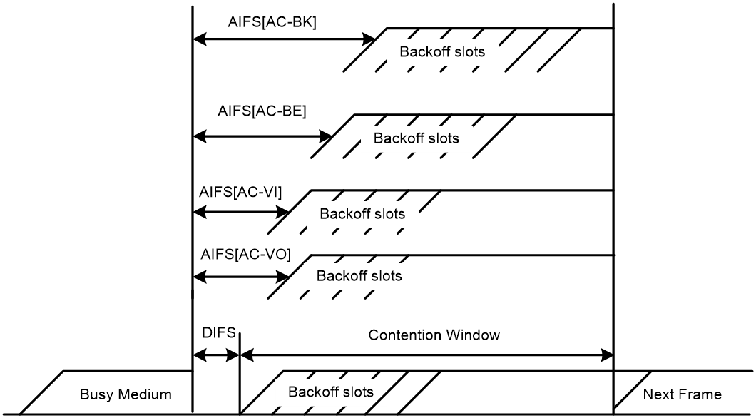
The Distributed Coordination Function (DCF) in 802.11 requires APs and clients to use the carrier sense multiple access with collision avoidance (CSMA/CA) access mechanism. APs or clients listen to the channel before they hold the channel for data transmission. When the specified idle duration of the channel times out, APs or clients randomly select a backoff slot within the contention window to perform backoff. The device that finishes backoff first gets the channel. With 802.11, all devices have the same idle duration and contention window. Therefore, they are equal when contending for a channel.
To provide QoS services, WMM divides data traffic into four ACs that have different priorities. Traffic in an AC with a high priority has a better chance to use the channel.
Terminology
· Enhanced distributed channel access—EDCA is a channel contention mechanism defined by WMM to preferentially transmit packets with high priority and allocate more bandwidth to such packets.
· Access category—WMM defines the following ACs: AC-VO for voice traffic, AC-VI for video traffic, AC-BE for best effort traffic, and AC-BK for background traffic. The priorities of the four ACs are in descending order.
· Connect Admission Control—CAC limits the number of clients that can use high-priority ACs (AC-VO and AC-VI) to guarantee enough bandwidth for these clients.
· Unscheduled automatic power save delivery—U-APSD is a power saving method defined by WMM to save client power.
EDCA parameters
· Arbitration inter-frame spacing number—In 802.11-based WLAN, each client has the same idle duration (DIFS), but WMM defines an idle duration for each AC. The idle duration increases as the AIFSN increases.
· Exponent form of CWmin/Exponent form of CWmax—ECWmin/ECWmax determines the backoff slots, which increase as the two values increase.
· Transmission opportunity limit—TXOP limit specifies the maximum time that a client can hold the channel after a successful contention. A larger value represents a longer time. If the value is 0, a client can send only one packet each time it holds the channel.
CAC admission policies
CAC requires a client to obtain permission from an AP before it can use a high-priority AC for transmission. This guarantees bandwidth for the clients that have gained access. CAC controls real time traffic (AC-VO and AC-VI traffic) but not common data traffic (AC-BE and AC-BK traffic).
If a client wants to use a high-priority AC (AC-VO or AC-VI), it must send a request to the AP. The AP returns a positive or negative response based on either of the following admission control policies:
· Channel usage-based admission policy—The AP calculates the channel occupation time of the existing high-priority AC queues and the requested AC queues within a time period, respectively. If the sum of the two values is smaller than or equal to the maximum hold time of the channel, the client can use the requested AC queue. If it is not, the request is rejected.
· Client-based admission policy—If the number of clients using high-priority AC queues is smaller than the maximum number of high-priority AC clients, the request is accepted. If it is not, the request is rejected. During calculation, a client is counted as one client if it is using both the AC-VO and AC-VI queues.
If the request is rejected because of lack of media resources, the AP assigns AC-BE to the client. Clients that already use high-priority AC queues will not be affected.
When calculating media resources, the AP takes requests before CAC is enabled into account. Whether subsequent requests for high-priority AC queues will be accepted is greatly restricted by the resource usage.
U-APSD power-save mechanism
U-APSD enables clients in sleep mode to wake up and receive the specified number of packets only after receiving a trigger packet. U-APSD improves the 802.11 APSD power saving mechanism.
U-APSD is automatically enabled after you enable WMM.
ACK policy
WMM defines the following ACK policies:
· Normal ACK—The recipient acknowledges each received unicast packet.
· No ACK—The recipient does not acknowledge received packets during wireless packet exchange. This policy improves the transmission efficiency in an environment where communication quality is strong and interference is weak. If communication quality deteriorates, this policy might increase the packet loss rate. For A-MPDU packets sent by 802.11n clients, the No ACK policy does not take effect.
SVP
SpectraLink Voice Priority (SVP) is developed by SpectraLink to provide QoS services for voice traffic.
Bandwidth guaranteeing
This feature provides the following functions:
· Ensures that traffic from all BSSs can pass through freely when the network is not congested.
· Ensures that each BSS can get the guaranteed bandwidth when the network is congested.
This feature improves bandwidth efficiency and maintains fair use of bandwidth among WLAN services. For example, you assign SSID1, SSID2, and SSID3 25%, 25%, and 50% of the total bandwidth. When the network is not congested, SSID1 can use all idle bandwidth in addition to its guaranteed bandwidth. When the network is congested, SSID1 is guaranteed with 25% of the bandwidth.
This feature applies only to AP-to-client traffic.
Client rate limiting
This feature prevents aggressive use of bandwidth by one client and ensures fair use of bandwidth among clients associated with the same AP.
You can configure either of the following modes for client rate limiting:
· Dynamic mode—Sets the total bandwidth shared by all clients. The rate limit for each client is the total rate divided by the number of online clients. For example, if the total rate is 10 Mbps and five clients are online, the rate limit for each client is 2 Mbps.
· Static mode—Sets the bandwidth that can be used by each client. When the rate limit multiplied by the number of associated clients exceeds the available bandwidth provided by the AP, the clients might not get the set bandwidth.
Protocols and standards
· 802.11e-2005, Amendment 8: Medium Access Control (MAC) Quality of Service Enhancements, IEEE Computer Society, 2005
· Wi-Fi, WMM Specification version 1.1, Wi-Fi Alliance, 2005
Restrictions: Hardware compatibility with WLAN QoS
For information about MSR routers that can offer WLAN services as fat APs, see "Compatibility of hardware and AP functionality."
Configuring WMM
WMM tasks at a glance
To configure WMM, perform the following tasks:
1. Enabling WMM
2. (Optional.) Setting EDCA parameters
3. (Optional.) Setting EDCA parameters of AC-BE or AC-BK queues for clients
4. (Optional.) Setting EDCA parameters of AC-VI or AC-VO queues for clients
5. (Optional.) Configuring a port to trust packet priority for priority mapping
Enabling WMM
About this task
All 802.11n and 802.11ac clients must support WMM. For 802.11n or 802.11ac clients to communicate with the associated AP, enable WMM when the radio operates in 802.11an, 802.11gn, or 802.11ac mode.
Procedure
1. Enter system view.
system-view
2. Enter radio interface view.
interface wlan-radio interface-number
3. Enable WMM.
wmm enable
By default, WMM is enabled.
Setting EDCA parameters
1. Enter system view.
system-view
2. Enter radio interface view.
interface wlan-radio interface-number
3. Set EDCA parameters.
edca radio { ac-be | ac-bk | ac-vi | ac-vo } { ack-policy { noack | normalack } | aifsn aifsn-value | ecw ecwmin ecwmin-value ecwmax ecwmax-value | txoplimit txoplimit-value } *
The default values for EDCA parameters are shown in Table 1.
Table 1 Default EDCA parameter values
|
AC |
AIFSN |
ECWmin |
ECWmax |
TXOP Limit |
|
AC-BK |
7 |
4 |
10 |
0 |
|
AC-BE |
3 |
4 |
6 |
0 |
|
AC-VI |
1 |
3 |
4 |
94 |
|
AC-VO |
1 |
2 |
3 |
47 |
Setting EDCA parameters of AC-BE or AC-BK queues for clients
1. Enter system view.
system-view
2. Enter radio interface view.
interface wlan-radio interface-number
3. Set EDCA parameters of AC-BE or AC-BK queues for clients.
edca client { ac-be | ac-bk } { aifsn aifsn-value | ecw ecwmin ecwmin-value ecwmax ecwmax-value | txoplimit txoplimit-value } *
The default values are shown in Table 2.
Table 2 Default EDCA parameter values of AC-BE or AC-BK queues for clients
|
AC |
AIFSN |
ECWmin |
ECWmax |
TXOP Limit |
|
AC-BK |
7 |
4 |
10 |
0 |
|
AC-BE |
3 |
4 |
10 |
0 |
Setting EDCA parameters of AC-VI or AC-VO queues for clients
1. Enter system view.
system-view
2. Enter radio interface view.
interface wlan-radio interface-number
3. Set EDCA parameters of AC-VI or AC-VO queues for clients.
edca client { ac-vi | ac-vo } { aifsn aifsn-value | cac { disable | enable } | ecw ecwmin ecwmin-value ecwmax ecwmax-value | txoplimit txoplimit-value } *
The default values are shown in Table 3.
Table 3 Default EDCA parameter values of AC-VI or AC-VO queues for clients
|
AC |
AIFSN |
ECWmin |
ECWmax |
TXOP Limit |
|
AC-VI |
2 |
3 |
4 |
94 |
|
AC-VO |
2 |
2 |
3 |
47 |
4. (Optional.) Configure the CAC policy.
cac policy { channelutilization [ channelutilization-value ] | client [ client-number ] }
By default, the client-based admission policy is used, and the maximum number of admitted clients is 20.
Configuring a port to trust packet priority for priority mapping
About this task
When the packet trust mode is disabled, an AP assigns the port priority to all packets for the service template.
Restrictions and guidelines
This feature takes effect only on uplink packets.
The port priority setting does not take effect if the trusted packet priority type is configured.
Procedure
1. Enter system view.
system-view
2. Enter service template view.
wlan service-template service-template-name
3. Configure the trusted packet priority type.
qos trust { dot11e | dscp }
By default, the port priority is trusted.
4. Set the port priority.
qos priority priority
By default, the port priority is 0.
Configuring SVP mapping
About this task
This feature assigns packets that have the protocol ID 119 in the IP header to the AC-VI or AC-VO queue to provide SVP packets with the specified priority. SVP does not require random backoff for SVP packets. Therefore, you can set both ECWmin and ECWmax to 0 when there are only SVP packets in the AC-VI or AC-VO queue.
When SVP mapping is disabled, SVP packets are assigned to the AC-BE queue.
Restrictions and guidelines
SVP mapping takes effect only on non-WMM clients.
Procedure
1. Enter system view.
system-view
2. Enter radio interface view.
interface wlan-radio interface-number
3. Enable SVP mapping.
svp map-ac { ac-vi | ac-vo }
By default, SVP mapping is disabled.
To disable SVP mapping, use the svp map-ac disable command.
Configuring bandwidth guaranteeing
4. Enter system view.
system-view
5. Set the maximum bandwidth for the specified radio mode.
wlan max-bandwidth { dot11a | dot11ac | dot11an | dot11b | dot11g | dot11gac | dot11gn } bandwidth
The following default settings apply:
¡ 30000 Kbps for dot11a and dot11g.
¡ 250000 Kbps for dot11an, dot11gn, and dot11gac
¡ 500000 Kbps for dot11ac.
¡ 7000 Kbps for dot11b.
6. Enter radio interface view.
interface wlan-radio interface-number
7. Configure bandwidth guaranteeing.
bandwidth-guarantee { disable | enable }
By default, bandwidth guaranteeing is disabled.
8. Set a guaranteed bandwidth percentage for the specified service template.
bandwidth-guarantee service-template service-template-name percent percent
By default, no guaranteed bandwidth percentage is set for a service template.
Configuring client rate limiting
About client rate limiting
By rate limit method, you can configure service-template-based, radio-based, or client-type-based client rate limiting. By rate limit mode, you can configure the dynamic or static mode for client rate limiting.
If more than one method and mode are configured, all settings take effect. The rate for a client will be limited to the minimum value among all the client rate limiting settings.
Restrictions and guidelines
Service-template-based client rate limiting takes effect on all clients associated with the same service template.
Client-type-based client rate limiting takes effect on all clients of the specified protocol.
Configuring service-template-based client rate limiting
1. Enter system view.
system-view
2. Enter service template view.
wlan service-template service-template-name
3. Configure service-template-based client rate limiting.
client-rate-limit { inbound | outbound } mode { dynamic cir cir [ min min-cir ] [ max max-cir ] | static cir cir } [ cbs cbs ]
By default, service-template-based client rate limiting is not configured.
Configuring client-type-based client rate limiting
1. Enter system view.
system-view
2. Configure client-type-based client rate limiting.
wlan client-rate-limit { dot11a | dot11ac | dot11an | dot11b | dot11g | dot11gac | dot11gn } { inbound | outbound } cir cir [ cbs cbs ]
By default, client-type-based client rate limiting is not configured.
Display and maintenance commands for WMM
Execute display commands in any view and reset commands in user view.
|
Task |
Command |
|
Display WMM statistics for clients. |
display wlan wmm client [ interface wlan-radio interface-number | mac-address mac-address ] |
|
Display WMM statistics for radios. |
display wlan wmm radio [ interface wlan-radio interface-number ] |
|
Clear WMM statistics for clients. |
reset wlan wmm client [ interface wlan-radio interface-number | mac-address mac-address ] |
|
Clear WMM statistics for radios. |
reset wlan wmm radio [ interface wlan-radio interface-number ] |
WLAN QoS configuration examples
Example: Configuring basic WMM
Network configuration
As shown in Figure 2, enable WMM on the AP so that the AP and the client can prioritize the traffic.

Procedure
# Create a service template named market, set the SSID to market, and enable the service template.
<AP> system-view
[AP] wlan service-template market
[AP-wlan-st-market] ssid market
[AP-wlan-st-market] service-template enable
[AP-wlan-st-market] quit
# Bind service template market to WLAN-Radio 0/0.
[AP] interface wlan-radio 0/0
[AP-WLAN-Radio0/0] undo shutdown
[AP-WLAN-Radio0/0] service-template market
# Enable WMM.
[AP-WLAN-Radio0/0] wmm enable
[AP-WLAN-Radio0/0] quit
Verifying the configuration
# Display WMM statistics for radios.
[AP] display wlan wmm radio
Radio : 1
Client EDCA updates : 0
QoS mode : WMM
WMM status : Enabled
Radio max AIFSN : 15 Radio max ECWmin : 0
Radio max TXOPLimit : 32767 Radio max ECWmax : 0
CAC information
Clients accepted : 0
Voice : 0
Video : 0
Total request medium time(μs) : 0
Voice(μs) : 0
Video(μs) : 0
Calls rejected due to insufficient resources : 0
Calls rejected due to invalid parameters : 0
Calls rejected due to invalid medium time : 0
Calls rejected due to invalid delay bound : 0
Example: Configuring CAC
Network configuration
As shown in Figure 3, configure CAC to allow a maximum of 10 clients to use the AC-VO and AC-VI queues.

Procedure
# Create a service template named market, set the SSID to market, and enable the service template.
<AP> system-view
[AP] wlan service-template market
[AP-wlan-st-market] ssid market
[AP-wlan-st-market] service-template enable
[AP-wlan-st-market] quit
# Bind service template market to WLAN-Radio 0/0.
[AP] interface wlan-radio 0/0
[AP-WLAN-Radio0/0] undo shutdown
[AP-WLAN-Radio0/0] service-template market
# Enable WMM for AC-VO and AC-VI queues, and configure a CAC policy to limit the number of clients to 10.
[AP-WLAN-Radio0/0] wmm enable
[AP-WLAN-Radio0/0] edca client ac-vo cac enable
[AP-WLAN-Radio0/0] edca client ac-vi cac enable
[AP-WLAN-Radio0/0] cac policy client 10
Verifying the configuration
# Assume that a client requests to use a high-priority AC queue (AC-VO or AC-VI). Verify the following information:
· If the number of clients using high-priority AC queues is smaller than the maximum number of high-priority AC clients (10 in this example), the request is accepted.
· If the number of clients using high-priority AC queues is equal to the maximum number of high-priority AC clients (10 in this example), the request is rejected. The AP decreases the priority of packets from the client.
Example: Configuring SVP mapping
Network configuration
As shown in Figure 4, configure SVP mapping on the AP to assign SVP packets to the AC-VO queue. Set ECWmin and ECWmax to 0 for the AC-VO queue of the AP.

Procedure
# Create a service template named market, set the SSID to market, and enable the service template.
<AP> system-view
[AP] wlan service-template market
[AP-wlan-st-market] ssid market
[AP-wlan-st-market] service-template enable
[AP-wlan-st-market] quit
# Bind service template market to WLAN-Radio 0/0.
[AP] interface wlan-radio 0/0
[AP-WLAN-Radio0/0] undo shutdown
[AP-WLAN-Radio0/0] service-template market
# Enable WMM.
[AP-WLAN-Radio0/0] wmm enable
# Assign SVP packets to the AC-VO queue, and set EDCA parameters of AC-VO queues for clients.
[AP-WLAN-Radio0/0] svp map-ac ac-vo
[AP-WLAN-Radio0/0] edca client ac-vo ecw ecwmin 0 ecwmax 0
Verifying the configuration
# Verify that the AC assigns SVP packets to the AC-VO queue if a non-WMM client comes online and sends SVP packets to the AC.
Example: Configuring traffic differentiation
Network configuration
As shown in Figure 5, configure priority mapping on the AP to add 802.11 packets from the client to the AC-VO queue.

Procedure
# Create a service template named market, set the SSID to market, and enable the service template.
<AP> system-view
[AP] wlan service-template market
[AP-wlan-st-market] ssid market
[AP-wlan-st-market] service-template enable
# Set the 802.11e priority of 802.11 packets from the client to 7.
[AP-wlan-st-market] qos priority 7
[AP-wlan-st-market] quit
# Bind service template market to WLAN-Radio 0/0.
[AP] interface wlan-radio 0/0
[AP-WLAN-Radio0/0] undo shutdown
[AP-WLAN-Radio0/0] service-template market
# Enable WMM.
[AP-WLAN-Radio0/0] wmm enable
[AP-WLAN-Radio0/0] quit
Verifying the configuration
# Perform the following tasks on the AP:
· Execute the terminal monitor command to enable monitoring of logs on the current terminal.
· Execute the terminal debugging command to enable display of debug information on the current terminal.
· Execute the debugging wlan wmm all command to enable all the WMM debugging features.
# Ping the client and the switch on the AP to verify that the network connections are correct.
# Verify that the priority of packets from the client to the AP is changed to 7 and the priority of packets from the AP to the client is not changed.
Example: Configuring bandwidth guaranteeing
Network configuration
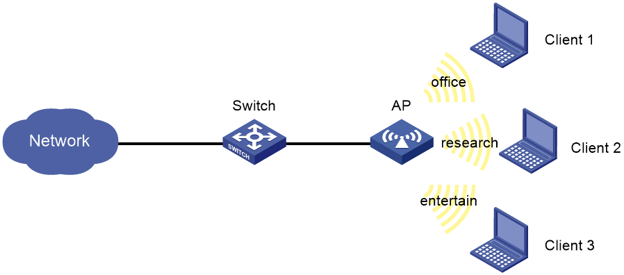
As shown in Figure 6, Clients 1, 2, and 3 access the network through SSIDs research, office, and entertain, respectively.
For the network to operate correctly, guarantee 20% of the bandwidth for SSID office, 80% for research, and none for entertain.
Procedure
# Create a service template named office, set the SSID to office, and enable the service template.
<AP> system-view
[AP] wlan service-template office
[AP-wlan-st-office] ssid office
[AP-wlan-st-office] service-template enable
[AP-wlan-st-office] quit
# Create a service template named research, set the SSID to research, and enable the service template.
[AP] wlan service-template research
[AP-wlan-st-research] ssid research
[AP-wlan-st-research] service-template enable
[AP-wlan-st-research] quit
# Create a service template named entertain, set the SSID to entertain, and enable the service template.
[AP] wlan service-template entertain
[AP-wlan-st-entertain] ssid entertain
[AP-wlan-st-entertain] service-template enable
[AP-wlan-st-entertain] quit
# Set the maximum bandwidth to 10000 Kbps for the 802.11ac radio.
[AP] wlan max-bandwidth dot11ac 10000
# Bind service templates office, research, and entertain to WLAN-Radio0/0.
[AP] interface wlan-radio 0/0
[AP-WLAN-Radio0/0] undo shutdown
[AP-WLAN-Radio0/0] service-template office
[AP-WLAN-Radio0/0] service-template research
[AP-WLAN-Radio0/0] service-template entertain
# Enable bandwidth guaranteeing.
[AP-WLAN-Radio0/0] bandwidth-guarantee enable
# Set the guaranteed bandwidth percentage to 20% for service template office and 80% for service template research.
[AP-WLAN-Radio0/0] bandwidth-guarantee service-template office percent 20
[AP-WLAN-Radio0/0] bandwidth-guarantee service-template research percent 80
[AP-WLAN-Radio0/0] return
Verifying the configuration
# Verify that the rate of traffic from the AP to any client is not limited when the total traffic rate is lower than 10000 Kbps.
# Send traffic from the AP to Client 1 and Client 2 at a rate of over 2000 Kbps and over 8000 Kbps, respectively, to verify the following items:
· The AP sends traffic to Client 1 at 2000 Kbps.
· The AP sends traffic to Client 2 at 8000 Kbps.
· The rate of traffic from the AP to Client 3 is limited.
Example: Configuring service-template-based client rate limiting
Network configuration
As shown in Figure 7, perform the following tasks on the AP:
· Configure static mode client rate limiting to limit the rate of incoming client traffic.
· Configure dynamic mode client rate limiting to limit the rate of outgoing client traffic.

Procedure
# Create a service template named service, and set its SSID to service.
<AP> system-view
[AP] wlan service-template service
[AP-wlan-st-service] ssid service
# Limit the rate of incoming traffic to 8000 Kbps in static mode, and limit the rate of outgoing traffic to 8000 Kbps in dynamic mode.
[AP-wlan-st-service] client-rate-limit inbound mode static cir 8000
[AP-wlan-st-service] client-rate-limit outbound mode dynamic cir 8000
[AP-wlan-st-service] service-template enable
[AP-wlan-st-service] quit
# Bind service template service to the interface WLAN-Radio0/0.
[AP] interface wlan-radio 0/0
[AP-WLAN-Radio0/0] undo shutdown
[AP-WLAN-Radio0/0] service-template service
[AP-WLAN-Radio0/0] return
