- Table of Contents
- Related Documents
-
| Title | Size | Download |
|---|---|---|
| 03-IPsec configuration | 408.91 KB |
IPv6 routing protocol-based IPsec
IPsec policy and IPsec profile
Restrictions and guidelines: IPsec configuration
ACL-based IPsec tasks at a glance
Configuring an IPsec transform set
Configuring a manual IPsec policy
Configuring an IKE-based IPsec policy
Applying an IPsec policy to an interface
Enabling ACL checking for de-encapsulated packets
Binding a source interface to an IPsec policy
Configuring IPsec for IPv6 routing protocols
IPsec protection for IPv6 routing protocols tasks at a glance
Configuring a manual IPsec profile
Applying the IPsec profile to an IPv6 routing protocol
Configuring IPsec anti-replay redundancy
Configuring the global IPsec SA lifetime and idle timeout
Configuring IPsec fragmentation
Configuring the DF bit of IPsec packets
Setting the maximum number of IPsec tunnels
Enabling logging for IPsec packets
Enabling logging for IPsec negotiation
Configuring SNMP notifications for IPsec
Verifying and maintaining IPsec
Displaying IPsec configuration and statistics
Example: Configuring a manual mode IPsec tunnel for IPv4 packets
Configuring IPsec
About IPsec
IP Security (IPsec) is defined by the IETF to provide interoperable, high-quality, cryptography-based security for IP communications. It is a Layer 3 VPN technology that transmits data in a secure channel established between two endpoints (such as two security gateways). Such a secure channel is usually called an IPsec tunnel.
IPsec framework
IPsec is a security framework that has the following protocols and algorithms:
· Authentication Header (AH).
· Encapsulating Security Payload (ESP).
· Internet Key Exchange (IKE).
· Algorithms for authentication and encryption.
AH and ESP are security protocols that provide security services. IKE performs automatic key exchange. For more information about IKE, see "Configuring IKE."
IPsec security services
IPsec provides the following security services for data packets in the IP layer:
· Confidentiality—The sender encrypts packets before transmitting them over the Internet, protecting the packets from being eavesdropped en route.
· Data integrity—The receiver verifies the packets received from the sender to make sure they are not tampered with during transmission.
· Data origin authentication—The receiver verifies the authenticity of the sender.
· Anti-replay—The receiver examines packets and drops outdated and duplicate packets.
Benefits of IPsec
IPsec delivers the following benefits:
· Reduced key negotiation overhead and simplified maintenance by supporting the IKE protocol. IKE provides automatic key negotiation and automatic IPsec security association (SA) setup and maintenance.
· Good compatibility. You can apply IPsec to all IP-based application systems and services without modifying them.
· Encryption on a per-packet rather than per-flow basis. Per-packet encryption allows for flexibility and greatly enhances IP security.
Security protocols
IPsec comes with two security protocols, AH and ESP. They define how to encapsulate IP packets and the security services that they can provide.
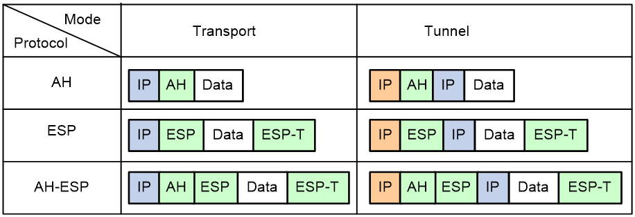
· AH (protocol 51) defines the encapsulation of the AH header in an IP packet, as shown in Figure 3. AH can provide data origin authentication, data integrity, and anti-replay services to prevent data tampering, but it cannot prevent eavesdropping. Therefore, it is suitable for transmitting non-confidential data. Authentication algorithms supported by AH include HMAC-MD5 and HMAC-SHA1.
· ESP (protocol 50) defines the encapsulation of the ESP header and trailer in an IP packet, as shown in Figure 3. ESP can provide data encryption, data origin authentication, data integrity, and anti-replay services. Unlike AH, ESP can guarantee data confidentiality because it can encrypt the data before encapsulating the data to IP packets. ESP-supported encryption algorithms include DES, 3DES, and AES, and authentication algorithms include HMAC-MD5 and HMAC-SHA1.
Both AH and ESP provide authentication services, but the authentication service provided by AH is stronger. In practice, you can choose either or both security protocols. When both AH and ESP are used, an IP packet is encapsulated first by ESP and then by AH.
Encapsulation modes
IPsec supports the following encapsulation modes: transport mode and tunnel mode.
Transport mode
The security protocols protect the upper layer data of an IP packet. Only the transport layer data is used to calculate the security protocol headers. The calculated security protocol headers and the encrypted data (only for ESP encapsulation) are placed after the original IP header. You can use the transport mode when end-to-end security protection is required (the secured transmission start and end points are the actual start and end points of the data). The transport mode is typically used for protecting host-to-host communications, as shown in Figure 1.
Figure 1 IPsec protection in transport mode

Tunnel mode
The security protocols protect the entire IP packet. The entire IP packet is used to calculate the security protocol headers. The calculated security protocol headers and the encrypted data (only for ESP encapsulation) are encapsulated in a new IP packet. In this mode, the encapsulated packet has two IP headers. The inner IP header is the original IP header. The outer IP header is added by the network device that provides the IPsec service. You must use the tunnel mode when the secured transmission start and end points are not the actual start and end points of the data packets (for example, when two gateways provide IPsec but the data start and end points are two hosts behind the gateways). The tunnel mode is typically used for protecting gateway-to-gateway communications, as shown in Figure 2.
Figure 2 IPsec protection in tunnel mode

Figure 3 shows how the security protocols encapsulate an IP packet in different encapsulation modes.
Figure 3 Security protocol encapsulations in different modes
Security association
About this task
A security association (SA) is an agreement negotiated between two communicating parties called IPsec peers. An SA includes the following parameters for data protection:
· Security protocols (AH, ESP, or both).
· Encapsulation mode (transport mode or tunnel mode).
· Authentication algorithm (HMAC-MD5 or HMAC-SHA1).
· Encryption algorithm (DES, 3DES, or AES).
· Shared keys and their lifetimes.
An SA is unidirectional. At least two SAs are needed to protect data flows in a bidirectional communication. If two peers want to use both AH and ESP to protect data flows between them, they construct an independent SA for each protocol in each direction.
An SA is uniquely identified by a triplet, which consists of the security parameter index (SPI), destination IP address, and security protocol identifier. An SPI is a 32-bit number. It is transmitted in the AH/ESP header.
SA setup
An SA can be set up manually or through IKE.
· Manual mode—Configure all parameters for the SA through commands. This configuration mode is complex and does not support some advanced features (such as periodic key update), but it can implement IPsec without IKE. This mode is mainly used in small and static networks or when the number of IPsec peers in the network is small.
· IKE negotiation mode—The peers negotiate and maintain the SA through IKE. This configuration mode is simple and has good expansibility. As a best practice, set up SAs through IKE negotiations in medium- and large-scale dynamic networks.
SA aging
A manually configured SA never ages out.
An IKE-created SA has a lifetime and will be deleted when its lifetime timer expires.
Before the SA lifetime timer expires, IKE negotiates a new SA, which takes over immediately after its creation. The interval from the creation of an SA to the negotiation of a new SA is the SA's soft lifetime.
The SA soft lifetime is calculated as follows: SA soft lifetime = SA lifetime – SA soft lifetime buffer. If the SA soft lifetime buffer is not configured, the system calculates a default SA soft lifetime based on the SA lifetime.
The lifetime of an IKE-created SA comes in two types:
· Time-based lifetime—Defines how long the SA can exist after it is created.
· Traffic-based lifetime—Defines the maximum traffic that the SA can process.
If both lifetime timers are configured for an SA, the SA is deleted when either of the lifetime timers expires.
Authentication and encryption
Authentication algorithms
IPsec uses hash algorithms to perform authentication. A hash algorithm produces a fixed-length digest for an arbitrary-length message. IPsec peers respectively calculate message digests for each packet. The receiver compares the local digest with that received from the sender. If the digests are identical, the receiver considers the packet intact and the sender's identity valid. IPsec supports Hash-based Message Authentication Code (HMAC) based authentication algorithms, including HMAC-MD5 and HMAC-SHA. HMAC-MD5 is faster but less secure than HMAC-SHA.
Encryption algorithms
IPsec uses symmetric encryption algorithms, which encrypt and decrypt data by using the same keys. The following encryption algorithms are available for IPsec on the device:
· DES—Encrypts a 64-bit plaintext block with a 56-bit key. DES is the least secure but the fastest algorithm.
· 3DES—Encrypts plaintext data with three 56-bit DES keys. The key length totals up to 168 bits. It provides moderate security strength and is slower than DES.
· AES—Encrypts plaintext data with a 128-bit, 192-bit, or 256-bit key. AES provides the highest security strength and is slower than 3DES.
IPsec-protected traffic
IPsec tunnels can protect the following types of traffic:
· Packets that match specific ACLs.
· Packets of IPv6 routing protocols.
Two peers use security policies (IPsec policies or IPsec profiles) to protect packets between them. A security policy defines the range of packets to be protected by IPsec and the security parameters used for the protection. For more information about IPsec policies and IPsec profiles, see "IPsec policy and IPsec profile."
The following information describes how IPsec protects packets:
· When an IPsec peer identifies the packets to be protected according to the security policy, it sets up an IPsec tunnel and sends the packet to the remote peer through the tunnel. The IPsec tunnel can be manually configured beforehand, or it can be set up through IKE negotiation triggered by the packet. The IPsec tunnels are actually the IPsec SAs. The inbound packets are protected by the inbound SA, and the outbound packets are protected by the outbound SA.
· When the remote IPsec peer receives the packet, it drops, de-encapsulates, or directly forwards the packet according to the configured security policy.
ACL-based IPsec
To implement ACL-based IPsec, configure an ACL to define the data flows to be protected, specify the ACL in an IPsec policy, and then apply the IPsec policy to an interface. You can apply an IPsec policy to physical interfaces such as serial interfaces and Ethernet interfaces, or virtual interfaces such as tunnel interfaces and virtual template interfaces.
ACL-based IPsec works as follows:
· When packets sent by the interface match a permit rule of the ACL, the packets are protected by the outbound IPsec SA and encapsulated with IPsec.
· When the interface receives an IPsec packet destined for the local device, it searches for the inbound IPsec SA according to the SPI in the IPsec packet header for de-encapsulation. If the de-encapsulated packet matches a permit rule of the ACL, the device processes the packet. If the de-encapsulated packet does not match any permit rule of the ACL, the device drops the packet.
The device supports the following data flow protection modes:
· Standard mode—One IPsec tunnel protects one data flow. The data flow permitted by an ACL rule is protected by one IPsec tunnel that is established solely for it.
· Aggregation mode—One IPsec tunnel protects all data flows permitted by all the rules of an ACL. This mode is only used to communicate with old-version devices.
· Per-host mode—One IPsec tunnel protects one host-to-host data flow. One host-to-host data flow is identified by one ACL rule and protected by one IPsec tunnel established solely for it. This mode consumes more system resources when multiple data flows exist between two subnets to be protected.
IPv6 routing protocol-based IPsec
You can implement IPv6 routing protocol-based IPsec by binding an IPsec profile to an IPv6 routing protocol. All packets of the protocol are encapsulated with IPsec. Supported IPv6 routing protocols include OSPFv3, IPv6 BGP, and RIPng.
All packets of the applications that are not bound to IPsec and the IPsec packets that failed to be de-encapsulated are dropped.
In one-to-many communication scenarios, you must configure the IPsec SAs for an IPv6 routing protocol in manual mode because of the following reasons:
· The automatic key exchange mechanism protects communications between two points. In one-to-many communication scenarios, automatic key exchange cannot be implemented.
· One-to-many communication scenarios require that all the devices use the same SA parameters (SPI and key) to receive and send packets. IKE negotiated SAs cannot meet this requirement.
IPsec policy and IPsec profile
IPsec policies and IPsec profiles define the parameters used to establish IPsec tunnels between two peers and the range of packets to be protected.
IPsec policy
An IPsec policy is a set of IPsec policy entries that have the same name but different sequence numbers.
An IPsec policy contains the following settings:
· An ACL that defines the range of data flows to be protected.
· An IPsec transform set that defines the security parameters used for IPsec protection.
· IPsec SA establishment mode.
Supported IPsec SA establishment modes are manual configuration and IKE negotiation.
· Local and remote IP addresses that define the start and end points of the IPsec tunnel.
In the same IPsec policy, an IPsec policy entry with a smaller sequence number has a higher priority. When sending a packet, the interface applied with an IPsec policy looks through the IPsec policy's entries in ascending order of sequence numbers. If the packet matches the ACL of an IPsec policy entry, the interface encapsulates the packet according to the IPsec policy entry. If no match is found, the interface sends the packet out without IPsec protection.
When the interface receives an IPsec packet destined for the local device, it searches for the inbound IPsec SA according to the SPI in the IPsec packet header for de-encapsulation. If the de-encapsulated packet matches a permit rule of the ACL, the device processes the packet. If the de-encapsulated packet does not match a permit rule of the ACL, the device drops the packet.
IPsec profile
An IPsec profile has similar settings as an IPsec policy. It is uniquely identified by a name and does not support ACL configuration.
An IPsec profile is used to protect IPv6 routing protocols. It specifies the IPsec transform set used for protecting data flows, and the SPIs and keys used by the SAs.
IPsec RRI
IPsec Reverse Route Injection (RRI) enables an IPsec tunnel gateway to automatically add and delete static routes destined for the protected private networks. It automatically adds the static routes when the IPsec SAs are established and deletes the static routes when the IPsec SAs are deleted. This greatly reduces the static route configuration work load on the gateway and increases the scalability of the IPsec VPN.
IPsec RRI is applicable to gateways that must provide many IPsec tunnels (for example, a headquarters gateway).
As shown in Figure 4, the traffic between the enterprise center and the branches are protected by IPsec. The gateway at the enterprise center is configured with static routes to route traffic to the IPsec-protected interfaces. It is difficult to add or modify static routes on the gateway at the enterprise center if the IPsec VPN has a large number of branches or if the network structure changes.
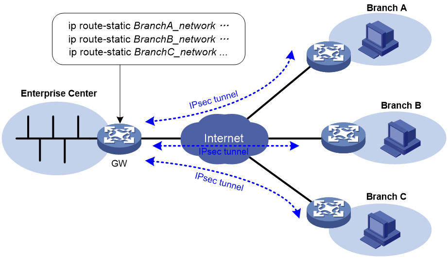
After you can enable IPsec RRI on the gateway, the gateway automatically adds a static route to the routing table each time an IPsec tunnel is established. The destination IP address is the protected private network. The next hop IP address can be the remote IP address of the IPsec tunnel (default) or a user-defined next hop IP address. Traffic destined for the peer end is routed to the IPsec tunnel interface and thereby protected by IPsec.
You can advertise the static routes created by IPsec RRI in the internal network, and the internal network device can use them to forward traffic in the IPsec VPN.
You can set preferences for the static routes created by IPsec RRI to implement flexible route management. For example, you can set the same preference for multiple routes to the same destination to implement load sharing, or you can set different preferences to implement route backup.
You can also set tags for the static routes created by IPsec RRI to implement flexible route control through routing policies.
Protocols and standards
· RFC 2401, Security Architecture for the Internet Protocol
· RFC 2402, IP Authentication Header
· RFC 2406, IP Encapsulating Security Payload
· RFC 4552, Authentication/Confidentiality for OSPFv3
Security strength
By default, the device provides low encryption. To obtain high encryption, you must install the Strong Cryptography feature license. This feature provides stronger cryptography, additional IPsec tunnels, and higher encryption performance. For more information about obtaining the Strong Cryptography feature license, see the release notes or contact your H3C sales representative.
Support for features, commands, and parameters depends on the cryptography capability.
Restrictions and guidelines: IPsec configuration
Typically, IKE uses UDP port 500 for communication, and AH and ESP use the protocol numbers 51 and 50, respectively. Make sure traffic of these protocols is not denied on the interfaces with IKE or IPsec configured.
Implementing ACL-based IPsec
ACLs for IPsec take effect only on traffic that is generated by the device and traffic that is destined for the device. They do not take effect on traffic forwarded through the device. For example, an ACL-based IPsec tunnel can protect log messages the device sends to a log server, but it does not protect data flows and voice flows that are forwarded by the device.
ACL-based IPsec tasks at a glance
To configure ACL-based IPsec, perform the following tasks:
2. Configuring an IPsec transform set
3. Configuring an IPsec policy
Choose one of the following tasks:
¡ Configuring a manual IPsec policy
¡ Configuring an IKE-based IPsec policy
4. Applying an IPsec policy to an interface
5. (Optional.) Configuring accessibility features for ACL-based IPsec
¡ Enabling ACL checking for de-encapsulated packets
¡ Configuring IPsec anti-replay
¡ Configuring IPsec anti-replay redundancy
¡ Binding a source interface to an IPsec policy
¡ Configuring the DF bit of IPsec packets
¡ Configuring the global IPsec SA lifetime and idle timeout
¡ Configuring IPsec fragmentation
¡ Setting the maximum number of IPsec tunnels
6. (Optional.) Configuring logging and SNMP notification for IPsec.
¡ Enabling logging for IPsec packets
¡ Enabling logging for IPsec negotiation
¡ Configuring SNMP notifications for IPsec
Configuring an ACL
IPsec uses ACLs to identify the traffic to be protected.
Keywords in ACL rules
An ACL is a collection of ACL rules. Each ACL rule is a deny or permit statement. A permit statement identifies a data flow protected by IPsec, and a deny statement identifies a data flow that is not protected by IPsec. IPsec compares a packet against the ACL rules and processes the packet according to the first rule it matches.
· Each ACL rule matches both the outbound traffic and the returned inbound traffic. Suppose there is a rule rule 0 permit ip source 1.1.1.0 0.0.0.255 destination 2.2.2.0 0.0.0.255. This rule matches both traffic from 1.1.1.0 to 2.2.2.0 and traffic from 2.2.2.0 to 1.1.1.0.
· In the outbound direction, if a permit statement is matched, IPsec considers that the packet requires protection and continues to process it. If a deny statement is matched or no match is found, IPsec considers that the packet does not require protection and delivers it to the next module.
· In the inbound direction:
¡ Non-IPsec packets that match a permit statement are dropped.
¡ IPsec packets destined for the device itself are de-encapsulated. By default, the de-encapsulated packets are compared against the ACL rules. Only those that match a permit statement are processed. Other packets are dropped. If ACL checking for de-encapsulated IPsec packets is disabled, the de-encapsulated packets are not compared against the ACL rules and are directly processed by other modules.
When defining ACL rules for IPsec, follow these guidelines:
· Permit only data flows that need to be protected and use the any keyword with caution. With the any keyword specified in a permit statement, all outbound traffic matching the permit statement will be protected by IPsec. All inbound IPsec packets matching the permit statement will be received and processed, but all inbound non-IPsec packets will be dropped. This will cause all the inbound traffic that does not need IPsec protection to be dropped.
· Avoid statement conflicts in the scope of IPsec policy entries. When creating a deny statement, be careful with its match scope and match order relative to permit statements. The policy entries in an IPsec policy have different match priorities. ACL rule conflicts between them are prone to cause mistreatment of packets. For example, when configuring a permit statement for an IPsec policy entry to protect an outbound traffic flow, you must avoid the situation that the traffic flow matches a deny statement in a higher priority IPsec policy entry. Otherwise, the packets will be sent out as normal packets. If they match a permit statement at the receiving end, they will be dropped by IPsec.
The following example shows how an improper statement causes unexpected packet dropping. Only the ACL-related configuration is presented.
Assume Device A is connected to subnet 1.1.2.0/24 and Device B is connected to subnet 3.3.3.0/24, and the IPsec policy configuration on Device A and Device B is as follows:
· IPsec configuration on Device A:
acl advanced 3000
rule 0 permit ip source 1.1.1.0 0.0.0.255 destination 2.2.2.0 0.0.0.255
rule 1 deny ip
acl advanced 3001
rule 0 permit ip source 1.1.2.0 0.0.0.255 destination 3.3.3.0 0.0.0.255
rule 1 deny ip
#
ipsec policy testa 1 isakmp <---IPsec policy entry with a higher priority
security acl 3000
ike-profile aa
transform-set 1
#
ipsec policy testa 2 isakmp <---IPsec policy entry with a lower priority
security acl 3001
ike-profile bb
transform-set 1
· IPsec configuration on Device B:
acl advanced 3001
rule 0 permit ip source 3.3.3.0 0.0.0.255 destination 1.1.2.0 0.0.0.255
rule 1 deny ip
#
ipsec policy testb 1 isakmp
security acl 3001
ike-profile aa
transform-set 1
On Device A, apply the IPsec policy testa to the outbound interface of Device A. The IPsec policy contains two policy entries, testa 1 and testa 2. The ACLs used by the two policy entries each contain a rule that matches traffic from 1.1.2.0/24 to 3.3.3.0/24. The one used in the policy entry testa 1 is a deny statement and the one used in the policy entry testa 2 is a permit statement. Because testa 1 is matched prior to testa 2, traffic from 1.1.2.0/24 to 3.3.3.0/24 will match the deny statement and be sent as normal traffic. When the traffic arrives at Device B, the traffic matches rule 0 (a permit statement) in ACL 3001 used in the applied IPsec policy testb. Because non-IPsec traffic that matches a permit statement must be dropped on the inbound interface, Device B drops the traffic.
To make sure subnet 1.1.2.0/24 can access subnet 3.3.3.0/24, you can delete the deny rule in ACL 3000 on Device A.
Mirror image ACLs
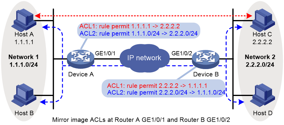
To make sure SAs can be set up and the traffic protected by IPsec can be processed correctly between two IPsec peers, create mirror image ACLs on the IPsec peers. As shown in Figure 5, ACL rules on Device B are mirror images of the rules on Device A. In this way, SAs can be created successfully for the traffic between Host A and Host C and for the traffic between Network 1 and Network 2.
If the ACL rules on IPsec peers do not form mirror images of each other, SAs can be set up only when both of the following requirements are met:
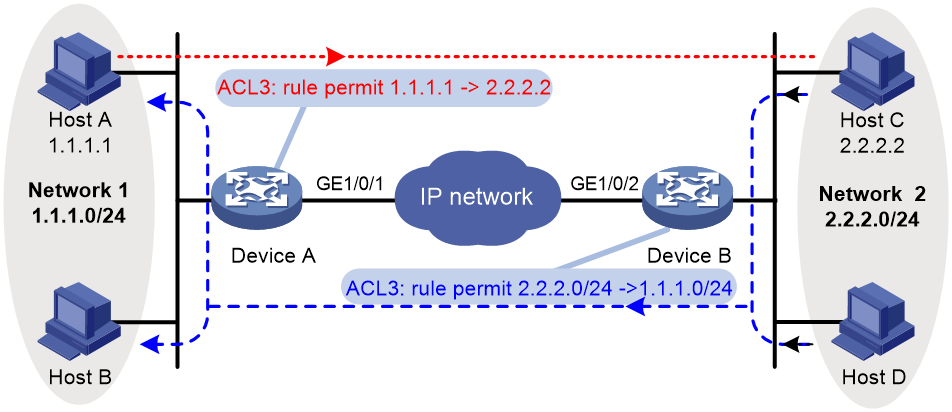
· The range specified by an ACL rule on one peer is covered by its counterpart ACL rule on the other peer. As shown in Figure 6, the range specified by the ACL rule configured on Device A is covered by its counterpart on Device B.
· The peer with the narrower rule initiates SA negotiation. If a wider ACL rule is used by the SA initiator, the negotiation request might be rejected because the matching traffic is beyond the scope of the responder. As shown in Figure 6, the SA negotiation initiated by Host A to Host C is accepted but the SA negotiations from Host C to Host A, from Host C to Host B, and from Host D to Host A are rejected.
Figure 6 Non-mirror image ACLs
ACL for MPLS L3VPN IPsec protection
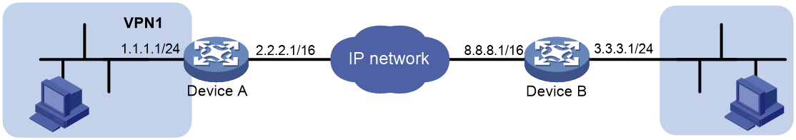
To use IPsec to protect the data of an MPLS L3VPN, you must specify the VPN instance for the protected data in the ACL.
As shown in Figure 7, to protect traffic of VPN1 by using IPsec, you must configure the ACL on Device A as follows:
#
acl advanced 3400
rule 0 permit ip vpn-instance vpn1 source 1.1.1.0 0.0.0.255 destination 3.3.3.0 0.0.0.255
#
In addition, you must specify VPN1 as the inside VPN instance in the IKE profile.
#
ike profile vpn1
keychain vpn1
match remote identity address 8.8.8.1 255.255.255.255
inside-vpn vpn-instance vpn1
#
Configuring an IPsec transform set
About this task
An IPsec transform set, part of an IPsec policy, defines the security parameters for IPsec SA negotiation, including the security protocol, encryption algorithms, and authentication algorithms.
Restrictions and guidelines
Changes to an IPsec transform set affect only SAs negotiated after the changes. To apply the changes to existing SAs, execute the reset ipsec sa command to clear the SAs so that they can be set up by using the updated parameters.
When you set the packet encapsulation mode (tunnel or transport) for an IPsec transform set, follow these guidelines:
· The transport mode applies only when the source and destination IP addresses of data flows match those of the IPsec tunnel.
· IPsec for IPv6 routing protocols supports only the transport mode.
When you configure the Perfect Forward Secrecy (PFS) feature in an IPsec transform set, follow these guidelines:
· In IKEv1, the security level of the DH group of the initiator must be higher than or equal to that of the responder. This restriction does not apply to IKEv2.
· The end without the PFS feature performs SA negotiation according to the PFS requirements of the peer end.
You can specify multiple authentication or encryption algorithms for the same security protocol. The algorithm specified earlier has a higher priority.
Some algorithms are available only for IKEv2. See Table 1.
Table 1 Algorithms available only for IKEv2
|
Type |
Algorithms |
|
Encryption algorithm |
aes-ctr-128 aes-ctr-192 aes-ctr-256 camellia-cbc-128 camellia-cbc-192 camellia-cbc-256 gmac-128 gmac-192 gmac-256 gcm-128 gcm-192 gcm-256 |
|
Authentication algorithm |
aes-xcbc-mac |
|
PFS algorithm |
dh-group19 dh-group20 |
Procedure
1. Enter system view.
system-view
2. Create an IPsec transform set and enter its view.
ipsec transform-set transform-set-name
3. Specify the security protocol for the IPsec transform set.
protocol { ah | ah-esp | esp }
By default, the ESP security protocol is used.
4. Specify the encryption algorithms for ESP. Skip this step if the protocol ah command is configured.
Low encryption:
esp encryption-algorithm des-cbc
By default, no encryption algorithm is specified for ESP.
esp encryption-algorithm { 3des-cbc | aes-cbc-128 | aes-cbc-192 | aes-cbc-256 | aes-ctr-128 | aes-ctr-192 | aes-ctr-256 | camellia-cbc-128 | camellia-cbc-192 | camellia-cbc-256 | des-cbc | gmac-128 | gmac-192 | gmac-256 | gcm-128 | gcm-192 | gcm-256 | null } *
By default, no encryption algorithm is specified for ESP.
5. Specify the authentication algorithms for ESP. Skip this step if the protocol ah command is configured.
esp authentication-algorithm { aes-xcbc-mac | md5 | sha1 | sha256 | sha384 | sha512 } *
By default, no authentication algorithm is specified for ESP.
The aes-xcbc-mac keyword is available only for IKEv2.
6. Specify the authentication algorithms for AH. Skip this step if the protocol esp command is configured.
ah authentication-algorithm { aes-xcbc-mac | md5 | sha1 | sha256 | sha384 | sha512 } *
By default, no authentication algorithm is specified for AH.
The aes-xcbc-mac keyword is available only for IKEv2.
7. Specify the packet encapsulation mode.
encapsulation-mode { transport | tunnel }
By default, the security protocol encapsulates IP packets in tunnel mode.
8. (Optional.) Enable the PFS feature.
pfs { dh-group1 | dh-group2 | dh-group5 | dh-group14 | dh-group24 | dh-group19 | dh-group20 }
By default, the PFS feature is disabled.
For more information about PFS, see "Configuring IKE."
9. (Optional.) Enable the Extended Sequence Number (ESN) feature.
esn enable [ both ]
By default, the ESN feature is disabled.
Configuring a manual IPsec policy
In a manual IPsec policy, the parameters are configured manually, such as the keys, the SPIs, and the IP addresses of the two ends in tunnel mode.
Restrictions and guidelines
When you configure a manual IPsec policy, make sure the IPsec configuration at both ends of the IPsec tunnel meets the following requirements:
· The IPsec policies at the two ends must have IPsec transform sets that use the same security protocols, security algorithms, and encapsulation mode.
· The remote IPv4 address configured on the local end must be the same as the primary IPv4 address of the interface applied with the IPsec policy at the remote end. The remote IPv6 address configured on the local end must be the same as the first IPv6 address of the interface applied with the IPsec policy at the remote end.
· At each end, configure parameters for both the inbound SA and the outbound SA, and make sure the SAs in each direction are unique: For an outbound SA, make sure its triplet (remote IP address, security protocol, and SPI) is unique. For an inbound SA, make sure its SPI is unique.
· The local inbound SA must use the same SPI and keys as the remote outbound SA. The same is true of the local outbound SA and remote inbound SA.
· The keys for the IPsec SAs at the two tunnel ends must be configured in the same format. For example, if the local end uses a key in hexadecimal format, the remote end must also use a key in hexadecimal format. If you configure a key in both the character and the hexadecimal formats, only the most recent configuration takes effect.
· If you configure a key in character format for ESP, the device automatically generates an authentication key and an encryption key for ESP.
Procedure
1. Enter system view.
system-view
2. Create a manual IPsec policy entry and enter its view.
ipsec { ipv6-policy | policy } policy-name seq-number manual
3. (Optional.) Configure a description for the IPsec policy.
description text
By default, no description is configured.
4. Specify an ACL for the IPsec policy.
security acl [ ipv6 ] { acl-number | name acl-name }
By default, no ACL is specified for an IPsec policy.
You can specify only one ACL for an IPsec policy.
5. Specify an IPsec transform set for the IPsec policy.
transform-set transform-set-name
By default, no IPsec transform set is specified for an IPsec policy.
You can specify only one IPsec transform set for a manual IPsec policy.
6. Specify the remote IP address of the IPsec tunnel.
remote-address { ipv4-address | ipv6 ipv6-address }
By default, the remote IP address of the IPsec tunnel is not specified.
7. Configure an SPI for the inbound IPsec SA.
sa spi inbound { ah | esp } spi-number
By default, no SPI is configured for the inbound IPsec SA.
8. Configure an SPI for the outbound IPsec SA.
sa spi outbound { ah | esp } spi-number
By default, no SPI is configured for the outbound IPsec SA.
9. Configure keys for the IPsec SA.
¡ Configure an authentication key in hexadecimal format for AH.
sa hex-key authentication { inbound | outbound } ah { cipher | simple } string
¡ Configure an authentication key in character format for AH.
sa string-key { inbound | outbound } ah { cipher | simple } string
¡ Configure a key in character format for ESP.
sa string-key { inbound | outbound } esp { cipher | simple } string
¡ Configure an authentication key in hexadecimal format for ESP.
sa hex-key authentication { inbound | outbound } esp { cipher | simple }
¡ Configure an encryption key in hexadecimal format for ESP.
sa hex-key encryption { inbound | outbound } esp { cipher | simple } string
By default, no keys are configured for the IPsec SA.
Configure keys correctly for the security protocol (AH, ESP, or both) you have specified in the IPsec transform set used by the IPsec policy.
Configuring an IKE-based IPsec policy
About this task
In an IKE-based IPsec policy, the parameters are automatically negotiated through IKE.
To configure an IKE-based IPsec policy, use one of the following methods:
· Directly configure it by configuring the parameters in IPsec policy view.
· Configure it by using an existing IPsec policy template with the parameters to be negotiated configured.
A device using an IPsec policy that is configured in this way cannot initiate an SA negotiation, but it can respond to a negotiation request. The parameters not defined in the template are determined by the initiator. For example, in an IPsec policy template, the ACL is optional. If you do not specify an ACL, the IPsec protection range has no limit. So the device accepts all ACL settings of the negotiation initiator.
When the remote end's information (such as the IP address) is unknown, this method allows the remote end to initiate negotiations with the local end.
The configurable parameters for an IPsec policy template are the same as those when you directly configure an IKE-based IPsec policy. The difference is that more parameters are optional for an IPsec policy template. Except the IPsec transform sets and the IKE profile, all other parameters are optional.
Restrictions and guidelines for IKE-based IPsec policy configuration
The IPsec policies at the two tunnel ends must have IPsec transform sets that use the same security protocols, security algorithms, and encapsulation mode.
The IPsec policies at the two tunnel ends must have the same IKE profile parameters.
An IKE-based IPsec policy can use a maximum of six IPsec transform sets. During an IKE negotiation, IKE searches for a fully matched IPsec transform set at the two ends of the IPsec tunnel. If no match is found, no SA can be set up, and the packets expecting to be protected will be dropped.
The remote IP address of the IPsec tunnel is required on an IKE negotiation initiator and is optional on the responder. The remote IP address specified on the local end must be the same as the local IP address specified on the remote end.
The IPsec SA uses the local lifetime settings or those proposed by the peer, whichever are smaller.
The IPsec SA can have both a time-based lifetime and a traffic-based lifetime. The IPsec SA expires when either lifetime expires.
If you specify both an IKEv1 profile and an IKEv2 profile for an IPsec policy, the IKEv2 profile is used preferentially. For more information about IKEv1 and IKEv2 profiles, see "Configuring IKE" and "Configuring IKEv2."
Directly configuring an IKE-based IPsec policy
1. Enter system view.
system-view
2. Create an IKE-based IPsec policy entry and enter its view.
ipsec { ipv6-policy | policy } policy-name seq-number isakmp
3. (Optional.) Configure a description for the IPsec policy.
description text
By default, no description is configured.
4. (Optional.) Set the IPsec SA negotiation triggering mode.
sa trigger-mode { auto | traffic-based }
By default, IPsec SA negotiation is triggered when traffic requires IPsec protection.
5. Specify an ACL for the IPsec policy.
security acl [ ipv6 ] { acl-number | name acl-name } [ aggregation | per-host ]
By default, no ACL is specified for an IPsec policy.
You can specify only one ACL for an IPsec policy.
6. Specify IPsec transform sets for the IPsec policy.
transform-set transform-set-name&<1-6>
By default, no IPsec transform sets are specified for an IPsec policy.
7. Specify an IKE profile or IKEv2 profile for the IPsec policy.
¡ Specify an IKE profile.
ike-profile profile-name
By default, no IKE profile is specified for an IPsec policy.
¡ Specify an IKEv2 profile.
ikev2-profile profile-name
By default, no IKEv2 profile is specified for an IPsec policy.
8. Specify the local IP address of the IPsec tunnel.
local-address { ipv4-address | ipv6 ipv6-address }
By default, the local IPv4 address of the IPsec tunnel is the primary IPv4 address of the interface to which the IPsec policy is applied. The local IPv6 address of the IPsec tunnel is the first IPv6 address of the interface to which the IPsec policy is applied.
The local IP address specified by this command must be the same as the IP address used as the local IKE identity.
In a VRRP network, the local IP address must be the virtual IP address of the VRRP group to which the IPsec-applied interface belongs.
9. Specify the remote IP address of the IPsec tunnel.
remote-address { [ ipv6 ] host-name | ipv4-address | ipv6 ipv6-address }
By default, the remote IP address of the IPsec tunnel is not specified.
10. (Optional.) Set the lifetime, soft lifetime buffer, or idle timeout for the IPsec SA.
¡ Set the IPsec SA lifetime.
sa duration { time-based seconds | traffic-based kilobytes }
By default, the global SA lifetime is used.
¡ Set the time-based or traffic-based IPsec SA soft lifetime buffer.
sa soft-duration buffer { time-based seconds | traffic-based kilobytes }
By default, no IPsec SA soft lifetime buffers are configured.
¡ Set the IPsec SA idle timeout.
sa idle-time seconds
By default, the global IPsec SA idle timeout is used.
11. (Optional.) Enable the Traffic Flow Confidentiality (TFC) padding feature.
tfc enable
By default, the TFC padding feature is disabled.
TFC padding is applicable only to IPsec SAs negotiated by IKEv2.
Configuring an IKE-based IPsec policy by using an IPsec policy template
1. Enter system view.
system-view
2. Create an IPsec policy template and enter its view.
ipsec { ipv6-policy-template | policy-template } template-name seq-number
3. (Optional.) Configure a description for the IPsec policy template.
description text
By default, no description is configured.
4. (Optional.) Specify an ACL for the IPsec policy template.
security acl [ ipv6 ] { acl-number | name acl-name } [ aggregation | per-host ]
By default, no ACL is specified for an IPsec policy template.
You can specify only one ACL for an IPsec policy template.
5. Specify IPsec transform sets for the IPsec policy template.
transform-set transform-set-name&<1-6>
By default, no IPsec transform sets are specified for an IPsec policy template.
6. Specify an IKE profile or IKEv2 profile for the IPsec policy template.
¡ Specify an IKE profile.
ike-profile profile-name
By default, no IKE profile is specified for an IPsec policy template.
Make sure the specified IKE profile is not used by another IPsec policy or IPsec policy template.
¡ Specify an IKEv2 profile.
ikev2-profile profile-name
By default, no IKEv2 profile is specified for an IPsec policy template.
7. Specify the local IP address of the IPsec tunnel.
local-address { ipv4-address | ipv6 ipv6-address }
The default local IPv4 address and IPv6 address is the primary IPv4 address and first IPv6 address of the interface where the IPsec policy is applied.
The local IP address specified by this command must be the same as the IP address used as the local IKE identity.
In a VRRP network, the local IP address must be the virtual IP address of the VRRP group to which the IPsec-applied interface belongs.
8. Specify the remote IP address of the IPsec tunnel.
remote-address { [ ipv6 ] host-name | ipv4-address | ipv6 ipv6-address }
By default, the remote IP address of the IPsec tunnel is not specified.
9. (Optional.) Set the lifetime and idle timeout for the IPsec SA.
¡ Set the IPsec SA lifetime.
sa duration { time-based seconds | traffic-based kilobytes }
By default, the global SA lifetime is used.
¡ Set the IPsec SA idle timeout.
sa idle-time seconds
By default, the global IPsec SA idle timeout is used.
10. (Optional.) Enable the Traffic Flow Confidentiality (TFC) padding feature.
tfc enable
By default, the TFC padding feature is disabled.
TFC padding is applicable only to IPsec SAs negotiated by IKEv2.
11. Return to system view.
quit
12. Create an IPsec policy by using the IPsec policy template.
ipsec { ipv6-policy | policy } policy-name seq-number isakmp template template-name
Applying an IPsec policy to an interface
Restrictions and guidelines
An IKE-based IPsec policy that is bound to a source interface can be applied to multiple interfaces.
A manual IPsec policy can be applied to only one interface.
To cancel the IPsec protection, remove the application of the IPsec policy.
Procedure
1. Enter system view.
system-view
2. Enter interface view.
interface interface-type interface-number
3. Apply an IPsec policy to the interface.
ipsec apply { ipv6-policy | policy } policy-name
By default, no IPsec policy is applied to an interface.
On one interface, you can apply only one IPv4 IPsec policy and one IPv6 IPsec policy.
Enabling ACL checking for de-encapsulated packets
About this task
This feature compares the de-encapsulated incoming IPsec packets against the ACL in the IPsec policy and discards those that do not match any permit rule of the ACL. This feature can protect networks against attacks using forged IPsec packets.
This feature applies only to tunnel-mode IPsec.
Procedure
1. Enter system view.
system-view
2. Enable ACL checking for de-encapsulated packets.
ipsec decrypt-check enable
By default, ACL checking for de-encapsulated packets is enabled.
Configuring IPsec anti-replay
About this task
IPsec anti-replay protects networks against anti-replay attacks by using a sliding window mechanism called anti-replay window. This feature checks the sequence number of each received IPsec packet against the current IPsec packet sequence number range of the sliding window. If the sequence number is not in the current sequence number range, the packet is considered a replayed packet and is discarded.
IPsec packet de-encapsulation involves complicated calculation. De-encapsulation of replayed packets is not required, and the de-encapsulation process consumes large amounts of resources and degrades performance, resulting in DoS. IPsec anti-replay can check and discard replayed packets before de-encapsulation.
In some situations, service data packets are received in a different order than their original order. The IPsec anti-replay feature drops them as replayed packets, which impacts communications. If this happens, disable IPsec anti-replay checking or adjust the size of the anti-replay window as required.
Restrictions and guidelines
IPsec anti-replay does not affect manually created IPsec SAs. According to the IPsec protocol, only IKE-based IPsec SAs support anti-replay.
Set the anti-replay window size as small as possible to reduce the impact on system performance.
IPsec anti-replay requires that packets on the same interface be processed on the same slot. To perform IPsec anti-replay on the device for a global interface, use the service command in interface view to specify a service processing slot for that interface. A global interface is a virtual interface that might have physical ports across the slots of the device.
Failure to detect anti-replay attacks might result in denial of services. If you want to disable IPsec anti-replay, make sure you understand the impact of the operation on network security.
Procedure
1. Enter system view.
system-view
2. Enable IPsec anti-replay.
ipsec anti-replay check
By default, IPsec anti-replay is enabled.
3. Set the size of the IPsec anti-replay window.
ipsec anti-replay window width
The default size is 64.
Binding a source interface to an IPsec policy
About this task
For high availability, a core device is usually connected to an ISP through two links, which operate in backup or load sharing mode. The two interfaces negotiate with their peers to establish IPsec SAs respectively. When one interface fails and a link failover occurs, the other interface needs to take some time to renegotiate SAs, resulting in service interruption.
To solve these problems, bind a source interface to an IPsec policy and apply the policy to both interfaces. This enables the two physical interfaces to use the same source interface to negotiate IPsec SAs. As long as the source interface is up, the negotiated IPsec SAs will not be removed and will keep working, regardless of link failover.
Restrictions and guidelines
Only the IKE-based IPsec policies can be bound to a source interface.
An IPsec policy can be bound to only one source interface.
A source interface can be bound to multiple IPsec policies.
If the source interface bound to an IPsec policy is removed, the IPsec policy becomes a common IPsec policy.
If no local address is specified for an IPsec policy that has been bound to a source interface, the IPsec policy uses the IP address of the bound source interface to perform IKE negotiation. If a local address is specified, the IPsec policy uses the local address to perform IKE negotiation.
Procedure
1. Enter system view.
system-view
2. Bind a source interface to an IPsec policy.
ipsec { ipv6-policy | policy } policy-name local-address interface-type interface-number
By default, no source interface is bound to an IPsec policy.
Enabling QoS pre-classify
About this task
When both an IPsec policy and a QoS policy are applied to an interface, QoS classifies packets by using the new headers added by IPsec. If you want QoS to classify packets by using the headers of the original IP packets, enable the QoS pre-classify feature.
Restrictions and guidelines
If you configure both IPsec and QoS on an interface, make sure the IPsec traffic classification rules match the QoS traffic classification rules. If the rules do not match, QoS might classify the packets of one IPsec SA to different queues, causing packets to be sent out of order. When IPsec anti-replay is enabled, IPsec will drop the incoming packets that are out of the anti-replay window, resulting in packet loss.
IPsec traffic classification rules are determined by the rules of the specified ACL. For more information about QoS policy and classification, see ACL and QoS Configuration Guide.
Procedure
1. Enter system view.
system-view
2. Enter IPsec policy view or IPsec policy template view.
¡ Enter IPsec policy view.
ipsec { ipv6-policy | policy } policy-name seq-number [ isakmp | manual ]
¡ Enter IPsec policy template view.
ipsec { ipv6-policy-template | policy-template } template-name seq-number
3. Enable QoS pre-classify.
qos pre-classify
By default, QoS pre-classify is disabled.
Configuring IPsec RRI
Restrictions and guidelines
Enabling IPsec RRI for an IPsec policy deletes all existing IPsec SAs created by this IPsec policy. IPsec RRI creates static routes according to new IPsec SAs.
Disabling IPsec RRI for an IPsec policy deletes all existing IPsec SAs created by this IPsec policy and the associated static routes.
IPsec RRI is supported in both tunnel mode and transport mode.
If you change the preference value or tag value for an IPsec policy, the device deletes all IPsec SAs created by this IPsec policy, and the associated static routes. The change takes effect for future IPsec RRI-created static routes.
IPsec RRI does not generate a static route to a destination address to be protected if the destination address is not defined in the ACL used by an IPsec policy or an IPsec policy template. You must manually configure a static route to the destination address.
In an MPLS L3VPN network, IPsec RRI can add static routes to VPN instances' routing tables.
Procedure
1. Enter system view.
system-view
2. Enter IPsec policy view or IPsec policy template view.
¡ Enter IPsec policy view.
ipsec { policy | ipv6-policy } policy-name seq-number isakmp
¡ Enter IPsec policy template view.
ipsec { ipv6-policy-template | policy-template } template-name seq-number
3. Enable IPsec RRI.
reverse-route [ next-hop [ ipv6 ] ip-address ] dynamic
By default, IPsec RRI is disabled.
4. (Optional.) Set the preference value for the static routes created by IPsec RRI.
reverse-route preference number
The default value is 60.
5. (Optional.) Set the tag value for the static routes created by IPsec RRI.
reverse-route tag tag-value
The default value is 0.
Configuring IPsec for IPv6 routing protocols
IPsec protection for IPv6 routing protocols tasks at a glance
To configure IPsec protection for IPv6 routing protocols, perform the following tasks:
1. Configuring an IPsec transform set
2. Configuring a manual IPsec profile
3. Applying the IPsec profile to an IPv6 routing protocol
4. (Optional.) Configuring IPsec anti-replay redundancy
5. (Optional.) Configuring IPsec fragmentation
6. (Optional.) Setting the maximum number of IPsec tunnels
7. (Optional.) Enabling logging for IPsec packets
8. (Optional.) Enabling logging for IPsec negotiation
9. (Optional.) Configuring SNMP notifications for IPsec
Configuring a manual IPsec profile
About this task
A manual IPsec profile specifies the IPsec transform set used for protecting data flows, and the SPIs and keys used by the SAs.
Restrictions and guidelines
When you configure a manual IPsec profile, make sure the IPsec profile configuration at both tunnel ends meets the following requirements:
· The IPsec transform set specified in the IPsec profile at the two tunnel ends must have the same security protocol, encryption and authentication algorithms, and packet encapsulation mode.
· The local inbound and outbound IPsec SAs must have the same SPI and key.
· The IPsec SAs on the devices in the same scope must have the same key. The scope is defined by protocols. For OSPFv3, the scope consists of OSPFv3 neighbors or an OSPFv3 area. For RIPng, the scope consists of directly-connected neighbors or a RIPng process. For BGP, the scope consists of BGP peers or a BGP peer group.
· The keys for the IPsec SAs at the two tunnel ends must be configured in the same format. For example, if the local end uses a key in hexadecimal format, the remote end must also use a key in hexadecimal format. If you configure a key in both the character and the hexadecimal formats, only the most recent configuration takes effect.
· If you configure a key in character format for ESP, the device automatically generates an authentication key and an encryption key for ESP.
Procedure
1. Enter system view.
system-view
2. Create a manual IPsec profile and enter its view.
ipsec profile profile-name manual
The manual keyword is not needed if you enter the view of an existing IPsec profile.
3. (Optional.) Configure a description for the IPsec profile.
description text
By default, no description is configured.
4. Specify an IPsec transform set.
transform-set transform-set-name
By default, no IPsec transform set is specified in an IPsec profile.
The specified IPsec transform set must use the transport mode.
5. Configure an SPI for an SA.
sa spi { inbound | outbound } { ah | esp } spi-number
By default, no SPI is configured for an SA.
6. Configure keys for the IPsec SA.
¡ Configure an authentication key in hexadecimal format for AH.
sa hex-key authentication { inbound | outbound } ah { cipher | simple } string
¡ Configure an authentication key in character format for AH.
sa string-key { inbound | outbound } ah { cipher | simple } string
¡ Configure a key in character format for ESP.
sa string-key { inbound | outbound } esp { cipher | simple } string
¡ Configure an authentication key in hexadecimal format for ESP.
sa hex-key authentication { inbound | outbound } esp { cipher | simple }
¡ Configure an encryption key in hexadecimal format for ESP.
sa hex-key encryption { inbound | outbound } esp { cipher | simple } string
By default, no keys are configured for the IPsec SA.
Configure a key for the security protocol (AH, ESP, or both) you have specified.
Applying the IPsec profile to an IPv6 routing protocol
For information about the configuration procedure, see IPv6 BGP, OSPFv3, and RIPng configuration in Layer 3—IP Routing Configuration Guide.
Configuring IPsec anti-replay redundancy
About this task
This feature synchronizes the following information from the active device to the standby device at configurable packet-based intervals:
· Lower bound values of the IPsec anti-replay window for inbound packets.
· IPsec anti-replay sequence numbers for outbound packets.
This feature, used together with IPsec redundancy, ensures uninterrupted IPsec traffic forwarding and anti-replay protection when the active device fails.
Procedure
1. Enter system view.
system-view
2. Enable IPsec redundancy.
ipsec redundancy enable
By default, IPsec redundancy is disabled.
3. Enter IPsec profile view, IPsec policy view or IPsec policy template view.
¡ Enter IPsec profile view.
ipsec profile profile-name [ manual | isakmp ]
¡ Enter IPsec policy view.
ipsec { ipv6-policy | policy } policy-name seq-number [ isakmp | manual ]
¡ Enter IPsec policy template view.
ipsec { ipv6-policy-template | policy-template } template-name seq-number
4. Set the anti-replay window synchronization interval for inbound packets and the sequence number synchronization interval for outbound packets.
redundancy replay-interval inbound inbound-interval outbound outbound-interval
By default, the active device synchronizes the anti-replay window every time it receives 1000 packets and synchronizes the sequence number every time it sends 100000 packets.
Configuring the global IPsec SA lifetime and idle timeout
About this task
If the IPsec SA lifetime and idle timeout are not configured in an IPsec policy, IPsec policy template, or IPsec profile, the global settings are used.
When IKE negotiates IPsec SAs, it uses the local lifetime settings or those proposed by the peer, whichever are smaller.
An IPsec SA can have both a time-based lifetime and a traffic-based lifetime. The IPsec SA expires when either lifetime expires.
Procedure
1. Enter system view.
system-view
2. Set the global IPsec SA lifetime, soft lifetime buffer, or idle timeout.
¡ Set the global IPsec SA lifetime.
ipsec sa global-duration { time-based seconds | traffic-based kilobytes }
By default, the time-based SA lifetime is 3600 seconds, and the traffic-based SA lifetime is 1843200 kilobytes.
¡ Set the global time-based or traffic-based IPsec SA soft lifetime buffer.
ipsec sa global-soft-duration buffer { time-based seconds | traffic-based kilobytes }
By default, no global IPsec SA soft lifetime buffers are configured.
¡ Set the global SA idle timeout.
ipsec sa idle-time seconds
By default, the global IPsec SA idle timeout feature is disabled.
Configuring IPsec fragmentation
About this task
Perform this task to configure the device to fragment packets before or after IPsec encapsulation.
If you configure the device to fragment packets before IPsec encapsulation, the device predetermines the encapsulated packet size before the actual encapsulation. If the encapsulated packet size exceeds the MTU of the output interface, the device fragments the packets before encapsulation. If a packet's DF bit is set, the device drops the packet and sends an ICMP error message.
If you configure the device to fragment packets after IPsec encapsulation, the device directly encapsulates the packets and fragments the encapsulated packets in subsequent service modules.
Restrictions and guidelines
This feature takes effect on IPsec protected IPv4 packets.
Procedure
1. Enter system view.
system-view
2. Configure IPsec fragmentation.
ipsec fragmentation { after-encryption | before-encryption }
By default, the device fragments packets before IPsec encapsulation.
Configuring the DF bit of IPsec packets
About this task
Perform this task to configure the Don't Fragment (DF) bit in the new IP header of IPsec packets in one of the following ways:
· clear—Clears the DF bit in the new header.
· set—Sets the DF bit in the new header.
· copy—Copies the DF bit in the original IP header to the new IP header.
You can configure the DF bit in IPsec policy view, IPsec policy template view, IPsec profile view, interface view, and system view. The DF bit setting in IPsec policy view, IPsec policy template view, or IPsec profile view has the highest priority. If the DF bit setting is not configured in the IPsec policy, IPsec profile, or IPsec policy template, the interface-view DF bit setting is used. If the DF bit setting is not configured in interface view, the global DF bit setting configured in system view is used.
Restrictions and guidelines for DF bit configuration for IPsec packets
The DF bit setting takes effect only in tunnel mode, and it changes the DF bit in the new IP header rather than the original IP header.
Only IKE-based IPsec supports configuring the DF bit.
Configure the same DF bit setting on the interfaces where the same IPsec policy bound to a source interface is applied.
If the DF bit is set, the devices on the path cannot fragment the IPsec packets. To prevent IPsec packets from being discarded, make sure the path MTU is larger than the IPsec packet size. As a best practice, clear the DF bit if you cannot make sure the path MTU is larger than the IPsec packet size.
Configuring the DF bit of IPsec packets in an IPsec profile, IPsec policy or IPsec policy template
1. Enter system view.
system-view
2. Enter IPsec profile, IPsec policy or IPsec policy template view.
¡ Enter IPsec profile view.
ipsec profile profile-name isakmp
¡ Enter IPsec policy view.
ipsec { ipv6-policy | policy } policy-name seq-number isakmp
¡ Enter IPsec policy template view.
ipsec { ipv6-policy-template | policy-template } template-name seq-number
3. Configure the DF bit of IPsec packets.
ipsec df-bit { clear | copy | set }
By default, an IPsec profile, IPsec policy or IPsec policy template uses the interface-specific or global DF bit setting.
Configuring the DF bit of IPsec packets on an interface
1. Enter system view.
system-view
2. Enter interface view.
interface interface-type interface-number
3. Configure the DF bit of IPsec packets on the interface.
ipsec df-bit { clear | copy | set }
By default, the interface uses the global DF bit setting.
Configuring the DF bit of IPsec packets globally
1. Enter system view.
system-view
2. Configure the DF bit of IPsec packets globally.
ipsec global-df-bit { clear | copy | set }
By default, IPsec copies the DF bit in the original IP header to the new IP header.
Setting the maximum number of IPsec tunnels
Restrictions and guidelines
To maximize concurrent performance of IPsec when memory is sufficient, increase the maximum number of IPsec tunnels. To ensure service availability when memory is insufficient, decrease the maximum number of IPsec tunnels.
Procedure
1. Enter system view.
system-view
2. Set the maximum number of IPsec tunnels.
ipsec limit max-tunnel tunnel-limit
By default, the number of IPsec tunnels is not limited.
Enabling logging for IPsec packets
About this task
Perform this task to enable logging for IPsec packets that are discarded for reasons such as IPsec SA lookup failure, AH-ESP authentication failure, and ESP encryption failure. The log information includes the source and destination IP addresses, SPI value, and sequence number of a discarded IPsec packet, and the reason for the discard.
Procedure
1. Enter system view.
system-view
2. Enable logging for IPsec packets.
ipsec logging packet enable
By default, logging for IPsec packets is disabled.
Enabling logging for IPsec negotiation
About this task
This feature enables the device to output logs for the IPsec negotiation process.
Procedure
1. Enter system view.
system-view
2. Enable logging for IPsec negotiation.
ipsec logging negotiation enable
By default, logging for IPsec negotiation is disabled.
Configuring SNMP notifications for IPsec
About this task
After you enable SNMP notifications for IPsec, the IPsec module notifies the NMS of important module events. The notifications are sent to the device's SNMP module. For the notifications to be sent correctly, you must also configure SNMP on the device. For more information about SNMP notifications, see Network Management and Monitoring Configuration Guide.
To generate and output SNMP notifications for a specific IPsec failure or event type, perform the following tasks:
1. Enable SNMP notifications for IPsec globally.
2. Enable SNMP notifications for the failure or event type.
Procedure
1. Enter system view.
system-view
2. Enable SNMP notifications for IPsec globally.
snmp-agent trap enable ipsec global
By default, SNMP notifications for IPsec are disabled.
3. Enable SNMP notifications for the specified failure or event types.
snmp-agent trap enable ipsec [ auth-failure | connection-start | connection-stop | decrypt-failure | encrypt-failure | invalid-sa-failure | no-sa-failure | policy-add | policy-attach | policy-delete | policy-detach | tunnel-start | tunnel-stop ] *
By default, SNMP notifications for all failure and event types are disabled.
Verifying and maintaining IPsec
Displaying IPsec configuration and statistics
Perform display tasks in any view.
· Display IPsec policy information.
display ipsec { ipv6-policy | policy } [ policy-name [ seq-number ] ]
· Display IPsec policy template information.
display ipsec { ipv6-policy-template | policy-template } [ template-name [ seq-number ] ]
· Display IPsec profile information.
display ipsec profile [ profile-name ]
· Display IPsec SA information.
display ipsec sa [ brief | count | interface interface-type interface-number | { ipv6-policy | policy } policy-name [ seq-number ] | profile profile-name | remote [ ipv6 ] ip-address ]
· Display IPsec statistics.
display ipsec statistics [ tunnel-id tunnel-id ]
· Display IPsec transform set information.
display ipsec transform-set [ transform-set-name ]
· Display IPsec tunnel information.
display ipsec tunnel { brief | count | tunnel-id tunnel-id }
Clearing IPsec information
Perform clear tasks in user view.
· Clear IPsec SAs.
reset ipsec sa [ { ipv6-policy | policy } policy-name [ seq-number ] | profile policy-name | remote { ipv4-address | ipv6 ipv6-address } | spi { ipv4-address | ipv6 ipv6-address } { ah | esp } spi-num ]
· Clear IPsec statistics.
reset ipsec statistics [ tunnel-id tunnel-id ]
IPsec configuration examples
Example: Configuring a manual mode IPsec tunnel for IPv4 packets
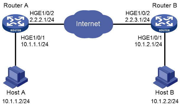
Network configuration
As shown in Figure 8, establish an IPsec tunnel between Router A and Router B to protect data flows between subnet 10.1.1.0/24 and subnet 10.1.2.0/24. Configure the tunnel as follows:
· Specify the encapsulation mode as tunnel, the security protocol as ESP, the encryption algorithm as 128-bit AES, and the authentication algorithm as HMAC-SHA1.
· Manually set up IPsec SAs.
Procedure
1. Configure Router A:
# Configure IP addresses for interfaces. (Details not shown.)
# Configure an IPv4 advanced ACL to identify data flows from subnet 10.1.1.0/24 to subnet 10.1.2.0/24.
<RouterA> system-view
[RouterA] acl advanced 3101
[RouterA-acl-ipv4-adv-3101] rule permit ip source 10.1.1.0 0.0.0.255 destination 10.1.2.0 0.0.0.255
[RouterA-acl-ipv4-adv-3101] quit
# Configure a static route to Host B. The command uses the direct next hop address (2.2.2.3) as an example.
[RouterA] ip route-static 10.1.2.0 255.255.255.0 hundredgige 1/0/2 2.2.2.3
# Create an IPsec transform set named tran1.
[RouterA] ipsec transform-set tran1
# Specify the tunnel encapsulation mode.
[RouterA-ipsec-transform-set-tran1] encapsulation-mode tunnel
# Specify the ESP security protocol.
[RouterA-ipsec-transform-set-tran1] protocol esp
# Specify the ESP encryption and authentication algorithms.
[RouterA-ipsec-transform-set-tran1] esp encryption-algorithm aes-cbc-128
[RouterA-ipsec-transform-set-tran1] esp authentication-algorithm sha1
[RouterA-ipsec-transform-set-tran1] quit
# Create an IKE-based IPsec policy entry with name map1 and sequence number 10.
[RouterA] ipsec policy map1 10 manual
# Apply ACL 3101.
[RouterA-ipsec-policy-manual-map1-10] security acl 3101
# Apply IPsec transform set tran1.
[RouterA-ipsec-policy-manual-map1-10] transform-set tran1
# Specify 2.2.3.1 as the remote IP address of the IPsec tunnel.
[RouterA-ipsec-policy-manual-map1-10] remote-address 2.2.3.1
# Configure the inbound and outbound SPIs for ESP.
[RouterA-ipsec-policy-manual-map1-10] sa spi outbound esp 12345
[RouterA-ipsec-policy-manual-map1-10] sa spi inbound esp 54321
# Configure the inbound and outbound SA keys for ESP.
[RouterA-ipsec-policy-manual-map1-10] sa string-key outbound esp simple abcdefg
[RouterA-ipsec-policy-manual-map1-10] sa string-key inbound esp simple gfedcba
[RouterA-ipsec-policy-manual-map1-10] quit
# Apply IPsec policy map1 to HundredGigE 1/0/2.
[RouterA] interface hundredgige 1/0/2
[RouterA-HundredGigE1/0/2] ip address 2.2.2.1 255.255.255.0
[RouterA-HundredGigE1/0/2] ipsec apply policy map1
[RouterA-HundredGigE1/0/2] quit
2. Configure Router B:
# Configure IP addresses for interfaces. (Details not shown.)
# Configure an IPv4 advanced ACL to identify data flows from subnet 10.1.2.0/24 to subnet 10.1.1.0/24.
<RouterB> system-view
[RouterB] acl advanced 3101
[RouterB-acl-ipv4-adv-3101] rule permit ip source 10.1.2.0 0.0.0.255 destination 10.1.1.0 0.0.0.255
[RouterB-acl-ipv4-adv-3101] quit
# Configure a static route to Host A. The command uses the direct next hop address (2.2.3.3) as an example.
[RouterB] ip route-static 10.1.1.0 255.255.255.0 hundredgige 1/0/2 2.2.3.3
# Create an IPsec transform set named tran1.
[RouterB] ipsec transform-set tran1
# Specify the tunnel encapsulation mode.
[RouterB-ipsec-transform-set-tran1] encapsulation-mode tunnel
# Specify the ESP security protocol.
[RouterB-ipsec-transform-set-tran1] protocol esp
# Specify the ESP encryption and authentication algorithms.
[RouterB-ipsec-transform-set-tran1] esp encryption-algorithm aes-cbc-128
[RouterB-ipsec-transform-set-tran1] esp authentication-algorithm sha1
[RouterB-ipsec-transform-set-tran1] quit
# Create a manual IPsec policy entry. Specify use1 as the policy name and set the sequence number to 10.
[RouterB] ipsec policy use1 10 manual
# Apply ACL 3101.
[RouterB-ipsec-policy-manual-use1-10] security acl 3101
# Apply IPsec transform set tran1.
[RouterB-ipsec-policy-manual-use1-10] transform-set tran1
# Specify 2.2.2.1 as the remote IP address for the IPsec tunnel.
[RouterB-ipsec-policy-manual-use1-10] remote-address 2.2.2.1
# Configure the inbound and outbound SPIs for ESP.
[RouterB-ipsec-policy-manual-use1-10] sa spi outbound esp 54321
[RouterB-ipsec-policy-manual-use1-10] sa spi inbound esp 12345
# Configure the inbound and outbound SA keys for ESP.
[RouterB-ipsec-policy-manual-use1-10] sa string-key outbound esp simple gfedcba
[RouterB-ipsec-policy-manual-use1-10] sa string-key inbound esp simple abcdefg
[RouterB-ipsec-policy-manual-use1-10] quit
# Apply IPsec policy use1 to HundredGigE 1/0/2.
[RouterB] interface hundredgige 1/0/2
[RouterB-HundredGigE1/0/2] ip address 2.2.3.1 255.255.255.0
[RouterB-HundredGigE1/0/2] ipsec policy use1
[RouterB-HundredGigE1/0/2] quit
Verifying the configuration
After the configuration is completed, an IPsec tunnel between Router A and Router B is established, and the traffic between subnet 10.1.1.0/24 and subnet 10.1.2.0/24 is IPsec-protected. This example uses Router A to verify the configuration.
# Display IPsec SAs on Router A.
[RouterA] display ipsec sa
-------------------------------
Interface: HundredGigE1/0/2
-------------------------------
-----------------------------
IPsec policy: map1
Sequence number: 10
Mode: Manual
-----------------------------
Tunnel id: 549
Encapsulation mode: tunnel
Path MTU: 1443
Tunnel:
local address: 2.2.2.1
remote address: 2.2.3.1
Flow:
as defined in ACL 3101
[Inbound ESP SA]
SPI: 54321 (0x0000d431)
Connection ID: 90194313219
Transform set: ESP-ENCRYPT-AES-CBC-128 ESP-AUTH-SHA1
No duration limit for this SA
[Outbound ESP SA]
SPI: 12345 (0x00003039)
Connection ID: 64424509441
Transform set: ESP-ENCRYPT-AES-CBC-128 ESP-AUTH-SHA1
No duration limit for this SA
Example: Configuring IPsec for RIPng
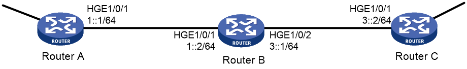
Network configuration
As shown in Figure 9, Router A, Router B, and Router C learn IPv6 routes through RIPng.
Establish an IPsec tunnel between the routers to protect the RIPng packets transmitted in between. Specify the security protocol as ESP, the encryption algorithm as 128-bit AES, and the authentication algorithm as HMAC-SHA1 for the IPsec tunnel.
Requirements analysis
To meet the network configuration requirements, perform the following tasks:
1. Configure basic RIPng.
For more information about RIPng configuration, see Layer 3—IP Routing Configuration Guide.
2. Configure an IPsec profile.
¡ The IPsec profiles on all the routers must have IPsec transform sets that use the same security protocol, authentication and encryption algorithms, and encapsulation mode.
¡ The SPI and key configured for the inbound SA and those for the outbound SA must be the same on each router.
¡ The SPI and key configured for the SAs on all the routers must be the same.
3. Apply the IPsec profile to a RIPng process or to an interface.
Procedure
1. Configure Router A:
# Configure IPv6 addresses for interfaces. (Details not shown.)
# Configure basic RIPng.
<RouterA> system-view
[RouterA] ripng 1
[RouterA-ripng-1] quit
[RouterA] interface hundredgige 1/0/1
[RouterA-HundredGigE1/0/1] ripng 1 enable
[RouterA-HundredGigE1/0/1] quit
# Create and configure the IPsec transform set named tran1.
[RouterA] ipsec transform-set tran1
[RouterA-ipsec-transform-set-tran1] encapsulation-mode transport
[RouterA-ipsec-transform-set-tran1] protocol esp
[RouterA-ipsec-transform-set-tran1] esp encryption-algorithm aes-cbc-128
[RouterA-ipsec-transform-set-tran1] esp authentication-algorithm sha1
[RouterA-ipsec-transform-set-tran1] quit
# Create and configure the IPsec profile named profile001.
[RouterA] ipsec profile profile001 manual
[RouterA-ipsec-profile-manual-profile001] transform-set tran1
[RouterA-ipsec-profile-manual-profile001] sa spi outbound esp 123456
[RouterA-ipsec-profile-manual-profile001] sa spi inbound esp 123456
[RouterA-ipsec-profile-manual-profile001] sa string-key outbound esp simple abcdefg
[RouterA-ipsec-profile-manual-profile001] sa string-key inbound esp simple abcdefg
[RouterA-ipsec-profile-manual-profile001] quit
# Apply the IPsec profile to RIPng process 1.
[RouterA] ripng 1
[RouterA-ripng-1] enable ipsec-profile profile001
[RouterA-ripng-1] quit
2. Configure Router B:
# Configure IPv6 addresses for interfaces. (Details not shown.)
# Configure basic RIPng.
<RouterB> system-view
[RouterB] ripng 1
[RouterB-ripng-1] quit
[RouterB] interface hundredgige 1/0/1
[RouterB-HundredGigE1/0/1] ripng 1 enable
[RouterB-HundredGigE1/0/1] quit
[RouterB] interface hundredgige 1/0/2
[RouterB-HundredGigE1/0/2] ripng 1 enable
[RouterB-HundredGigE1/0/2] quit
# Create and configure the IPsec transform set named tran1.
[RouterB] ipsec transform-set tran1
[RouterB-ipsec-transform-set-tran1] encapsulation-mode transport
[RouterB-ipsec-transform-set-tran1] protocol esp
[RouterB-ipsec-transform-set-tran1] esp encryption-algorithm aes-cbc-128
[RouterB-ipsec-transform-set-tran1] esp authentication-algorithm sha1
[RouterB-ipsec-transform-set-tran1] quit
# Create and configure the IPsec profile named profile001.
[RouterB] ipsec profile profile001 manual
[RouterB-ipsec-profile-manual-profile001] transform-set tran1
[RouterB-ipsec-profile-manual-profile001] sa spi outbound esp 123456
[RouterB-ipsec-profile-manual-profile001] sa spi inbound esp 123456
[RouterB-ipsec-profile-manual-profile001] sa string-key outbound esp simple abcdefg
[RouterB-ipsec-profile-manual-profile001] sa string-key inbound esp simple abcdefg
[RouterB-ipsec-profile-manual-profile001] quit
# Apply the IPsec profile to RIPng process 1.
[RouterB] ripng 1
[RouterB-ripng-1] enable ipsec-profile profile001
[RouterB-ripng-1] quit
3. Configure Router C:
# Configure IPv6 addresses for interfaces. (Details not shown.)
# Configure basic RIPng.
<RouterC> system-view
[RouterC] ripng 1
[RouterC-ripng-1] quit
[RouterC] interface hundredgige 1/0/1
[RouterC-HundredGigE1/0/1] ripng 1 enable
[RouterC-HundredGigE1/0/1] quit
# Create and configure the IPsec transform set named tran1.
[RouterC] ipsec transform-set tran1
[RouterC-ipsec-transform-set-tran1] encapsulation-mode transport
[RouterC-ipsec-transform-set-tran1] protocol esp
[RouterC-ipsec-transform-set-tran1] esp encryption-algorithm aes-cbc-128
[RouterC-ipsec-transform-set-tran1] esp authentication-algorithm sha1
[RouterC-ipsec-transform-set-tran1] quit
# Create and configure the IPsec profile named profile001.
[RouterC] ipsec profile profile001 manual
[RouterC-ipsec-profile-manual-profile001] transform-set tran1
[RouterC-ipsec-profile-manual-profile001] sa spi outbound esp 123456
[RouterC-ipsec-profile-manual-profile001] sa spi inbound esp 123456
[RouterC-ipsec-profile-manual-profile001] sa string-key outbound esp simple abcdefg
[RouterC-ipsec-profile-manual-profile001] sa string-key inbound esp simple abcdefg
[RouterC-ipsec-profile-manual-profile001] quit
# Apply the IPsec profile to RIPng process 1.
[RouterC] ripng 1
[RouterC-ripng-1] enable ipsec-profile profile001
[RouterC-ripng-1] quit
Verifying the configuration
After the configuration is completed, Router A, Router B, and Router C learn IPv6 routing information through RIPng. IPsec SAs are set up successfully on the routers to protect RIPng packets. This example uses Router A to verify the configuration.
# Display the RIPng configuration.
[RouterA] display ripng 1
RIPng process : 1
Preference : 100
Checkzero : Enabled
Default Cost : 0
Maximum number of load balanced routes : 8
Update time : 30 secs Timeout time : 180 secs
Suppress time : 120 secs Garbage-Collect time : 120 secs
Update output delay: 20(ms) Output count: 3
Graceful-restart interval: 60 secs
Triggered Interval : 5 50 200
Number of periodic updates sent : 186
Number of triggered updates sent : 1
IPsec profile name: profile001
The output shows that IPsec profile profile001 has been applied to RIPng process 1.
# Display the established IPsec SAs.
[RouterA] display ipsec sa
-------------------------------
Global IPsec SA
-------------------------------
-----------------------------
IPsec profile: profile001
Mode: Manual
-----------------------------
Encapsulation mode: transport
[Inbound ESP SA]
SPI: 123456 (0x3039)
Connection ID: 90194313219
Transform set: ESP-ENCRYPT-AES-CBC-128 ESP-AUTH-SHA1
No duration limit for this SA
[Outbound ESP SA]
SPI: 123456 (0x3039)
Connection ID: 64424509441
Transform set: ESP-ENCRYPT-AES-CBC-128 ESP-AUTH-SHA1
No duration limit for this SA
Example: Configuring IPsec RRI
Network configuration
As shown in Figure 10, branches access the enterprise center through an IPsec VPN.
Configure the IPsec VPN as follows:
· Configure an IPsec tunnel between Router A and each branch gateway (Router B, Router C, and Router D) to protect traffic between subnets 4.4.4.0/24 and 5.5.5.0/24.
· Configure the tunnels to use security protocol ESP, encryption algorithm DES, and authentication algorithm SHA1-HMAC-96. Use IKE for IPsec SA negotiation.
· On each router, configure an IKE proposal to use the preshared key authentication method, encryption algorithm 3DES, and authentication algorithm HMAC-SHA1.
· Configure IPsec RRI on Router A to automatically create static routes to the branches based on the established IPsec SAs.
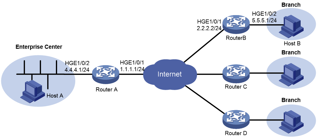
Procedure
1. Assign IPv4 addresses to the interfaces on the routers according to Figure 10. (Details not shown.)
2. Configure Router A:
# Create an IPsec transform set named tran1, and specify ESP as the security protocol, DES as the encryption algorithm, and HMAC-SHA-1-96 as the authentication algorithm.
<RouterA> system-view
[RouterA] ipsec transform-set tran1
[RouterA-ipsec-transform-set-tran1] encapsulation-mode tunnel
[RouterA-ipsec-transform-set-tran1] protocol esp
[RouterA-ipsec-transform-set-tran1] esp encryption-algorithm des
[RouterA-ipsec-transform-set-tran1] esp authentication-algorithm sha1
[RouterA-ipsec-transform-set-tran1] quit
# Create and configure the IPsec profile named profile1.
[RouterA] ike profile profile1
[RouterA-ike-profile-profile1] keychain key1
[RouterA-ike-profile-profile1] match remote identity address 2.2.2.2 255.255.255.0
[RouterA-ike-profile-profile1] quit
# Create an IPsec policy template named temp1. Specify IPsec transform set tran1 and IKE profile profile1 for the IPsec policy template.
[RouterA] ipsec policy-template temp1 1
[RouterA-ipsec-policy-template-temp1-1] transform-set tran1
[RouterA-ipsec-policy-template-temp1-1] ike-profile profile1
# Enable IPsec RRI, and set the preference to 100 and the tag to 1000 for the static routes created by IPsec RRI.
[RouterA-ipsec-policy-template-temp1-1] reverse-route dynamic
[RouterA-ipsec-policy-template-temp1-1] reverse-route preference 100
[RouterA-ipsec-policy-template-temp1-1] reverse-route tag 1000
[RouterA-ipsec-policy-template-temp1-1] quit
# Create an IKE-based IPsec policy entry with name map1 and sequence number 10.
[RouterA] ipsec policy map1 10 isakmp template temp1
# Create an IKE proposal named 1, and specify 3DES as the encryption algorithm, HMAC-SHA1 as the authentication algorithm, and pre-share as the authentication method.
[RouterA] ike proposal 1
[RouterA-ike-proposal-1] encryption-algorithm 3des-cbc
[RouterA-ike-proposal-1] authentication-algorithm sha
[RouterA-ike-proposal-1] authentication-method pre-share
[RouterA-ike-proposal-1] quit
# Create an IKE keychain named key1 and specify 123 in plain text as the preshared key to be used with the remote peer at 2.2.2.2.
[RouterA] ike keychain key1
[RouterA-ike-keychain-key1] pre-shared-key address 2.2.2.2 key simple 123
[RouterA-ike-keychain-key1] quit
# Apply IPsec policy map1 to HundredGigE 1/0/1.
[RouterA] interface hundredgige 1/0/1
[RouterA-HundredGigE1/0/1] ipsec apply policy map1
[RouterA-HundredGigE1/0/1] quit
3. Configure Router B:
# Create an IPsec transform set named tran1, and specify ESP as the security protocol, DES as the encryption algorithm, and HMAC-SHA-1-96 as the authentication algorithm.
[RouterB] ipsec transform-set tran1
[RouterB-ipsec-transform-set-tran1] encapsulation-mode tunnel
[RouterB-ipsec-transform-set-tran1] protocol esp
[RouterB-ipsec-transform-set-tran1] esp encryption-algorithm des
[RouterB-ipsec-transform-set-tran1] esp authentication-algorithm sha1
[RouterB-ipsec-transform-set-tran1] quit
# Configure IPv4 advanced ACL 3000 to identify traffic from subnet 5.5.5.0/24 to subnet 4.4.4.0/24.
[RouterB] acl advanced 3000
[RouterB-acl-ipv4-adv-3000] rule permit ip source 5.5.5.0 0.0.0.255 destination 4.4.4.0 0.0.0.255
[RouterB-acl-ipv4-adv-3000] quit
# Create and configure an IKE profile named profile1.
[RouterB] ike profile profile1
[RouterB-ike-profile-profile1] keychain key1
[RouterB-ike-profile-profile1] match remote identity address 1.1.1.1 255.255.255.0
[RouterB-ike-profile-profile1] quit
# Create an IKE-based IPsec policy entry named map1 and configure the following settings for the policy entry:
¡ Set the sequence number to 10.
¡ Specify transform set tran1 and ACL 3000.
¡ Specify the remote IP address for the tunnel as 1.1.1.1.
¡ Specify IKE profile profile1.
[RouterB] ipsec policy map1 10 isakmp
[RouterB-ipsec-policy-isakmp-map1-10] transform-set tran1
[RouterB-ipsec-policy-isakmp-map1-10] security acl 3000
[RouterB-ipsec-policy-isakmp-map1-10] remote-address 1.1.1.1
[RouterB-ipsec-policy-isakmp-map1-10] ike-profile profile1
[RouterB-ipsec-policy-isakmp-map1-10] quit
# Create an IKE proposal named 1, and specify 3DES as the encryption algorithm, HMAC-SHA1 as the authentication algorithm, and pre-share as the authentication method.
[RouterB] ike proposal 1
[RouterB-ike-proposal-1] encryption-algorithm 3des-cbc
[RouterB-ike-proposal-1] authentication-algorithm sha
[RouterB-ike-proposal-1] authentication-method pre-share
[RouterB-ike-proposal-1] quit
# Create an IKE keychain named key1 and specify 123 in plain text as the preshared key to be used with the remote peer at 1.1.1.1.
[RouterB] ike keychain key1
[RouterB-ike-keychain-key1] pre-shared-key address 1.1.1.1 key simple 123
[RouterB-ike-keychain-key1] quit
# Apply IPsec policy map1 to HundredGigE 1/0/1.
[RouterB] interface hundredgige 1/0/1
[RouterB-HundredGigE1/0/1] ipsec apply policy map1
[RouterB-HundredGigE1/0/1] quit
Make sure Router B has a route to the peer private network, with the outgoing interface as HundredGigE 1/0/1.
4. Configure Router C and Router D in the same way Router B is configured.
Verifying the configuration
1. Verify that IPsec RRI can automatically create a static route from Router A to Router B:
# Initiate a connection from subnet 5.5.5.0/24 to subnet 4.4.4.0/24. IKE negotiation is triggered to establish IPsec SAs between Router A and Router B. (Details not shown.)
# Verify that IPsec SAs are established on Router A.
[RouterA] display ipsec sa
-------------------------------
Interface: HundredGigE1/0/1
-------------------------------
-----------------------------
IPsec policy: map1
Sequence number: 10
Mode: Template
-----------------------------
Tunnel id: 0
Encapsulation mode: tunnel
Perfect Forward Secrecy:
Inside VPN:
Extended Sequence Numbers enable: N
Traffic Flow Confidentiality enable: N
Path MTU: 1463
Tunnel:
local address: 1.1.1.1
remote address: 2.2.2.2
Flow:
sour addr: 4.4.4.0/255.255.255.0 port: 0 protocol: ip
dest addr: 5.5.5.0/255.255.255.0 port: 0 protocol: ip
[Inbound ESP SAs]
SPI: 1014286405 (0x3c74c845)
Connection ID: 90194313219
Transform set: ESP-ENCRYPT-DES-CBC ESP-AUTH-SHA1
SA duration (kilobytes/sec): 1843200/3600
SA remaining duration (kilobytes/sec): 1843199/3590
Max received sequence-number: 4
Anti-replay check enable: Y
Anti-replay window size: 64
Status: Active
[Outbound ESP SAs]
SPI: 4011716027 (0xef1dedbb)
Connection ID: 64424509441
Transform set: ESP-ENCRYPT-DES-CBC ESP-AUTH-SHA1
SA duration (kilobytes/sec): 1843200/3600
SA remaining duration (kilobytes/sec): 1843199/3590
Max sent sequence-number: 4
Status: Active
# Verify that IPsec RRI has created a static route to reach Router B.
[RouterA] display ip routing-table verbose
2. Verify that Router A can automatically create static routes to Router C and Router D in the same way that you verify the IPsec RRI feature by using Router A and Router B. (Details not shown.)