- Table of Contents
- Related Documents
-
| Title | Size | Download |
|---|---|---|
| 05-IKE configuration | 305.11 KB |
Relationship between IPsec and IKE
Prerequisites for IKE configuration
Configuring peer IDs for the IKE profile
Specifying the IKE keychain or PKI domain
Configuring the IKE phase 1 negotiation mode
Specifying IKE proposals for the IKE profile
Configuring the local ID for the IKE profile
Specifying an inside VPN instance for the IKE profile
Configuring optional features for the IKE profile
Configuring the global identity information
Configuring the IKE keepalive feature
Configuring the IKE NAT keepalive feature
Setting the maximum number of IKE SAs
Configuring an IKE IPv4 address pool
Configuring SNMP notifications and logging for IKE
Configuring SNMP notifications for IKE
Enabling logging for IKE negotiation
Example: Configuring main-mode IKE with preshared key authentication
Example: Configuring IKE remote extended authentication
Example: Configuring IKE local extended authentication and address pool authorization
Example: Configuring a gateway-to-gateway IPsec tunnel with IKE extended authentication
IKE negotiation failed because no matching IKE proposals were found
IKE negotiation failed because no IKE proposals or IKE keychains are specified correctly
IPsec SA negotiation failed because no matching IPsec transform sets were found
IPsec SA negotiation failed due to invalid identity information
Configuring IKE
Unless otherwise specified, the term "IKE" in this chapter refers to IKEv1.
About IKE
Built on a framework defined by ISAKMP, Internet Key Exchange (IKE) provides automatic key negotiation and SA establishment services for IPsec.
Benefits of IKE
IKE provides the following benefits for IPsec:
· Automatically negotiates IPsec parameters.
· Performs DH exchanges to calculate shared keys, making sure each SA has a key that is independent of other keys.
· Automatically negotiates SAs when the sequence number in the AH or ESP header overflows, making sure IPsec can provide the anti-replay service by using the sequence number.
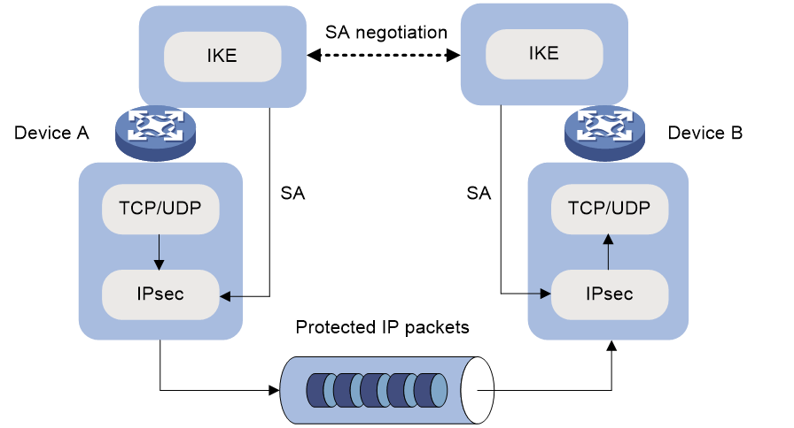
Relationship between IPsec and IKE
As shown in Figure 1, IKE negotiates SAs for IPsec and transfers the SAs to IPsec, and IPsec uses the SAs to protect IP packets.
Figure 1 Relationship between IKE and IPsec
IKE negotiation process
IKE negotiates keys and SAs for IPsec in two phases:
1. Phase 1—The two peers establish an IKE SA, a secure, authenticated channel for communication.
2. Phase 2—Using the IKE SA established in phase 1, the two peers negotiate to establish IPsec SAs.
Phase 1 negotiation can use the main mode or aggressive mode.
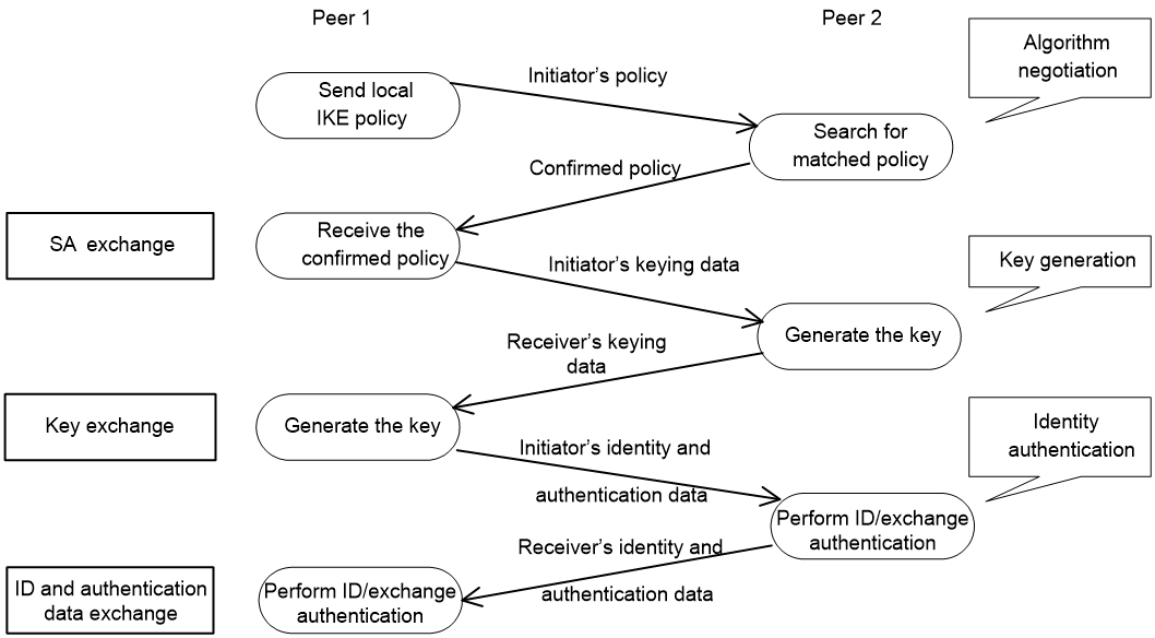
IKE exchange process in main mode
As shown in Figure 2, the main mode of IKE negotiation in phase 1 involves three pairs of messages:
· SA exchange—Used for negotiating the IKE security policy.
· Key exchange—Used for exchanging the DH public value and other values, such as the random number. The two peers use the exchanged data to generate key data and use the encryption key and authentication key to ensure the security of IP packets.
· ID and authentication data exchange—Used for identity authentication.
Figure 2 IKE exchange process in main mode
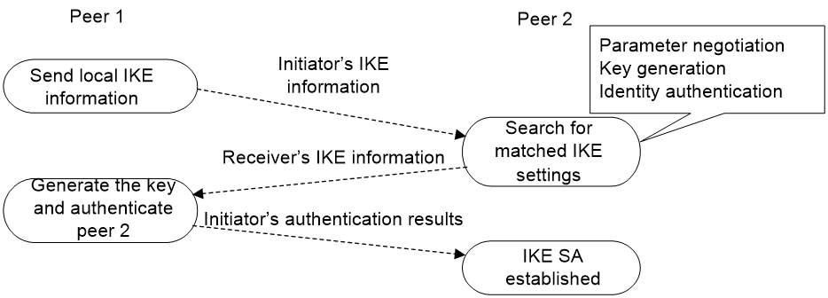
IKE exchange process in aggressive mode
As shown in Figure 3, the process of phase 1 IKE negotiation in aggressive mode is as follows:
1. The initiator (peer 1) sends a message containing the local IKE information to peer 2. The message includes parameters used for IKE SA establishment, keying data, and peer 1's identity information.
2. Peer 2 chooses the IKE establishment parameters to use, generate the key, and authenticate peer 1's identity. Then it sends the IKE data to peer 1.
3. Peer 1 generates the key, authenticates peer 2's identity, and sends the results to peer 1.
After the preceding process, an IKE SA is established between peer 1 and peer 2.
The aggressive mode is faster than the main mode but it does not provide identity information protection. The main mode provides identity information protection but is slower. Choose the appropriate negotiation mode according to your requirements.
Figure 3 IKE exchange process in aggressive mode
IKE security mechanism
IKE has a series of self-protection mechanisms and supports secure identity authentication, key distribution, and IPsec SA establishment on insecure networks.
Identity authentication
The IKE identity authentication mechanism is used to authenticate the identity of the communicating peers. The device supports the following identity authentication methods:
· Preshared key authentication—Two communicating peers use the pre-configured shared key for identity authentication.
· RSA signature authentication and DSA signature authentication—Two communicating peers use the digital certificates issued by the CA for identity authentication.
The preshared key authentication method does not require certificates and is easy to configure. It is usually deployed in small networks.
The signature authentication methods provide higher security and are usually deployed in networks with the headquarters and some branches. When deployed in a network with many branches, a signature authentication method can simplify the configuration because only one PKI domain is required. If you use the preshared key authentication method, you must configure a preshared key for each branch on the Headquarters node.
DH algorithm
The DH algorithm is a public key algorithm. With this algorithm, two peers can exchange keying material and then use the material to calculate the shared keys. Due to the decryption complexity, a third party cannot decrypt the keys even after intercepting all keying materials.
PFS
The Perfect Forward Secrecy (PFS) feature is a security feature based on the DH algorithm. After PFS is enabled, an additional DH exchange is performed in IKE phase 2 to make sure IPsec keys have no derivative relations with IKE keys and a broken key brings no threats to other keys.
Protocols and standards
· RFC 2408, Internet Security Association and Key Management Protocol (ISAKMP)
· RFC 2409, The Internet Key Exchange (IKE)
· RFC 2412, The OAKLEY Key Determination Protocol
· Internet Draft, draft-ietf-ipsec-isakmp-xauth-06
Internet Draft, draft-dukes-ike-mode-cfg-02
IKE tasks at a glance
To configure IKE, perform the following tasks:
1. (Optional.) Configuring an IKE profile
b. Configuring peer IDs for the IKE profile
c. Specifying the IKE keychain or PKI domain
d. Configuring the IKE phase 1 negotiation mode
e. Specifying IKE proposals for the IKE profile
f. Configuring the local ID for the IKE profile
g. Specifying an inside VPN instance for the IKE profile
h. Configuring optional features for the IKE profile
2. Configuring an IKE proposal
3. Configuring an IKE keychain
4. (Optional.) Configuring the global identity information
5. (Optional.) Configuring the IKE keepalive feature
6. (Optional.) Configuring the IKE NAT keepalive feature
7. (Optional.) Configuring global IKE DPD
8. (Optional.) Enabling invalid SPI recovery
9. (Optional.) Setting the maximum number of IKE SAs
10. (Optional.) Configuring an IKE IPv4 address pool
11. (Optional.) Configuring SNMP notifications and logging for IKE
Prerequisites for IKE configuration
Determine the following parameters prior to IKE configuration:
· The algorithms to be used during IKE negotiation, including the identity authentication method, encryption algorithm, authentication algorithm, and DH group.
¡ Different algorithms provide different levels of protection. A stronger algorithm provides more resistance to decryption but uses more resources.
¡ A DH group that uses more bits provides higher security but needs more time for processing.
· The preshared key or PKI domain for IKE negotiation. For more information about PKI, see Security Configuration Guide.
· The IKE-based IPsec policies for the communicating peers. If you do not specify an IKE profile in an IPsec policy, the device selects an IKE profile for the IPsec policy. If no IKE profile is configured, the globally configured IKE settings are used. For more information about IPsec, see "Configuring IPsec."
Configuring an IKE profile
Creating an IKE profile
About this task
Perform this task to create an IKE profile.
An IKE profile is intended to provide a set of parameters for IKE negotiation.
Procedure
1. Enter system view.
system-view
2. Create an IKE profile and enter its view.
ike profile profile-name
Configuring peer IDs for the IKE profile
About this task
Perform this task to configure the peer IDs for IKE profile matching. When the device needs to select an IKE profile for IKE negotiation with a peer, it compares the received peer ID with the peer IDs of its local IKE profiles. If a match is found, it uses the IKE profile with the matching peer ID for IKE negotiation.
Restrictions and guidelines
For an IKE profile, you can configure multiple peer IDs. A peer ID configured earlier has a higher priority.
Two IKE peers must both have or both not have peer IDs configured.
Procedure
1. Enter system view.
system-view
2. Enter IKE profile view.
ike profile profile-name
3. Configure a peer ID for the IKE profile.
match remote { certificate policy-name | identity { address { { ipv4-address [ mask | mask-length ] | range low-ipv4-address high-ipv4-address } | ipv6 { ipv6-address [ prefix-length ] | range low-ipv6-address high-ipv6-address } } [ vpn-instance vpn-instance-name ] | fqdn fqdn-name | user-fqdn user-fqdn-name } }
Specifying the IKE keychain or PKI domain
Restrictions and guidelines
Configure the IKE keychain or PKI domain for the IKE proposals to use. To use digital signature authentication, configure a PKI domain. To use preshared key authentication, configure an IKE keychain.
Procedure
1. Enter system view.
system-view
2. Enter IKE profile view.
ike profile profile-name
3. Specify the keychain for preshared key authentication or the PKI domain used to request a certificate for digital signature authentication.
¡ Specify the keychain.
keychain keychain-name
¡ Specify the PKI domain.
certificate domain domain-name
By default, no IKE keychain or PKI domain is specified in an IKE profile.
Configuring the IKE phase 1 negotiation mode
Restrictions and guidelines
Specify the IKE phase 1 negotiation mode (main or aggressive) that the device uses as the initiator. When the device acts as the responder, it uses the IKE negotiation mode of the initiator.
Procedure
1. Enter system view.
system-view
2. Enter IKE profile view.
ike profile profile-name
3. Specify the IKE negotiation mode for phase 1.
exchange-mode { aggressive | main }
By default, IKE negotiation in phase 1 uses the main mode.
Specifying IKE proposals for the IKE profile
Restrictions and guidelines
Specify the IKE proposals that the device can use as the initiator. An IKE proposal specified earlier has a higher priority. When the device acts as the responder, it uses the IKE proposals configured in system view to match the IKE proposals received from the initiator. If no matching proposal is found, the negotiation fails.
Procedure
1. Enter system view.
system-view
2. Enter IKE profile view.
ike profile profile-name
3. Specify IKE proposals for the IKE profile.
proposal proposal-number&<1-6>
By default, no IKE proposals are specified for an IKE profile and the IKE proposals configured in system view are used for IKE negotiation.
Configuring the local ID for the IKE profile
Restrictions and guidelines
For digital signature authentication, the device can use an ID of any type. If the local ID is an IP address that is different from the IP address in the local certificate, the device uses the FQDN (the device name configured by using the sysname command) instead.
For preshared key authentication, the device can use an ID of any type other than the DN.
Procedure
1. Enter system view.
system-view
2. Enter IKE profile view.
ike profile profile-name
3. Configure the local ID.
local-identity { address { ipv4-address | ipv6 ipv6-address } | dn | fqdn [ fqdn-name ] | user-fqdn [ user-fqdn-name ] }
By default, no local ID is configured for an IKE profile, and an IKE profile uses the local ID configured in system view. If the local ID is not configured in system view, the IKE profile uses the IP address of the interface to which the IPsec policy or IPsec policy template is applied as the local ID.
Specifying an inside VPN instance for the IKE profile
About this task
The inside MPLS L3VPN instance determines where the device should forward received IPsec protected data. If you specify an inside VPN instance, the device looks for a route in the specified VPN instance to forward the data. If you do not specify an inside VPN instance, the device looks for a route in the VPN instance where the receiving interface resides to forward the data.
Procedure
1. Enter system view.
system-view
2. Enter IKE profile view.
ike profile profile-name
3. Specify an inside VPN instance.
inside-vpn vpn-instance vpn-instance-name
By default, no inside VPN instance is specified for an IKE profile, and the device forwards protected data to the VPN instance where the interface receiving the data resides.
Configuring optional features for the IKE profile
1. Enter system view.
system-view
2. Enter IKE profile view.
ike profile profile-name
3. Configure optional features as needed.
¡ Configure IKE DPD.
dpd interval interval [ retry seconds ] { on-demand | periodic }
By default, IKE DPD is not configured for an IKE profile and an IKE profile uses the DPD settings configured in system view. If IKE DPD is not configured in system view either, the device does not perform dead IKE peer detection.
The IKE DPD settings configured in the IKE profile view take precedence over those configured in system view.
¡ Specify the local interface or IP address to which the IKE profile can be applied.
match local address { interface-type interface-number | { ipv4-address | ipv6 ipv6-address } [ vpn-instance vpn-instance-name ] }
By default, an IKE profile can be applied to any local interface or IP address.
An IKE profile configured with this command has a higher priority over those not configured with this command.
¡ Specify a priority for the IKE profile.
priority priority
By default, the priority of an IKE profile is 100.
The device selects a local IKE profile for IKE negotiation as follows:
- First, it selects an IKE profile with the match local address command configured.
- If a tie exists, it selects the IKE profile with a smaller priority number.
- If a tie still exists, it selects the IKE profile configured earlier.
¡ Enable client authentication.
client-authentication xauth
By default, client authentication is disabled.
Configure this command in the IKE profile used by the IPsec gateway at the enterprise center. This command enables the IPsec gateway to perform extended (XAUTH) authentication on remote users through AAA after IKE phase 1 negotiation. AAA configuration is also required on the IPsec gateway for client authentication.
¡ Specify the username and password for client authentication.
client-authentication xauth user
By default, the username and password for client authentication are not specified.
Configure this command in the IKE profile used by a branch gateway. The branch gateway can then use the username and password to pass AAA authentication and establish an IPsec tunnel with the IPsec gateway at the enterprise center.
¡ Enable AAA authorization.
aaa authorization domain domain-name username user-name
By default, AAA authorization is disabled.
The AAA authorization feature enables IKE to request authorization attributes, such as the IKE IPv4 address pool, from AAA. IKE uses the address pool to assign IPv4 addresses to remote users. For more information about AAA authorization, see AAA in User Access and Authentication Configuration Guide.
¡ (Optional.) Set the IKE SA soft lifetime buffer time.
sa soft-duration buffer seconds
By default, the IKE SA soft lifetime buffer time is not configured.
Set the IKE SA soft lifetime buffer time to determine the IKE SA soft lifetime. The SA soft lifetime is calculated as follows: SA soft lifetime = SA lifetime – SA soft lifetime buffer. A new IKE SA will be negotiated when the SA soft lifetime timer expires.
Configuring an IKE proposal
About this task
An IKE proposal defines a set of attributes describing how IKE negotiation in phase 1 should take place. You can create multiple IKE proposals with different priorities. The priority of an IKE proposal is represented by its sequence number. The lower the sequence number, the higher the priority.
Two peers must have at least one matching IKE proposal for successful IKE negotiation. During IKE negotiation:
· The initiator sends its IKE proposals to the peer.
¡ If the initiator is using an IPsec policy with an IKE profile, the initiator sends all IKE proposals specified in the IKE profile to the peer. An IKE proposal specified earlier for the IKE profile has a higher priority.
¡ If the initiator is using an IPsec policy with no IKE profile, the initiator sends all its IKE proposals to the peer. An IKE proposal with a smaller number has a higher priority.
· The peer searches its own IKE proposals for a match. The search starts from the IKE proposal with the highest priority and proceeds in descending order of priority until a match is found. The matching IKE proposals are used to establish the IKE SA. If all user-defined IKE proposals are found mismatching, the two peers use their default IKE proposals to establish the IKE SA.
Two matching IKE proposals have the same encryption algorithm, authentication method, authentication algorithm, and DH group. The SA lifetime takes the smaller one of the two proposals' SA lifetime settings.
Procedure
1. Enter system view.
system-view
2. Create an IKE proposal and enter its view.
ike proposal proposal-number
By default, a default IKE proposal exists.
3. Configure a description for the IKE proposal.
description
By default, an IKE proposal does not have a description.
4. Specify an encryption algorithm for the IKE proposal.
encryption-algorithm { 3des-cbc | aes-cbc-128 | aes-cbc-192 | aes-cbc-256 | des-cbc }
By default, the 56-bit DES encryption algorithm in CBC mode is used.
5. Specify an authentication method for the IKE proposal.
authentication-method { dsa-signature | pre-share | rsa-signature }
By default, the preshared key authentication method is used.
6. Specify an authentication algorithm for the IKE proposal.
authentication-algorithm { md5 | sha | sha256 | sha384 | sha512 }
By default, the HMAC-SHA1 authentication algorithm is used.
7. Specify a DH group for key negotiation in phase 1.
dh { group1 | group14 | group2 | group24 | group5 }
DH group 1 (the 768-bit DH group) is used by default.
8. (Optional.) Set the IKE SA lifetime for the IKE proposal.
sa duration seconds
By default, the IKE SA lifetime is 86400 seconds.
If the IPsec SA lifetime is also configured, set the IKE SA lifetime longer than the IPsec SA lifetime as a best practice.
Configuring an IKE keychain
About this task
Perform this task when you configure the IKE to use the preshared key for authentication.
Follow these guidelines when you configure an IKE keychain:
· Two peers must be configured with the same preshared key to pass preshared key authentication.
· You can specify the local address configured in IPsec policy or IPsec policy template view (using the local-address command) for the IKE keychain to be applied. If no local address is configured, specify the IP address of the interface that uses the IPsec policy.
· The device determines the priority of an IKE keychain as follows:
a. The device examines the existence of the match local address command. An IKE keychain with the match local address command configured has a higher priority.
b. If a tie exists, the device compares the priority numbers. An IKE keychain with a smaller priority number has a higher priority.
c. If a tie still exists, the device prefers an IKE keychain configured earlier.
Procedure
1. Enter system view.
system-view
2. Create an IKE keychain and enter its view.
ike keychain keychain-name [ vpn-instance vpn-instance-name ]
3. Configure a preshared key.
pre-shared-key { address { ipv4-address [ mask | mask-length ] | ipv6 ipv6-address [ prefix-length ] } | hostname host-name } key { cipher | simple } string
By default, no preshared key is configured.
4. (Optional.) Specify a local interface or IP address to which the IKE keychain can be applied.
match local address { interface-type interface-number | { ipv4-address | ipv6 ipv6-address } [ vpn-instance vpn-instance-name ] }
By default, an IKE keychain can be applied to any local interface or IP address.
5. (Optional.) Specify a priority for the IKE keychain.
priority priority
The default priority is 100.
Configuring the global identity information
Restrictions and guidelines
The global identity can be used by the device for all IKE SA negotiations, and the local identity (set by the local-identity command) can be used only by the device that uses the IKE profile.
When signature authentication is used, you can set any type of the identity information.
When preshared key authentication is used, you cannot set the DN as the identity.
Procedure
1. Enter system view.
system-view
2. Configure the global identity to be used by the local end.
ike identity { address { ipv4-address | ipv6 ipv6-address }| dn | fqdn [ fqdn-name ] | user-fqdn [ user-fqdn-name ] }
By default, the IP address of the interface to which the IPsec policy or IPsec policy template is applied is used as the IKE identity.
3. (Optional.) Configure the local device to always obtain the identity information from the local certificate for signature authentication.
ike signature-identity from-certificate
By default, the local end uses the identity information specified by local-identity or ike identity for signature authentication.
Configure this command when the aggressive mode and signature authentication are used and the device interconnects with a Comware 5-based peer device. Comware 5 supports only DN for signature authentication.
Configuring the IKE keepalive feature
About this task
IKE sends keepalive packets to query the liveness of the peer. If the peer is configured with the keepalive timeout time, you must configure the keepalive interval on the local device. If the peer receives no keepalive packets during the timeout time, the IKE SA is deleted along with the IPsec SAs it negotiated.
Restrictions and guidelines
Configure IKE DPD instead of IKE keepalive unless IKE DPD is not supported on the peer. The IKE keepalive feature sends keepalives at regular intervals, which consumes network bandwidth and resources.
The keepalive timeout time configured on the local device must be longer than the keepalive interval configured at the peer. Since it seldom occurs that more than three consecutive packets are lost on a network, you can set the keepalive timeout three times as long as the keepalive interval.
Procedure
1. Enter system view.
system-view
2. Set the IKE SA keepalive interval.
ike keepalive interval interval
By default, no keepalives are sent to the peer.
3. Set the IKE SA keepalive timeout time.
ike keepalive timeout seconds
By default, IKE SA keepalive never times out.
Configuring the IKE NAT keepalive feature
About this task
If IPsec traffic passes through a NAT device, you must configure the NAT traversal feature. If no packet travels across an IPsec tunnel in a period of time, the NAT sessions are aged and deleted, disabling the tunnel from transmitting data to the intended end. To prevent NAT sessions from being aged, configure the NAT keepalive feature on the IKE gateway behind the NAT device to send NAT keepalive packets to its peer periodically to keep the NAT session alive.
Procedure
1. Enter system view.
system-view
2. Set the IKE NAT keepalive interval.
ike nat-keepalive seconds
The default interval is 20 seconds.
Configuring global IKE DPD
About this task
DPD detects dead peers. It can operate in periodic mode or on-demand mode.
· Periodic DPD—Sends a DPD message at regular intervals. It features an earlier detection of dead peers, but consumes more bandwidth and CPU.
· On-demand DPD—Sends a DPD message based on traffic. When the device has traffic to send and is not aware of the liveness of the peer, it sends a DPD message to query the status of the peer. If the device has no traffic to send, it never sends DPD messages. As a best practice, use the on-demand mode.
The IKE DPD works as follows:
1. The local device sends a DPD message to the peer, and waits for a response from the peer.
2. If the peer does not respond within the retry interval specified by the retry seconds parameter, the local device resends the message.
3. If still no response is received within the retry interval, the local end sends the DPD message again. The system allows a maximum of four retries.
4. If the local device receives no response after four retries, the device considers the peer to be dead, and deletes the IKE SA along with the IPsec SAs it negotiated.
5. If the local device receives a response from the peer during the detection process, the peer is considered alive. The local device performs a DPD detection again when the triggering interval is reached or it has traffic to send, depending on the DPD mode.
Restrictions and guidelines
When DPD settings are configured in both IKE profile view and system view, the DPD settings in IKE profile view apply. If DPD is not configured in IKE profile view, the DPD settings in system view apply.
It is a good practice to set the triggering interval longer than the retry interval so that a DPD detection is not triggered during a DPD retry.
Procedure
1. Enter system view.
system-view
2. Enable sending IKE DPD messages.
ike dpd interval interval [ retry seconds ] { on-demand | periodic }
By default, IKE DPD is disabled.
Enabling invalid SPI recovery
About this task
An IPsec "black hole" occurs when one IPsec peer fails (for example, a peer can fail if a reboot occurs). One peer fails and loses its SAs with the other peer. When an IPsec peer receives a data packet for which it cannot find an SA, an invalid SPI is encountered. The peer drops the data packet and tries to send an SPI invalid notification to the data originator. This notification is sent by using the IKE SA. Because no IKE SA is available, the notification is not sent. The originating peer continues sending the data by using the IPsec SA that has the invalid SPI, and the receiving peer keeps dropping the traffic.
The invalid SPI recovery feature enables the receiving peer to set up an IKE SA with the originator so that an SPI invalid notification can be sent. Upon receiving the notification, the originating peer deletes the IPsec SA that has the invalid SPI. If the originator has data to send, new SAs will be set up.
Restrictions and guidelines
Use caution when you enable the invalid SPI recovery feature because using this feature can result in a DoS attack. Attackers can make a great number of invalid SPI notifications to the same peer.
Procedure
1. Enter system view.
system-view
2. Enable invalid SPI recovery.
ike invalid-spi-recovery enable
By default, the invalid SPI recovery is disabled.
Setting the maximum number of IKE SAs
About this task
You can set the maximum number of half-open IKE SAs and the maximum number of established IKE SAs.
· The supported maximum number of half-open IKE SAs depends on the device's processing capability. Adjust the maximum number of half-open IKE SAs to make full use of the device's processing capability without affecting the IKE SA negotiation efficiency.
· The supported maximum number of established IKE SAs depends on the device's memory space. Adjust the maximum number of established IKE SAs to make full use of the device's memory space without affecting other applications in the system.
Procedure
1. Enter system view.
system-view
2. Set the maximum number of half-open IKE SAs and the maximum number of established IKE SAs.
ike limit { max-negotiating-sa negotiation-limit | max-sa sa-limit }
By default, there is no limit to the maximum number of IKE SAs.
Configuring an IKE IPv4 address pool
About this task
To perform centralized management on remote users, an IPsec gateway can use an IPv4 address pool to assign private IPv4 addresses to remote users.
You must use an IKE IPv4 address pool together with AAA authorization by specifying the IKE IPv4 address pool as an AAA authorization attribute. For more information about AAA, see User Access and Authentication Configuration Guide.
Procedure
1. Enter system view.
system-view
2. Configure an IKE IPv4 address pool.
ike address-group group-name start-ipv4-address end-ipv4-address [ mask | mask-length ]
Configuring SNMP notifications and logging for IKE
Configuring SNMP notifications for IKE
About this task
After you enable SNMP notifications for IKE, the IKE module notifies the NMS of important module events. The notifications are sent to the device's SNMP module. For the notifications to be sent correctly, you must also configure SNMP on the device. For more information about SNMP notifications, see Network Management and Monitoring Configuration Guide.
To generate and output SNMP notifications for a specific IKE failure or event type, perform the following tasks:
1. Enable SNMP notifications for IKE globally.
2. Enable SNMP notifications for the failure or event type.
Procedure
1. Enter system view
system-view
2. Enable SNMP notifications for IKE globally.
snmp-agent trap enable ike global
By default, SNMP notifications for IKE are disabled.
3. Enable SNMP notifications for the specified failure or event types.
snmp-agent trap enable ike [ attr-not-support | auth-failure | cert-type-unsupport | cert-unavailable | decrypt-failure | encrypt-failure | invalid-cert-auth | invalid-cookie | invalid-id | invalid-proposal | invalid-protocol | invalid-sign | no-sa-failure | proposal-add | proposal–delete | tunnel-start | tunnel-stop | unsupport-exch-type ] *
By default, SNMP notifications for all failure and event types are disabled.
Enabling logging for IKE negotiation
About this task
This feature enables the device to output logs for the IKE negotiation process.
Procedure
1. Enter system view.
system-view
2. Enable logging for IKE negotiation.
ike logging negotiation enable
By default, logging for IKE negotiation is disabled.
Verifying and maintaining IKE
Displaying IKE information
Perform display tasks in any view.
· Display configuration information about all IKE proposals.
display ike proposal
· Display information about the current IKE SAs.
display ike sa [ verbose [ connection-id connection-id | remote-address [ ipv6 ] remote-address [ vpn-instance vpn-instance-name ] ] ]
· Display IKE statistics.
display ike statistics
Clearing IKE information
Perform clear tasks in user view.
· Delete IKE SAs.
reset ike sa [ connection-id connection-id ]
· Clear IKE MIB statistics.
reset ike statistics
IKE configuration examples
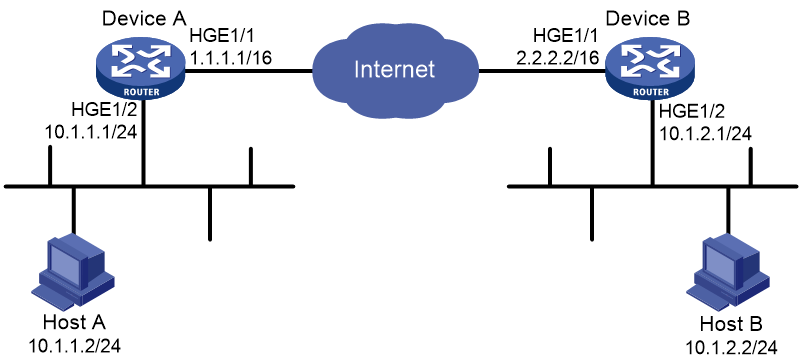
Example: Configuring main-mode IKE with preshared key authentication
Network configuration
As shown in Figure 4, configure an IKE-based IPsec tunnel between Device A and Device B to secure the communication between subnet 10.1.1.0/24 and subnet 10.1.2.0/24.
· Configure Device A and Device B to use the default IKE proposal for the IKE negotiation to set up the IPsec SAs.
· Configure the two devices to use the preshared key authentication method for the IKE negotiation phase 1.
Procedure
1. Configure Device A:
# Assign an IP address to each interface. (Details not shown.)
# Configure IPv4 advanced ACL 3101 to identify traffic from subnet 10.1.1.0/24 to subnet 10.1.2.0/24.
<DeviceA> system-view
[DeviceA] acl advanced 3101
[DeviceA-acl-ipv4-adv-3101] rule permit ip source 10.1.1.0 0.0.0.255 destination 10.1.2.0 0.0.0.255
[DeviceA-acl-ipv4-adv-3101] quit
# Create an IPsec transform set named tran1.
[DeviceA] ipsec transform-set tran1
# Set the packet encapsulation mode to tunnel.
[DeviceA-ipsec-transform-set-tran1] encapsulation-mode tunnel
# Use the ESP protocol for the IPsec transform set.
[DeviceA-ipsec-transform-set-tran1] protocol esp
# Specify the encryption and authentication algorithms.
[DeviceA-ipsec-transform-set-tran1] esp encryption-algorithm aes-cbc-128
[DeviceA-ipsec-transform-set-tran1] esp authentication-algorithm sha1
[DeviceA-ipsec-transform-set-tran1] quit
# Create an IKE keychain named keychain1.
[DeviceA] ike keychain keychain1
# Specify 123456TESTplat&! in plain text as the preshared key to be used with the remote peer at 2.2.2.2.
[DeviceA-ike-keychain-keychain1] pre-shared-key address 2.2.2.2 255.255.0.0 key simple 123456TESTplat&!
[DeviceA-ike-keychain-keychain1] quit
# Create an IKE profile named profile1.
[DeviceA] ike profile profile1
# Specify IKE keychain keychain1.
[DeviceA-ike-profile-profile1] keychain keychain1
# Configure the local ID with the identity type as IP address and the value as 1.1.1.1.
[DeviceA-ike-profile-profile1] local-identity address 1.1.1.1
# Specify IP address 2.2.2.2 as the peer ID.
[DeviceA-ike-profile-profile1] match remote identity address 2.2.2.2 255.255.0.0
[DeviceA-ike-profile-profile1] quit
# Create an IKE-based IPsec policy entry with name map1 and sequence number 10.
[DeviceA] ipsec policy map1 10 isakmp
# Specify the remote IP address 2.2.2.2 for the IPsec tunnel.
[DeviceA-ipsec-policy-isakmp-map1-10] remote-address 2.2.2.2
# Specify ACL 3101 to identify the traffic to be protected.
[DeviceA-ipsec-policy-isakmp-map1-10] security acl 3101
# Specify IPsec transform set tran1 for the IPsec policy.
[DeviceA-ipsec-policy-isakmp-map1-10] transform-set tran1
# Specify IKE profile profile1 for the IPsec policy.
[DeviceA-ipsec-policy-isakmp-map1-10] ike-profile profile1
[DeviceA-ipsec-policy-isakmp-map1-10] quit
# Apply IPsec policy map1 to HundredGigE 1/0/1.
[DeviceA] interface hundredgige 1/0/1
[DeviceA-HundredGigE1/0/1] ipsec apply policy map1
[DeviceA-HundredGigE1/0/1] quit
# Configure a static route to the subnet where Host B resides. This example uses 1.1.1.2 as the next hop IP address.
[DeviceA] ip route-static 10.1.2.0 255.255.255.0 1.1.1.2
2. Configure Device B:
# Assign an IP address to each interface. (Details not shown.)
# Configure IPv4 advanced ACL 3101 to identify traffic from subnet 10.1.2.0/24 to subnet 10.1.1.0/24.
<DeviceB> system-view
[DeviceB] acl advanced 3101
[DeviceB-acl-ipv4-adv-3101] rule permit ip source 10.1.2.0 0.0.0.255 destination 10.1.1.0 0.0.0.255
[DeviceB-acl-ipv4-adv-3101] quit
# Create an IPsec transform set named tran1.
[DeviceB] ipsec transform-set tran1
# Set the packet encapsulation mode to tunnel.
[DeviceB-ipsec-transform-set-tran1] encapsulation-mode tunnel
# Use the ESP protocol for the IPsec transform set.
[DeviceB-ipsec-transform-set-tran1] protocol esp
# Specify the encryption and authentication algorithms.
[DeviceB-ipsec-transform-set-tran1] esp encryption-algorithm aes-cbc-128
[DeviceB-ipsec-transform-set-tran1] esp authentication-algorithm sha1
[DeviceB-ipsec-transform-set-tran1] quit
# Create an IKE keychain named keychain1.
[DeviceB]ike keychain keychain1
# Specify 123456TESTplat&! in plain text as the preshared key to be used with the remote peer at 1.1.1.1.
[DeviceB-ike-keychain-keychain1] pre-shared-key address 1.1.1.1 255.255.0.0 key simple 123456TESTplat&!
[DeviceB-ike-keychain-keychain1] quit
# Create an IKE profile named profile1.
[DeviceB] ike profile profile1
# Specify IKE keychain keychain1
[DeviceB-ike-profile-profile1] keychain keychain1
# Configure the local ID with the identity type as IP address and the value as 2.2.2.2.
[DeviceB-ike-profile-profile1] local-identity address 2.2.2.2
# Configure a peer ID with the identity type as IP address and the value as 1.1.1.1/16.
[DeviceB-ike-profile-profile1] match remote identity address 1.1.1.1 255.255.0.0
[DeviceB-ike-profile-profile1] quit
# Create an IKE-based IPsec policy entry. Specify use1 as the policy name and set the sequence number to 10.
[DeviceB] ipsec policy use1 10 isakmp
# Specify the remote IP address 1.1.1.1 for the IPsec tunnel.
[DeviceB-ipsec-policy-isakmp-use1-10] remote-address 1.1.1.1
# Specify ACL 3101 to identify the traffic to be protected.
[DeviceB-ipsec-policy-isakmp-use1-10] security acl 3101
# Specify IPsec transform set tran1 for the IPsec policy.
[DeviceB-ipsec-policy-isakmp-use1-10] transform-set tran1
# Specify IKE profile profile1 for the IPsec policy.
[DeviceB-ipsec-policy-isakmp-use1-10] ike-profile profile1
[DeviceB-ipsec-policy-isakmp-use1-10] quit
# Apply IPsec policy use1 to HundredGigE 1/0/1.
[DeviceB] interface hundredgige 1/0/1
[DeviceB-HundredGigE1/0/1] ipsec apply policy use1
# Configure a static route to the subnet where Host A resides. This example uses 2.2.2.1 as the next hop IP address.
[DeviceB] ip route-static 10.1.1.0 255.255.255.0 2.2.2.1
Verifying the configuration
# Initiate a connection from subnet 10.1.1.0/24 to subnet 10.1.2.0/24 to trigger IKE negotiation. After IPsec SAs are successfully negotiated by IKE, traffic between the two subnets is IPsec-protected.
# Display the IKE proposal configuration on Device A and Device B. Because no IKE proposal is configured, the command displays the default IKE proposal.
[DeviceA] display ike proposal
Priority Authentication Authentication Encryption Diffie-Hellman Duration
method algorithm algorithm group (seconds)
----------------------------------------------------------------------------
default PRE-SHARED-KEY SHA1 DES-CBC Group 1 86400
[DeviceB] display ike proposal
Priority Authentication Authentication Encryption Diffie-Hellman Duration
method algorithm algorithm group (seconds)
----------------------------------------------------------------------------
default PRE-SHARED-KEY SHA1 DES-CBC Group 1 86400
# Display the IKE SA on Device A.
[DeviceA] display ike sa
Connection-ID Remote Flag DOI
------------------------------------------------------------------
1 2.2.2.2 RD IPsec
Flags:
RD--READY RL--REPLACED FD-FADING RK-REKEY
# Display the IPsec SAs generated on Device A.
[DeviceA] display ipsec sa
-------------------------------
Interface: HundredGigE1/0/1
-------------------------------
-----------------------------
IPsec policy: map1
Sequence number: 10
Mode: ISAKMP
-----------------------------
Tunnel id: 0
Encapsulation mode: tunnel
Perfect Forward Secrecy:
Inside VPN:
Extended Sequence Numbers enable: N
Traffic Flow Confidentiality enable: N
Path MTU: 1456
Tunnel:
local address: 1.1.1.1
remote address: 2.2.2.2
Flow:
sour addr: 10.1.1.0/255.255.255.0 port: 0 protocol: ip
dest addr: 10.1.2.0/255.255.255.0 port: 0 protocol: ip
[Inbound ESP SAs]
SPI: 3264152513 (0xc28f03c1)
Connection ID: 90194313219
Transform set: ESP-ENCRYPT-AES-CBC-128 ESP-AUTH-SHA1
SA duration (kilobytes/sec): 1843200/3600
SA remaining duration (kilobytes/sec): 1843200/3484
Max received sequence-number:
Anti-replay check enable: Y
Anti-replay window size: 64
UDP encapsulation used for NAT traversal: N
Status: Active
[Outbound ESP SAs]
SPI: 738451674 (0x2c03e0da)
Connection ID: 64424509441
Transform set: ESP-ENCRYPT-AES-CBC-128 ESP-AUTH-SHA1
SA duration (kilobytes/sec): 1843200/3600
SA remaining duration (kilobytes/sec): 1843200/3484
Max sent sequence-number:
UDP encapsulation used for NAT traversal: N
Status: Active
# Display the IKE SA and IPsec SAs on Device B.
[DeviceB] display ike sa
[DeviceB] display ipsec sa
Example: Configuring IKE remote extended authentication
Network configuration
As shown in Figure 5, configure an IPsec tunnel to protect the traffic between the host and the device.
· Set up IPsec SAs through IKE negotiations.
· Configure the host and the device to use preshared key for authentication in the phase-1 IKE negotiation.
· Configure the device to use RADIUS to perform remote extended authentication on the host.

Procedure
1. Make sure the device, host, and server can reach one another.
2. Configure the RADIUS server. Make sure the RADIUS server has an authentication account for the host. In this example, the account uses username test and password abc.
3. Configure the device:
# Configure IP addresses for interfaces. (Details not shown.)
# Create a RADIUS scheme named ike-scheme.
[Device] radius scheme ike-scheme
# Specify the IP address and service port of the primary RADIUS authentication server.
[Device-radius-ike-scheme] primary authentication 3.3.3.48 1645
# Set the shared key for secure RADIUS authentication communication.
[Device-radius-ike-scheme] key authentication simple abc
# Configure the device to send the username without the ISP domain name to the RADIUS server. (The configuration varies with the RADIUS server's requirements for username.)
[Device-radius-ike-scheme] user-name-format without-domain
[Device-radius-ike-scheme] quit
# Create an ISP domain named ike and specify the RADIUS scheme used for authenticating the IKE users.
[Device] domain ike
[Device-isp-ike] authentication ike radius-scheme ike-scheme
[Device-isp-ike] quit
# Configure an IPv4 advanced ACL to identify the packets to be protected.
[Device] acl advanced 3101
[Device-acl-ipv4-adv-3101] rule permit ip source 2.2.2.2 0.0.0.0 destination 1.1.1.1 0.0.0.0
[Device-acl-ipv4-adv-3101] quit
# Created an IPsec transform set named tran1.
[Device] ipsec transform-set tran1
# Specify the transport encapsulation mode.
[Device-ipsec-transform-set-tran1] encapsulation-mode transport
# Specify the ESP security protocol.
[Device-ipsec-transform-set-tran1] protocol esp
# Specify the ESP authentication algorithm and encryption algorithm.
[Device-ipsec-transform-set-tran1] esp encryption-algorithm aes-cbc-128
[Device-ipsec-transform-set-tran1] esp authentication-algorithm sha1
[Device-ipsec-transform-set-tran1] quit
# Create an IKE keychain named keychain1.
[Device] ike keychain keychain1
# Set the preshared key used for IKE negotiation with the peer at 1.1.1.1.
[Device-ike-keychain-keychain1] pre-shared-key address 1.1.1.1 255.255.255.255 key simple 123456TESTplat&!
[Device-ike-keychain-keychain1] quit
# Create an IKE profile named profile1.
[Device] ike profile profile1
# Specify the IKE keychain for the IKE profile.
[Device-ike-profile-profile1] keychain keychain1
# Specify IP address 2.2.2.2 as the local ID.
[Device-ike-profile-profile1] local-identity address 2.2.2.2
# Configure the peer ID for IKE profile matching.
[Device-ike-profile-profile1] match remote identity address 1.1.1.1 255.255.255.255
[Device-ike-profile-profile1] quit
# Enable XAUTH authentication for clients.
[Device-ike-profile-profile1] client-authentication xauth
[Device-ike-profile-profile1] quit
# Create an IKE-based IPsec policy entry with name map1 and sequence number 10.
[Device] ipsec policy map1 10 isakmp
# Specify the remote IP address for the IPsec tunnel.
[Device-ipsec-policy-isakmp-map1-10] remote-address 1.1.1.1
# Specify the ACL.
[Device-ipsec-policy-isakmp-map1-10] security acl 3101
# Specify the IPsec transform set.
[Device-ipsec-policy-isakmp-map1-10] transform-set tran1
# Specify the IKE profile.
[Device-ipsec-policy-isakmp-map1-10] ike-profile profile1
[Device-ipsec-policy-isakmp-map1-10] quit
# Apply the IPsec policy to HundredGigE 1/0/1.
[Device] interface hundredgige 1/0/1
[Device-HundredGigE1/0/1] ipsec apply policy map1
[Device-HundredGigE1/0/1] quit
4. Configure the host:
Perform the following tasks on the host and make sure the configuration matches that on the device:
¡ Specify the IP address of the remote security gateway.
¡ Set the preshared key used for IKE negotiation.
¡ Configure the username and password for IKE extended authentication.
¡ Specify the security protocol, encryption algorithm, and authentication algorithm.
¡ Configure IKE negotiation parameters.
¡ Configure the local ID and remote ID.
(Details not shown.)
Verifying the configuration
# Initiate a connection from the host (1.1.1.1) to the device (2.2.2.2) to trigger IKE negotiation. (Details not shown.)
# On the device, verify that an IKE SA to the peer 1.1.1.1 is established and that extended authentication is enabled for remote users.
[Device] display ike sa verbose remote-address 1.1.1.1
-----------------------------------------------
Connection ID: 18
Outside VPN:
Inside VPN:
Profile: profile1
Transmitting entity: Initiator
Initiator cookie: 1bcf453f0a217259
Responder cookie: 5e32a74dfa66a0a4
-----------------------------------------------
Local IP: 2.2.2.2
Local ID type: IPV4_ADDR
Local ID: 2.2.2.2
Remote IP: 1.1.1.1
Remote ID type: IPV4_ADDR
Remote ID: 1.1.1.1
Authentication-method: PRE-SHARED-KEY
Authentication-algorithm: SHA1
Encryption-algorithm: DES-CBC
Life duration(sec): 86400
Remaining key duration(sec): 84565
Exchange-mode: Aggressive
Diffie-Hellman group: Group 1
NAT traversal: Detected
Extend authentication: Enabled
Assigned IP address:
Vendor ID index: 0xa1d
Vendor ID sequence number: 0x0
# On the host, enter the correct username and password for extended authentication. After the authentication succeeds, the IPsec tunnel will be established. (Details not shown.)
# Verify that IPsec SAs have been established on the device.
Example: Configuring IKE local extended authentication and address pool authorization
Network configuration
As shown in Figure 6, configure an IPsec tunnel to protect the traffic between the host and the server.
· Set up IPsec SAs through IKE negotiations.
· Configure the host and the device to use preshared key for authentication in the phase-1 IKE negotiation.
· Configure the device to use AAA to perform local extended authentication on the host and assign an IPv4 address to the host.

Procedure
1. Make sure the device and the host can reach each other.
2. Configure local users on the device. In this example, the authentication account uses username test and password 123456TESTplat&!.
3. Configure the device:
# Configure IP addresses for interfaces. (Details not shown.)
# Create an ISP domain named dm.
<Device> system-view
[Device] domain dm
# Configure the device to perform IKE local authentication.
[Device-isp-dm] authentication ike local
# Configure the device to perform IKE local authorization.
[Device-isp-dm] authorization ike local
[Device-isp-dm] quit
# Create an IKE IPv4 address pool named pool with an IPv4 address range of 20.1.1.1 to 20.1.1.20.
[Device] ike address-group pool 20.1.1.1 20.1.1.20
# Add a network user named ike.
[Device] local-user ike class network
# Authorize user ike to use the IKE service.
[Device-luser-network-ike] service-type ike
# Specify IPv4 address pool pool as the authorized IPv4 address pool for user ike.
[Device-luser-network-ike] authorization-attribute ip-pool pool
[Device-luser-network-ike] quit
# Add a network user named test.
[Device] local-user test class network
# Authorize user test to use the IKE service.
[Device-luser-network-test] service-type ike
# Configure a password for user test.
[Device-luser-network-test] password simple 123456TESTplat&!
[Device-luser-network-test] quit
# Create an IKE keychain named keychain1.
[Device] ike keychain keychain1
# Set the preshared key used for IKE negotiation with the remote peer at 1.1.1.1.
[Device-ike-keychain-keychain1] pre-shared-key address 1.1.1.1 255.255.255.255 key simple 123456TESTplat&!
[Device-ike-keychain-keychain1] quit
# Create an IKE profile named profile1.
[Device] ike profile profile1
# Specify IKE keychain keychain1 for IKE profile profile1.
[Device-ike-profile-profile1] keychain keychain1
# Specify IP address 2.2.2.2 as the local ID.
[Device-ike-profile-profile1] local-identity address 2.2.2.2
# Configure the peer ID for IKE profile matching.
[Device-ike-profile-profile1] match remote identity address 1.1.1.1 255.255.255.255
# Enable XAUTH authentication for clients.
[Device-ike-profile-profile1] client-authentication xauth
# Enable AAA authorization. Specify ISP domain dm and username ike.
[Device-ike-profile-profile1] aaa authorization domain dm username ike
[Device-ike-profile-profile1] quit
# Created an IPsec transform set named tran1.
[Device] ipsec transform-set tran1
# Specify the transport encapsulation mode.
[Device-ipsec-transform-set-tran1] encapsulation-mode transport
# Specify the ESP security protocol.
[Device-ipsec-transform-set-tran1] protocol esp
# Specify the ESP authentication algorithm and encryption algorithm.
[Device-ipsec-transform-set-tran1] esp encryption-algorithm aes-cbc-256
[Device-ipsec-transform-set-tran1] esp authentication-algorithm sha1
[Device-ipsec-transform-set-tran1] quit
# Create an IPsec policy template entry. Specify the template name as pt and set the sequence number to 1.
[Device] ipsec policy-template pt 1
# Specify IPsec transform set tran1.
[Device-ipsec-policy-template-pt-1] transform-set tran1
# Specify IKE profile profile1.
[Device-ipsec-policy-template-pt-1] ike-profile profile1
# Enable IPsec RRI.
[Device-ipsec-policy-template-pt-1] reverse-route dynamic
[Device-ipsec-policy-template-pt-1] quit
# Use IPsec policy template pt to create an IKE-based IPsec policy entry. Specify the policy name as map1 and set the sequence number to 1.
[Device] ipsec policy map1 1 isakmp template pt
# Apply the IPsec policy to HundredGigE 1/0/1.
[Device] interface hundredgige 1/0/1
[Device-HundredGigE1/0/1] ipsec apply policy map1
[Device-HundredGigE1/0/1] quit
4. Configure the host:
Perform the following tasks on the host and make sure the configuration matches that on the device:
¡ Specify the IP address of the remote security gateway.
¡ Set the preshared key used for IKE negotiation.
¡ Configure the username and password for IKE client authentication.
¡ Specify the security protocol, encryption algorithm, and authentication algorithm.
¡ Configure IKE negotiation parameters.
¡ Configure the local ID and remote ID.
(Details not shown.)
Verifying the configuration
# Initiate a connection from the host (1.1.1.1) to the server (3.3.3.50) to trigger IKE negotiation. (Details not shown.)
# On the device, verify that an IKE SA to the peer 1.1.1.1 is established and that client authentication is enabled.
[Device] display ike sa verbose remote-address 1.1.1.1
-----------------------------------------------
Connection ID: 18
Outside VPN:
Inside VPN:
Profile: profile1
Transmitting entity: Responder
Initiator cookie: 1bcf453f0a217259
Responder cookie: 5e32a74dfa66a0a4
-----------------------------------------------
Local IP: 2.2.2.2
Local ID type: IPV4_ADDR
Local ID: 2.2.2.2
Remote IP: 1.1.1.1
Remote ID type: IPV4_ADDR
Remote ID: 1.1.1.1
Authentication-method: PRE-SHARED-KEY
Authentication-algorithm: SHA1
Encryption-algorithm: 3DES-CBC
Life duration(sec): 86400
Remaining key duration(sec): 84565
Exchange-mode: Main
Diffie-Hellman group: Group 2
NAT traversal: Detected
Extend authentication: Enabled
Assigned IP address: 20.1.1.2
Vendor ID index: 0xa1d
Vendor ID sequence number: 0x0
# On the host, enter the correct username and password for client authentication. After the authentication succeeds, the IPsec tunnel will be established. (Details not shown.)
# Verify that IPsec SAs are established on the device.
<Device> display ipsec sa
-------------------------------
Interface: HundredGigE1/0/1
-------------------------------
-----------------------------
IPsec policy: map1
Sequence number: 1
Mode: Template
-----------------------------
Tunnel id: 2
Encapsulation mode: tunnel
Perfect Forward Secrecy:
Path MTU: 1427
Tunnel:
local address: 2.2.2.2
remote address: 1.1.1.1
Flow:
sour addr: 0.0.0.0/0.0.0.0 port: 0 protocol: ip
dest addr: 20.1.1.2/255.255.255.255 port: 0 protocol: ip
[Inbound ESP SAs]
SPI: 2374047012 (0x8d811524)
Transform set: ESP-ENCRYPT-AES-CBC-256 ESP-AUTH-SHA1
SA duration (kilobytes/sec): 1843200/3600
SA remaining duration (kilobytes/sec): 1843198/3259
Max received sequence-number: 24
Anti-replay check enable: Y
Anti-replay window size: 64
UDP encapsulation used for NAT traversal: N
Status: Active
[Outbound ESP SAs]
SPI: 146589619 (0x08bcc7b3)
Transform set: ESP-ENCRYPT-AES-CBC-256 ESP-AUTH-SHA1
SA duration (kilobytes/sec): 1843200/3600
SA remaining duration (kilobytes/sec): 1843200/3259
Max sent sequence-number: 0
UDP encapsulation used for NAT traversal: N
Status: Active
SA duration (kilobytes/sec): 1843200/3600
SA remaining duration (kilobytes/sec): 1839568/3164
Max sent sequence-number: 2793
UDP encapsulation used for NAT traversal: N
Status: Active
Example: Configuring a gateway-to-gateway IPsec tunnel with IKE extended authentication
Network configuration
As shown in Figure 7, establish an IPsec tunnel between Device A and Device B as follows:
· Configure Device A and Device B to set up IPsec SAs through IKE negotiation and specify the preshared key authentication method for the phase-1 IKE negotiation.
· Configure Device B to perform IKE extended authentication on Device A by using the RADIUS authentication method.
· Configure Device A to use username test and password 123456TESTplat&! for the RADIUS authentication.

Procedure
1. Make sure Device A, Device B, and the RADIUS server can reach one another.
2. Configure Device A:
# Configure IPv4 advanced ACL 3101 to identify the traffic from Device A to Device B.
[DeviceA] acl advanced 3101
[DeviceA-acl-ipv4-adv-3101] rule permit ip source 1.1.1.1 0.0.0.0 destination 2.2.2.2 0.0.0.0
[DeviceA-acl-ipv4-adv-3101] quit
# Create an IPsec transform set named tran1.
[DeviceA] ipsec transform-set tran1
# Specify the transport encapsulation mode.
[DeviceA -ipsec-transform-set-tran1] encapsulation-mode transport
# Use the ESP protocol for the IPsec transform set.
[DeviceA-ipsec-transform-set-tran1] protocol esp
# Specify the encryption algorithm and authentication algorithm for ESP.
[DeviceA-ipsec-transform-set-tran1] esp encryption-algorithm aes-cbc-128
[DeviceA-ipsec-transform-set-tran1] esp authentication-algorithm sha1
[DeviceA-ipsec-transform-set-tran1] quit
# Create an IKE keychain named keychain1.
[DeviceA] ike keychain keychain1
# Specify 123456TESTplat&! in plain text as the preshared key to be used with the peer at 2.2.2.2.
[DeviceA-ike-keychain-keychain1] pre-shared-key address 2.2.2.2 255.255.255.255 key simple 123456TESTplat&!
[DeviceA-ike-keychain-keychain1] quit
# Create an IKE profile named profile1.
[DeviceA] ike profile profile1
# Specify IKE keychain keychain1.
[DeviceA-ike-profile-profile1] keychain keychain1
# Specify IP address 1.1.1.1 as the local ID.
[DeviceA-ike-profile-profile1] local-identity address 1.1.1.1
# Specify IP address 2.2.2.2 as the peer ID.
[DeviceA-ike-profile-profile1] match remote identity address 2.2.2.2 255.255.255.255
# Specify username test and password abc for extended authentication.
[DeviceA-ike-profile-profile1] client-authentication xauth user test password simple abc
[DeviceA-ike-profile-profile1] quit
# Create an IKE-based IPsec policy entry named policy1 with sequence number 10.
[DeviceA] ipsec policy policy1 10 isakmp
# Specify 2.2.2.2 as the remote IP address for the IPsec tunnel.
[DeviceA-ipsec-policy-isakmp-policy1-10] remote-address 2.2.2.2
# Specify 1.1.1.1 as the local IP address for the IPsec tunnel.
[DeviceA-ipsec-policy-isakmp-policy1-10] local-address 1.1.1.1
# Specify ACL 3101 to identify the traffic to be protected.
[DeviceA-ipsec-policy-isakmp- policy1-10] security acl 3101
# Specify IPsec transform set tran1 for the IPsec policy.
[DeviceA-ipsec-policy-isakmp- policy1-10] transform-set tran1
# Specify IKE profile profile1 for the IPsec policy.
[DeviceA-ipsec-policy-isakmp- policy1-10] ike-profile profile1
[DeviceA-ipsec-policy-isakmp- policy1-10] quit
# Apply IPsec policy policy1 to HundredGigE 1/0/1.
[DeviceA] interface hundredgige 1/0/1
[DeviceA-HundredGigE1/0/1] ipsec apply policy policy1
[DeviceA-HundredGigE1/0/1] quit
3. Configure Device B:
# Configure IP addresses for the interfaces, as shown in Figure 7. (Details not shown.)
# Create a RADIUS scheme named ike-scheme.
[DeviceB] radius scheme ike-scheme
# Specify the IP address and service port of the primary RADIUS authentication server.
[DeviceB-radius-ike-scheme] primary authentication 3.3.3.48 1645
# Set the shared key for secure RADIUS authentication communication.
[DeviceB-radius-ike-scheme] key authentication simple abc
# Configure the device to send the username without the ISP domain name to the RADIUS server. (The configuration varies with the RADIUS server's requirements for username.)
[DeviceB-radius-ike-scheme] user-name-format without-domain
[DeviceB-radius-ike-scheme] quit
# Create an ISP domain named ike and specify the RADIUS scheme used for authenticating the IKE users.
[DeviceB] domain ike
[DeviceB-isp-ike] authentication ike radius-scheme ike-scheme
[DeviceB-isp-ike] quit
# Configure an IPv4 advanced ACL to identify the packets to be protected.
[DeviceB] acl advanced 3101
[DeviceB-acl-ipv4-adv-3101] rule permit ip source 2.2.2.2 0.0.0.0 destination 1.1.1.1 0.0.0.0
[DeviceB-acl-ipv4-adv-3101] quit
# Created an IPsec transform set named tran1.
[DeviceB] ipsec transform-set tran1
# Specify the transport encapsulation mode.
[DeviceB-ipsec-transform-set-tran1] encapsulation-mode transport
# Specify the ESP security protocol.
[DeviceB-ipsec-transform-set-tran1] protocol esp
# Specify the ESP encryption algorithm and authentication algorithm.
[DeviceB-ipsec-transform-set-tran1] esp encryption-algorithm aes-cbc-128
[DeviceB-ipsec-transform-set-tran1] esp authentication-algorithm sha1
[DeviceB-ipsec-transform-set-tran1] quit
# Create an IKE keychain named keychain1.
[DeviceB] ike keychain keychain1
# Set the preshared key used for IKE negotiation with the peer at 1.1.1.1.
[DeviceB-ike-keychain-keychain1] pre-shared-key address 1.1.1.1 255.255.255.255 key simple 123456TESTplat&!
[DeviceB-ike-keychain-keychain1] quit
# Create an IKE profile named profile1.
[DeviceB] ike profile profile1
# Specify the IKE keychain for the IKE profile.
[DeviceB-ike-profile-profile1] keychain keychain1
# Specify IP address 2.2.2.2 as the local ID.
[DeviceB-ike-profile-profile1] local-identity address 2.2.2.2
# Specify IP address 1.1.1.1 as the peer ID for IKE profile matching.
[DeviceB-ike-profile-profile1] match remote identity address 1.1.1.1 255.255.255.255
# Enable XAUTH authentication for clients.
[DeviceB-ike-profile-profile1] client-authentication xauth
[DeviceB-ike-profile-profile1] quit
# Create an IPsec policy template entry. Specify template1 as the template name and set the sequence number to 1.
[DeviceB] ipsec policy-template template1 10
# Specify the remote IP address for the IPsec tunnel.
[DeviceB-ipsec-policy-isakmp-template1-10] remote-address 1.1.1.1
# Specify ACL 3101.
[DeviceB-ipsec-policy-isakmp-template1-10] security acl 3101
# Specify the IPsec transform set.
[DeviceB-ipsec-policy-isakmp-template1-10] transform-set tran1
# Specify the IKE profile.
[DeviceB-ipsec-policy-isakmp-template1-10] ike-profile profile1
[Device-ipsec-policy-isakmp-template1-10] quit
# Use IPsec policy template template1 to create an IKE-based IPsec policy entry.
[DeviceB]ipsec policy policy1 10 isakmp template template1
# Apply the IPsec policy to HundredGigE 1/0/1.
[DeviceB] interface hundredgige 1/0/1
[DeviceB-HundredGigE1/0/1] ipsec apply policy policy1
[DeviceB-HundredGigE1/0/1] quit
Verifying the configuration
# Enable Device A to send packets to the server at 3.3.3.48 to trigger IKE negotiation. Device A will send the username and password to Device B for extended authentication. After Device A passes the extended authentication, it can establish an IPsec tunnel with Device B. (Details not shown.)
# On Device B, verify that an IKE SA to peer 1.1.1.1 is established and that client authentication is enabled.
[DeviceB] display ike sa verbose remote-address 1.1.1.1
-----------------------------------------------
Connection ID: 18
Outside VPN:
Inside VPN:
Profile: profile1
Transmitting entity: Responder
-----------------------------------------------
Local IP: 2.2.2.2
Local ID type: IPV4_ADDR
Local ID: 2.2.2.2
Remote IP: 1.1.1.1
Remote ID type: IPV4_ADDR
Remote ID: 1.1.1.1
Authentication-method: PRE-SHARED-KEY
Authentication-algorithm: SHA1
Encryption-algorithm: 3DES-CBC
Life duration(sec): 86400
Remaining key duration(sec): 84565
Exchange-mode: Main
Diffie-Hellman group: Group 2
NAT traversal: Detected
Extend authentication: Enabled
Assigned IP address:
# Verify that IPsec SAs are established between Device A and Device B.
<DeviceB> display ipsec sa
-------------------------------
Interface: HundredGigE1/0/1
-------------------------------
-----------------------------
IPsec policy: map1
Sequence number: 1
Mode: Template
-----------------------------
Tunnel id: 2
Encapsulation mode: tunnel
Perfect Forward Secrecy:
Path MTU: 1427
Tunnel:
local address: 2.2.2.2
remote address: 1.1.1.1
Flow:
sour addr: 0.0.0.0/0.0.0.0 port: 0 protocol: ip
dest addr: 20.1.1.2/255.255.255.255 port: 0 protocol: ip
[Inbound ESP SAs]
SPI: 2374047012 (0x8d811524)
Transform set: ESP-ENCRYPT-AES-CBC-256 ESP-AUTH-SHA1
SA duration (kilobytes/sec): 1843200/3600
SA remaining duration (kilobytes/sec): 1843198/3259
Max received sequence-number: 24
Anti-replay check enable: Y
Anti-replay window size: 64
UDP encapsulation used for NAT traversal: N
Status: Active
[Outbound ESP SAs]
SPI: 146589619 (0x08bcc7b3)
Transform set: ESP-ENCRYPT-AES-CBC-256 ESP-AUTH-SHA1
SA duration (kilobytes/sec): 1843200/3600
SA remaining duration (kilobytes/sec): 1843200/3259
Max sent sequence-number: 0
UDP encapsulation used for NAT traversal: N
Status: Active
SA duration (kilobytes/sec): 1843200/3600
SA remaining duration (kilobytes/sec): 1839568/3164
Max sent sequence-number: 2793
UDP encapsulation used for NAT traversal: N
Status: Active
Troubleshooting IKE
IKE negotiation failed because no matching IKE proposals were found
Symptom
1. The IKE SA is in Unknown state.
<Sysname> display ike sa
Connection-ID Remote Flag DOI
------------------------------------------------------------------
1 192.168.222.5 Unknown IPsec
Flags:
RD--READY RL--REPLACED FD-FADING RK-REKEY
2. When IKE event debugging and packet debugging are enabled, the following messages appear:
IKE event debugging message:
The attributes are unacceptable.
IKE packet debugging message:
Construct notification packet: NO_PROPOSAL_CHOSEN.
Analysis
Certain IKE proposal settings are incorrect.
Solution
1. Examine the IKE proposal configuration to see whether the two ends have matching IKE proposals.
2. Modify the IKE proposal configuration to make sure the two ends have matching IKE proposals.
3. If the problem persists, contact H3C Support.
IKE negotiation failed because no IKE proposals or IKE keychains are specified correctly
Symptom
1. The IKE SA is in Unknown state.
<Sysname> display ike sa
Connection-ID Remote Flag DOI
------------------------------------------------------------------
1 192.168.222.5 Unknown IPsec
Flags:
RD--READY RL--REPLACED FD-FADING RK-REKEY
2. The following IKE event debugging or packet debugging message appeared:
IKE event debugging message:
Notification PAYLOAD_MALFORMED is received.
IKE packet debugging message:
Construct notification packet: PAYLOAD_MALFORMED.
Analysis
· If the following debugging information appeared, the matched IKE profile is not using the matched IKE proposal:
Failed to find proposal 1 in profile profile1.
· If the following debugging information appeared, the matched IKE profile is not using the matched IKE keychain:
Failed to find keychain keychain1 in profile profile1.
Solution
1. Verify that the matched IKE proposal (IKE proposal 1 in this debugging message example) is specified for the IKE profile (IKE profile 1 in the example).
2. Verify that the matched IKE keychain (IKE keychain 1 in this debugging message example) is specified for the IKE profile (IKE profile 1 in the example).
3. If the problem persists, contact H3C Support.
IPsec SA negotiation failed because no matching IPsec transform sets were found
Symptom
1. The display ike sa command shows that the IKE SA negotiation succeeded and the IKE SA is in RD state, but the display ipsec sa command shows that the expected IPsec SA has not been negotiated yet.
2. The following IKE debugging message appeared:
The attributes are unacceptable.
Or:
Construct notification packet: NO_PROPOSAL_CHOSEN.
Analysis
Certain IPsec policy settings are incorrect.
Solution
1. Examine the IPsec configuration to see whether the two ends have matching IPsec transform sets.
2. Modify the IPsec configuration to make sure the two ends have matching IPsec transform sets.
3. If the problem persists, contact H3C Support.
IPsec SA negotiation failed due to invalid identity information
Symptom
1. The display ike sa command shows that the IKE SA negotiation succeeded and the IKE SA is in RD state, but the display ipsec sa command shows that the expected IPsec SA has not been negotiated yet.
2. The following IKE debugging message appeared:
Notification INVALID_ID_INFORMATION is received.
Or:
Failed to get IPsec policy when renegotiating IPsec SA. Delete IPsec SA.
Construct notification packet: INVALID_ID_INFORMATION.
Analysis
Certain IPsec policy settings of the responder are incorrect. Verify the settings as follows:
1. Verify that matching IKE profiles were found in IKE negotiation phase 1. If no matching IKE profiles were found and the IPsec policy is using an IKE profile, the IPsec SA negotiation fails.
# Identify whether matching IKE profiles were found in IKE negotiation phase 1. The following output shows that no matching IKE profile was found:
<Sysname> display ike sa verbose
-----------------------------------------------
Connection ID: 3
Outside VPN:
Inside VPN:
Profile:
Transmitting entity: Responder
Initiator cookie: 1bcf453f0a217259
Responder cookie: 5e32a74dfa66a0a4
-----------------------------------------------
Local IP: 192.168.222.5
Local ID type: IPV4_ADDR
Local ID: 192.168.222.5
Remote IP: 192.168.222.71
Remote ID type: IPV4_ADDR
Remote ID: 192.168.222.71
Authentication-method: PRE-SHARED-KEY
Authentication-algorithm: MD5
Encryption-algorithm: 3DES-CBC
Life duration(sec): 86400
Remaining key duration(sec): 85847
Exchange-mode: Main
Diffie-Hellman group: Group 1
NAT traversal: Not detected
Vendor ID index: 0xa1d
Vendor ID sequence number: 0x0
# Identify whether the IPsec policy is using an IKE profile. The following output shows that an IKE profile is used by the IPsec policy.
[Sysname] display ipsec policy
-------------------------------------------
IPsec Policy: policy1
Interface: HundredGigE1/0/1
-------------------------------------------
-----------------------------
Sequence number: 1
Mode: ISAKMP
-----------------------------
Description:
Security data flow: 3000
Selector mode: aggregation
Local address: 192.168.222.5
Remote address: 192.168.222.71
Transform set: transform1
IKE profile: profile1
SA trigger mode: Auto
SA duration(time based): 3600 seconds
SA duration(traffic based): 1843200 kilobytes
SA soft-duration buffer(time based): 1000 seconds
SA soft-duration buffer(traffic based): 43200 kilobytes
SA idle time: 100 seconds
2. Verify that the ACL specified for the IPsec policy is correctly configured. If the flow range defined by the responder's ACL is smaller than that defined by the initiator's ACL, IPsec proposal matching will fail.
For example, if the initiator's ACL defines a flow from one network segment to another but the responder's ACL defines a flow from one host to another host, IPsec proposal matching will fail.
# On the initiator:
[Sysname] display acl 3000
Advanced IPv4 ACL 3000, 1 rule,
ACL's step is 5
rule 0 permit ip source 192.168.222.0 0.0.0.255 destination 192.168.222.0 0.0.0.255
# On the responder:
[Sysname] display acl 3000
Advanced IPv4 ACL 3000, 1 rule,
ACL's step is 5
rule 0 permit ip source 192.168.222.71 0 destination 192.168.222.5 0
3. Verify that the IPsec policy has a remote address and an IPsec transform set configured and that the IPsec transform set has all necessary settings configured.
If, for example, the IPsec policy has no remote address configured, the IPsec SA negotiation will fail:
[Sysname] display ipsec policy
-------------------------------------------
IPsec Policy: policy1
Interface: HundredGigE1/0/1
-------------------------------------------
-----------------------------
Sequence number: 1
Mode: ISAKMP
-----------------------------
Security data flow: 3000
Selector mode: aggregation
Local address: 192.168.222.5
Remote address:
Transform set: transform1
IKE profile: profile1
SA trigger mode: Auto
SA duration(time based): 3600 seconds
SA duration(traffic based): 1843200 kilobytes
SA soft-duration buffer(time based): 1000 seconds
SA soft-duration buffer(traffic based): 43200 kilobytes
SA idle time: 100 seconds
Solution
1. If the IPsec policy specifies an IKE profile but no matching IKE profiles was found in IKE negotiation, perform one of the following tasks on the responder:
¡ Remove the specified IKE profile from the IPsec policy.
¡ Modify the specified IKE profile to match the IKE profile of the initiator.
2. If the flow range defined by the responder's ACL is smaller than that defined by the initiator's ACL, modify the responder's ACL so the ACL defines a flow range equal to or greater than that of the initiator's ACL.
For example:
[Sysname] display acl 3000
Advanced IPv4 ACL 3000, 2 rules,
ACL's step is 5
rule 0 permit ip source 192.168.222.0 0.0.0.255 destination 192.168.222.0 0.0.0.255
3. Configure the missing settings (for example, the remote address).
4. If the problem persists, contact H3C Support.