- Table of Contents
- Related Documents
-
| Title | Size | Download |
|---|---|---|
| 01-IPv4 over IPv4 tunneling configuration | 93.81 KB |
About IPv4 over IPv4 tunneling
Restrictions and guidelines: IPv4 over IPv4 tunnel configuration
Configuring an IPv4 over IPv4 tunnel
Verifying and maintaining IPv4 over IPv4 tunneling
Displaying IPv4 over IPv4 tunnel interface information
Clearing IPv4 over IPv4 tunnel interface statistics
IPv4 over IPv4 tunneling
About IPv4 over IPv4 tunneling
IPv4 over IPv4 tunneling (RFC 1853) enables isolated IPv4 networks to communicate. For example, an IPv4 over IPv4 tunnel can connect isolated private IPv4 networks over a public IPv4 network.
Figure 1 IPv4 over IPv4 tunnel
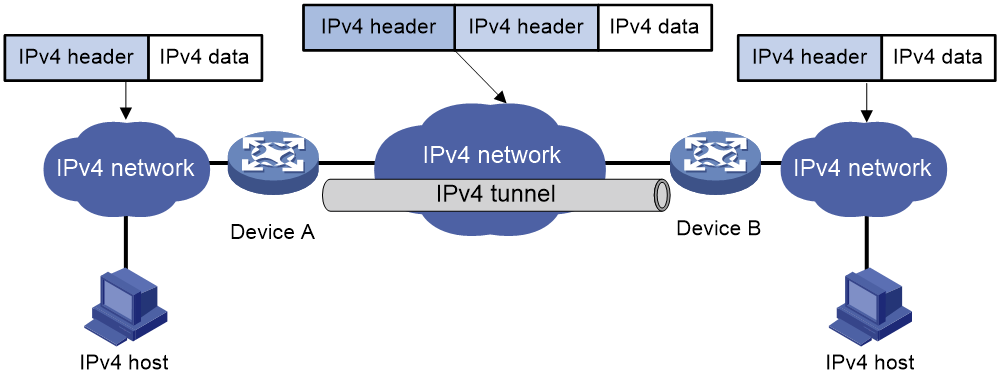
Figure 1 shows the encapsulation and de-encapsulation processes.
· Encapsulation:
a. Device A receives an IP packet from an IPv4 host and submits it to the IP protocol stack.
b. The IPv4 protocol stack determines how to forward the packet according to the destination address in the IP header. If the packet is destined for the IPv4 host connected to Device B, Device A delivers the packet to the tunnel interface.
c. The tunnel interface adds a new IPv4 header to the IPv4 packet and submits it to the IP protocol stack.
In the new header, the source IP address specifies the tunnel source, and the destination IP address specifies the tunnel destination.
d. The IP protocol stack uses the destination IP address of the new IP header to look up the routing table, and then sends the packet out.
· De-encapsulation:
a. After receiving the packet, Device B delivers it to the IP protocol stack.
b. If the protocol number is 4 (indicating an IPv4 packet is encapsulated within the packet), the IP protocol stack delivers the packet to the tunnel module for de-encapsulation.
c. The tunnel module de-encapsulates the IP packet and sends it back to the IP protocol stack.
d. The protocol stack forwards the de-encapsulated packet.
Restrictions and guidelines: IPv4 over IPv4 tunnel configuration
Follow these guidelines when you configure an IPv4 over IPv4 tunnel:
· The tunnel destination address specified on the local device must be identical with the tunnel source address specified on the tunnel peer device.
· Do not specify the same source and destination addresses for local tunnel interfaces in the same tunnel mode.
· The IPv4 address of the local tunnel interface cannot be on the same subnet as the destination address configured on the tunnel interface.
· To ensure correct packet forwarding, identify whether the destination IPv4 network and the IPv4 address of the local tunnel interface are on the same subnet. If they are not, configure a route reaching the destination IPv4 network through the tunnel interface. You can configure the route by using one of the following methods:
¡ Configure a static route, and specify the local tunnel interface as the egress interface or specify the IPv4 address of the peer tunnel interface as the next hop.
¡ Enable a dynamic routing protocol on both the local and remote tunnel interfaces.
For more information about route configuration, see Layer 3—IP Routing Configuration Guide.
· The destination address of the route passing the tunnel interface cannot be on the same subnet as the destination address configured on the tunnel interface.
· IPv4 over IPv4 tunnel configuration commands include the following common tunnel interface commands:
¡ interface tunnel.
¡ source.
¡ destination.
¡ tunnel dfbit enable.
For more information about these and more tunnel interface commands, see Interface Command Reference.
Configuring an IPv4 over IPv4 tunnel
1. Enter system view.
system-view
2. Enter IPv4 over IPv4 tunnel interface view.
interface tunnel number [ mode ipv4-ipv4 ]
3. Configure an IPv4 address for the tunnel interface.
ip address ip-address { mask | mask-length } [ sub ]
4. Configure a source address or source interface for the tunnel interface.
source { ipv4-address | interface-type interface-number }
By default, no source address or source interface is configured for the tunnel interface.
If you specify a source address, it is used as the source IP address of tunneled packets.
If you specify a source interface, the primary IP address of this interface is used as the source IP address of tunneled packets.
5. Configure a destination address for the tunnel interface.
destination ipv4-address
By default, no destination address is configured for the tunnel interface.
The tunnel destination address must be the IP address of the receiving interface on the tunnel peer. It is used as the destination IP address of tunneled packets.
6. (Optional.) Set the DF bit for tunneled packets.
tunnel dfbit enable
By default, the DF bit is not set for tunneled packets.
Verifying and maintaining IPv4 over IPv4 tunneling
Displaying IPv4 over IPv4 tunnel interface information
This section only lists commands available for displaying IPv4 over IPv4 tunnel interface information. For more information about the commands, see tunnel interface commands in Interface Command Reference.
Perform display tasks in any view.
· Display IPv4 over IPv4 tunnel interface information.
display tunnel-interface [ number ]
· Display information about IPv4 over IPv4 tunnel interfaces.
display interface [ tunnel [ number ] ] [ brief [ description | down ] ]
Clearing IPv4 over IPv4 tunnel interface statistics
To clear IPv4 over IPv4 tunnel interface statistics, execute the following command in user view:
reset counters interface [ tunnel [ number ] ]
For more information about this command, see common interface commands in Interface Command Reference.
IPv4 over IPv4 tunnel configuration examples
Example: Configuring an IPv4 over IPv4 tunnel
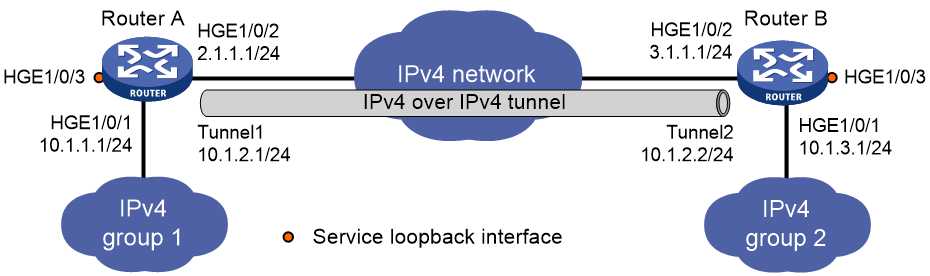
Network configuration
As shown in Figure 2, the two subnets IPv4 group 1 and IPv4 group 2 use private IPv4 addresses. Configure an IPv4 over IPv4 tunnel between Router A and Router B to make the two subnets reachable to each other.
Prerequisites
|
|
IMPORTANT: By default, interfaces on the devices are disabled (in ADM or Administratively Down state). To have an interface operate, you must use the undo shutdown command to enable that interface. |
Make sure Router A and Router B can reach each other through IPv4.
Procedure
1. Configure Router A:
# Specify an IPv4 address for HundredGigE 1/0/1.
<RouterA> system-view
[RouterA] interface hundredgige 1/0/1
[RouterA-HundredGigE1/0/1] ip address 10.1.1.1 255.255.255.0
[RouterA-HundredGigE1/0/1] quit
# Specify an IPv4 address for HundredGigE 1/0/2, which is the physical interface of the tunnel.
[RouterA] interface hundredgige 1/0/2
[RouterA-HundredGigE1/0/2] ip address 2.1.1.1 255.255.255.0
[RouterA-HundredGigE1/0/2] quit
# Create service loopback group 1, and specify its service type as tunnel.
[RouterA] service-loopback group 1 type tunnel
# Configure HundredGigE 1/0/3 to operate at Layer 2 mode.
[RouterA] interface hundredgige 1/0/3
[RouterA-HundredGigE1/0/3] port link-mode bridge
# Add HundredGigE 1/0/3 to service loopback group 1.
[RouterA-HundredGigE1/0/3] port service-loopback group 1
[RouterA-HundredGigE1/0/3] quit
# Create IPv4 over IPv4 tunnel interface Tunnel 1.
[RouterA] interface tunnel 1 mode ipv4-ipv4
# Specify an IPv4 address for the tunnel interface.
[RouterA-Tunnel1] ip address 10.1.2.1 255.255.255.0
# Specify the IP address of HundredGigE 1/0/2 as the source address for the tunnel interface.
[RouterA-Tunnel1] source 2.1.1.1
# Specify the IP address of HundredGigE 1/0/2 on Router B as the destination address for the tunnel interface.
[RouterA-Tunnel1] destination 3.1.1.1
[RouterA-Tunnel1] quit
# Configure a static route destined for IPv4 group 2 through the tunnel interface.
[RouterA] ip route-static 10.1.3.0 255.255.255.0 tunnel 1
2. Configure Router B:
# Specify an IPv4 address for HundredGigE 1/0/1.
<RouterB> system-view
[RouterB] interface hundredgige 1/0/1
[RouterB-HundredGigE1/0/1] ip address 10.1.3.1 255.255.255.0
[RouterB-HundredGigE1/0/1] quit
# Specify an IPv4 address for HundredGigE 1/0/2, which is the physical interface of the tunnel.
[RouterB] interface hundredgige 1/0/2
[RouterB-HundredGigE1/0/2] ip address 3.1.1.1 255.255.255.0
[RouterB-HundredGigE1/0/2] quit
# Create service loopback group 1, and specify its service type as tunnel.
[RouterB] service-loopback group 1 type tunnel
# Configure HundredGigE 1/0/3 to operate at Layer 2 mode.
[RouterB] interface hundredgige 1/0/3
[RouterB-HundredGigE1/0/3] port link-mode bridge
# Add HundredGigE 1/0/3 to service loopback group 1.
[RouterB-HundredGigE1/0/3] port service-loopback group 1
[RouterB-HundredGigE1/0/3] quit
# Create IPv4 over IPv4 tunnel interface Tunnel 2.
[RouterB] interface tunnel 2 mode ipv4-ipv4
# Specify an IPv4 address for the tunnel interface.
[RouterB-Tunnel2] ip address 10.1.2.2 255.255.255.0
# Specify the IP address of HundredGigE 1/0/2 as the source address for the tunnel interface.
[RouterB-Tunnel2] source 3.1.1.1
# Specify the IP address of HundredGigE 1/0/2 on Router A as a destination address for the tunnel interface.
[RouterB-Tunnel2] destination 2.1.1.1
[RouterB-Tunnel2] quit
# Configure a static route destined for IPv4 group 1 through the tunnel interface.
[RouterB] ip route-static 10.1.1.0 255.255.255.0 tunnel 2
Verifying the configuration
# Use the display interface tunnel command to display the status of the tunnel interfaces on Router A and Router B. Verify that the tunnel interfaces are up. (Details not shown.)
# Verify that Router A and Router B can ping the IPv4 address of the peer interface HundredGigE 1/0/1. This example uses Router A.
[RouterA] ping -a 10.1.1.1 10.1.3.1
Ping 10.1.3.1 (10.1.3.1) from 10.1.1.1: 56 data bytes, press CTRL_C to break
56 bytes from 10.1.3.1: icmp_seq=0 ttl=255 time=2.000 ms
56 bytes from 10.1.3.1: icmp_seq=1 ttl=255 time=1.000 ms
56 bytes from 10.1.3.1: icmp_seq=2 ttl=255 time=0.000 ms
56 bytes from 10.1.3.1: icmp_seq=3 ttl=255 time=1.000 ms
56 bytes from 10.1.3.1: icmp_seq=4 ttl=255 time=1.000 ms
--- Ping statistics for 10.1.3.1 ---
5 packet(s) transmitted, 5 packet(s) received, 0.0% packet loss
round-trip min/avg/max/std-dev = 0.000/1.000/2.000/0.632 ms