- Table of Contents
-
- 01-Fundamentals Configuration Guide
- 00-Preface
- 01-CLI configuration
- 02-RBAC configuration
- 03-Login management configuration
- 04-FTP and TFTP configuration
- 05-File system management configuration
- 06-Configuration file management configuration
- 07-Software upgrade configuration
- 08-ISSU configuration
- 09-Automatic configuration
- 10-Device management configuration
- 11-Tcl configuration
- 12-Python configuration
- 13-License management
- Related Documents
-
| Title | Size | Download |
|---|---|---|
| 10-Device management configuration | 168.97 KB |
Device management tasks at a glance
Restrictions and guidelines for configuring the system time
System time configuration tasks at a glance
Setting the system time at the CLI
Obtaining the UTC time through a time protocol
Setting the daylight saving time
Enabling displaying the copyright statement
Disabling password recovery capability
Setting the port status detection timer
Setting memory alarm thresholds
Restrictions and guidelines for device reboot
Rebooting devices immediately at the CLI
Restoring the factory-default configuration
Configuring the VM password agent service
Display and maintenance commands for device management configuration
Managing the device
About device management
This chapter describes how to configure basic device parameters and manage the device.
Device management tasks at a glance
All device management tasks are optional. You can perform any of the tasks in any order.
· Configuring basic parameters
¡ Enabling displaying the copyright statement
· Configuring security parameters
¡ Disabling password recovery capability
· Adjusting device capacities
¡ Setting the port status detection timer
· Monitoring the device
¡ Setting memory alarm thresholds
· Maintaining the device
¡ Restoring the factory-default configuration
· Configuring the VM password agent service
Configuring the device name
About this task
A device name (also called hostname) identifies a device in a network and is used in CLI view prompts. For example, if the device name is Sysname, the user view prompt is <Sysname>.
Procedure
1. Enter system view.
system-view
sysname sysname
By default, the device name is H3C.
Configuring the system ID
About this task
You can use the system ID to indicate the position or functionality of the device or any other information.
Procedure
1. Enter system view.
system-view
2. Configure the system ID.
sysid system-id
By default, the device does not have a system ID.
Configuring the system time
About the system time
Correct system time is essential to network management and communication. Configure the system time correctly before you run the device on the network.
The device can use one of the following methods to obtain the system time:
· Uses the locally set system time, and then uses the clock signals generated by its built-in crystal oscillator to maintain the system time.
· Periodically obtains the UTC time from an NTP source, and uses the UTC time, time zone, and daylight saving time to calculate the system time. For more information about NTP, see Network Management and Monitoring Configuration Guide.
The system time calculated by using the UTC time from a time source is more precise.
Restrictions and guidelines for configuring the system time
After you configure the clock protocol none command, the clock datetime command determines the system time, whether or not the time zone or daylight saving time has been configured.
If you configure or change the time zone or daylight saving time after the device obtains the system time, the device recalculates the system time. To view the system time, use the display clock command.
System time configuration tasks at a glance
To configure the system time, perform the following tasks:
1. Configuring the system time
Choose one of the following tasks:
¡ Setting the system time at the CLI
¡ Obtaining the UTC time through a time protocol
2. (Optional.) Setting the time zone
Make sure each network device uses the time zone of the place where the device resides.
3. (Optional.) Setting the daylight saving time
Make sure each network device uses the daylight saving time parameters of the place where the device resides.
Setting the system time at the CLI
1. Enter system view.
system-view
2. Configure the device to use the local system time.
clock protocol none
By default, the device uses the NTP time source.
If you execute the clock protocol command multiple times, the most recent configuration takes effect.
3. Return to user view.
quit
4. Set the local system time.
clock datetime time date
By default, the system time is UTC time 00:00:00 01/01/2011.
Obtaining the UTC time through a time protocol
Restrictions and guidelines
If the NTP or PTP signals are lost, the device uses the clock signals generated by its built-in crystal oscillator to maintain the system time. After the NTP or PTP signals recover, the device obtains the UTC time again through NTP or PTP.
Procedure
1. Enter system view.
system-view
2. Specify the protocol for obtaining the UTC time.
clock protocol ntp
By default, the device uses the NTP time source.
If you execute the clock protocol command multiple times, the most recent configuration takes effect.
3. Configure time protocol parameters.
For more information about NTP configuration, see Network Management and Monitoring Configuration Guide.
Setting the time zone
1. Enter system view.
system-view
2. Set the time zone.
clock timezone zone-name { add | minus } zone-offset
By default, the system uses the UTC time zone.
Setting the daylight saving time
1. Enter system view.
system-view
2. Set the daylight saving time.
clock summer-time name start-time start-date end-time end-date add-time
By default, the daylight saving time is not set.
Enabling displaying the copyright statement
About this task
This feature enables the device to display the copyright statement in the following situations:
· When a Telnet or SSH user logs in.
· When a console user quits user view. This is because the device automatically tries to restart the user session.
If you disable displaying the copyright statement, the device does not display the copyright statement in any situations.
Procedure
1. Enter system view.
system-view
2. Enable displaying the copyright statement.
copyright-info enable
By default, displaying the copyright statement is enabled.
Configuring banners
About this task
Banners are messages that the system displays when a user logs in.
The system supports the following banners:
· Legal banner—Appears after the copyright statement. To continue login, the user must enter Y or press Enter. To quit the process, the user must enter N. Y and N are case insensitive.
· Message of the Day (MOTD) banner—Appears after the legal banner and before the login banner.
· Login banner—Appears only when password or scheme authentication is configured.
· Shell banner—Appears before the user enters user view.
The system displays the banners in the following order: legal banner, MOTD banner, login banner, and shell banner.
Banner input methods
You can configure a banner by using one of the following methods:
· Input the entire command line in a single line.
The banner cannot contain carriage returns. The entire command line, including the command keywords, the banner, and the delimiters, can have a maximum of 511 characters. The delimiters for the banner can be any printable character but must be the same. You cannot press Enter before you input the end delimiter.
For example, you can configure the shell banner "Have a nice day." as follows:
<System> system-view
[System] header shell %Have a nice day.%
· Input the command line in multiple lines.
The banner can contain carriage returns. A carriage return is counted as two characters.
To input a banner configuration command line in multiple lines, use one of the following methods:
¡ Press Enter after the final command keyword, type the banner, and end the final line with the delimiter character %. The banner plus the delimiter can have a maximum of 1999 characters.
For example, you can configure the banner "Have a nice day." as follows:
<System> system-view
[System] header shell
Please input banner content, and quit with the character '%'.
Have a nice day.%
¡ After you type the final command keyword, type any printable character as the start delimiter for the banner and press Enter. Then, type the banner and end the final line with the same delimiter. The banner plus the end delimiter can have a maximum of 1999 characters.
For example, you can configure the banner "Have a nice day." as follows:
<System> system-view
[System] header shell A
Please input banner content, and quit with the character 'A'.
Have a nice day.A
¡ After you type the final command keyword, type the start delimiter and part of the banner. Make sure the final character of the final string is different from the start delimiter. Then, press Enter, type the rest of the banner, and end the final line with the same delimiter. The banner plus the start and end delimiters can have a maximum of 2002 characters.
For example, you can configure the banner "Have a nice day." as follows:
<System> system-view
[System] header shell AHave a nice day.
Please input banner content, and quit with the character 'A'.
A
Procedure
1. Enter system view.
system-view
2. Configure the legal banner.
header legal text
3. Configure the MOTD banner.
header motd text
4. Configure the login banner.
header login text
5. Configure the shell banner.
header shell text
Disabling password recovery capability
About this task
Password recovery capability controls console user access to the device configuration and SDRAM from BootWare menus. For more information about BootWare menus, see the release notes.
If password recovery capability is enabled, a console user can access the device configuration without authentication to configure a new password.
If password recovery capability is disabled, console users must restore the factory-default configuration before they can configure new passwords. Restoring the factory-default configuration deletes the next-startup configuration files.
To enhance system security, disable password recovery capability.
(In IRF mode.) To access the device configuration without authentication, you must connect to the master device and access the BootWare menu while the master device is starting up.
Procedure
1. Enter system view.
system-view
2. Disable password recovery capability.
undo password-recovery enable
By default, password recovery capability is enabled.
Setting the port status detection timer
About this task
The device starts a port status detection timer when a port is shut down by a protocol. Once the timer expires, the device brings up the port so the port status reflects the port's physical status.
Procedure
1. Enter system view.
system-view
2. Set the port status detection timer.
shutdown-interval time
The default setting is 30 seconds.
Monitoring CPU usage
About this task
To monitor CPU usage, the device performs the following operations:
· Samples CPU usage at 1-minute intervals and compares the samples with the CPU usage threshold and the CPU usage recovery threshold.
¡ If a sample is greater than or equal to the CPU usage threshold, the device determines the CPU usage is high and sends traps to affected service modules and processes.
¡ If a sample decreases to or below the CPU usage recovery threshold, the device determines the CPU usage has recovered and sends traps to affected service modules and processes.
· Samples and saves CPU usage at a configurable interval if CPU usage tracking is enabled. You can use the display cpu-usage history command to display the historical CPU usage statistics in a coordinate system.
Procedure
1. Enter system view.
system-view
2. Set the CPU usage alarm thresholds.
In standalone mode:
monitor cpu-usage threshold severe-threshold recovery-threshold recovery-threshold
In IRF mode:
monitor cpu-usage threshold severe-threshold recovery-threshold recovery-threshold [ slot slot-number [ cpu cpu-number ] ]
By default, the CPU usage alarm threshold is 99%.
3. Set the sampling interval for CPU usage tracking.
In standalone mode:
monitor cpu-usage interval interval
In IRF mode:
monitor cpu-usage interval interval [ slot slot-number [ cpu cpu-number ] ]
By default, the sampling interval for CPU usage tracking is 1 minute.
4. Enable CPU usage tracking.
In standalone mode:
monitor cpu-usage enable
In IRF mode:
monitor cpu-usage enable [ slot slot-number [ cpu cpu-number ] ]
By default, CPU usage tracking is enabled.
Monitoring CPU core usage
About this task
The device samples CPU core usage at 5-second intervals and calculates the average value during each CPU core usage statistics interval. If the value during an interval is greater than the CPU core usage threshold, the device issues an alarm and logs the event.
Restrictions and guidelines
As a best practice, set this argument to a multiple of the sampling interval, which is fixed at 5 seconds. If you do not do so, the actual statistics interval is the biggest multiple of the sampling interval that is smaller than the setting. For example, if you set this argument to 12 seconds, the actual statistics interval is 10 seconds.
Procedure
1. Enter system view.
system-view
2. Set CPU core usage statistics intervals.
In standalone mode:
monitor cpu-usage statistics-interval interval core core-id-list
In IRF mode:
monitor cpu-usage statistics-interval interval slot slot-number cpu cpu-number core core-id-list
By default, the CPU core usage statistics interval is 60 seconds.
3. Set CPU core alarm resending intervals.
In standalone mode:
monitor resend cpu-usage core-interval core-interval
In IRF mode:
monitor resend cpu-usage core-interval core-interval [ slot slot-number [ cpu cpu-number ] ]
By default, the CPU core alarm resending interval is 300 seconds.
4. Set CPU core usage alarm thresholds.
In standalone mode:
monitor cpu-usage threshold severe-threshold [ recovery-threshold recovery-threshold ] core core-id-list
In IRF mode:
monitor cpu-usage threshold severe-threshold [ recovery-threshold recovery-threshold ] slot slot-number cpu cpu-number core core-id-list
By default, the CPU core usage alarm threshold is 80%.
Setting memory alarm thresholds
About memory alarm threholds
To ensure correct operation and improve memory efficiency, the system performs the following operations:
· Samples memory usage at 1-minute intervals. If the sample is equal to or greater than the memory usage threshold, the device sends a trap.
· Monitors the amount of free memory space in real time. If the amount of free memory space reaches the minor, severe, or critical alarm threshold, the system issues an alarm to affected service modules and processes.
As shown in Table 1 and Figure 1, the system supports the following free-memory thresholds:
· Normal state threshold.
· Minor alarm threshold.
· Severe alarm threshold.
· Critical alarm threshold.
Table 1 Memory alarm notifications and memory alarm-removed notifications
|
Notification |
Triggering condition |
Remarks |
|
Minor alarm notification |
The amount of free memory space decreases below the minor alarm threshold. |
After generating and sending a minor alarm notification, the system does not generate and send any additional minor alarm notifications until the minor alarm is removed. |
|
Severe alarm notification |
The amount of free memory space decreases below the severe alarm threshold. |
After generating and sending a severe alarm notification, the system does not generate and send any additional severe alarm notifications until the severe alarm is removed. |
|
Critical alarm notification |
The amount of free memory space decreases below the critical alarm threshold. |
After generating and sending a critical alarm notification, the system does not generate and send any additional critical alarm notifications until the critical alarm is removed. |
|
Critical alarm-removed notification |
The amount of free memory space increases above the severe alarm threshold. |
N/A |
|
Severe alarm-removed notification |
The amount of free memory space increases above the minor alarm threshold. |
N/A |
|
Minor alarm-removed notification |
The amount of free memory space increases above the normal state threshold. |
N/A |
Figure 1 Memory alarm notifications and alarm-removed notifications

About memory alarm threholds
To ensure correct operation and improve memory efficiency, the system performs the following operations:
· Samples memory usage at 1-minute intervals. If the sample is equal to or greater than the memory usage threshold, the device sends a trap.
· Monitors the amount of free memory space in real time. If the amount of free memory space reaches the minor, severe, or critical alarm threshold, the system issues an alarm to affected service modules and processes.
The early warning feature warns you of an approaching insufficient-memory condition.
As shown in Table 1 and Figure 1, the system supports the following free-memory thresholds:
· Sufficient-memory threshold.
· Early-warning threshold.
· Normal state threshold.
· Minor alarm threshold.
· Severe alarm threshold.
· Critical alarm threshold.
Table 2 Memory alarm notifications and memory alarm-removed notifications
|
Notification |
Triggering condition |
Remarks |
|
Early-warning notification |
The amount of free memory space decreases below the early-warning threshold. |
After generating and sending an early-warning notification, the system does not generate and send any additional early-warning notifications until the early warning is removed. |
|
Minor alarm notification |
The amount of free memory space decreases below the minor alarm threshold. |
After generating and sending a minor alarm notification, the system does not generate and send any additional minor alarm notifications until the minor alarm is removed. |
|
Severe alarm notification |
The amount of free memory space decreases below the severe alarm threshold. |
After generating and sending a severe alarm notification, the system does not generate and send any additional severe alarm notifications until the severe alarm is removed. |
|
Critical alarm notification |
The amount of free memory space decreases below the critical alarm threshold. |
After generating and sending a critical alarm notification, the system does not generate and send any additional critical alarm notifications until the critical alarm is removed. |
|
Critical alarm-removed notification |
The amount of free memory space increases above the severe alarm threshold. |
N/A |
|
Severe alarm-removed notification |
The amount of free memory space increases above the minor alarm threshold. |
N/A |
|
Minor alarm-removed notification |
The amount of free memory space increases above the normal state threshold. |
N/A |
|
Early-warning alarm-removed notification |
The amount of free memory space increases above the sufficient-memory threshold. |
N/A |
Figure 2 Memory alarm notifications and alarm-removed notifications

Restrictions and guidelines
If a memory alarm occurs, delete unused configuration items or disable some features to increase the free memory space. Because the memory space is insufficient, some configuration items might not be able to be deleted.
Procedure
1. Enter system view.
system-view
2. Set the memory usage threshold.
In standalone mode:
memory-threshold usage memory-threshold
In IRF mode:
memory-threshold [ slot slot-number [ cpu cpu-number ] ] usage memory-threshold
By default, the memory usage threshold is 100%.
3. Set the free-memory thresholds.
In standalone mode:
memory-threshold [ ratio ] minor minor-value severe severe-value critical critical-value normal normal-value
In IRF mode:
memory-threshold [ slot slot-number [ cpu cpu-number ] ] [ ratio ] minor minor-value severe severe-value critical critical-value normal normal-value
The default settings vary by device model. To view the default settings, use the undo memory-threshold command to restore the default settings and then execute the display memory-threshold command.
Scheduling a task
About task scheduling
You can schedule the device to automatically execute a command or a set of commands without administrative interference.
You can configure a periodic schedule or a non-periodic schedule. A non-periodic schedule is not saved to the configuration file and is lost when the device reboots. A periodic schedule is saved to the startup configuration file and is automatically executed periodically.
Restrictions and guidelines
· The default system time is always restored at reboot. To make sure a task schedule can be executed as expected, reconfigure the system time or configure NTP after you reboot the device. For more information about NTP, see Network Management and Monitoring Configuration Guide.
· To assign a command (command A) to a job, you must first assign the job the command or commands for entering the view of command A.
· Make sure all commands in a schedule are compliant to the command syntax. The system does not check the syntax when you assign a command to a job.
· A schedule cannot contain any one of these commands: telnet, ftp, ssh2, and monitor process.
· A schedule does not support user interaction. If a command requires a yes or no answer, the system always assumes that a Y or Yes is entered. If a command requires a character string input, the system assumes that either the default character string (if any) or a null string is entered.
· A schedule is executed in the background, and no output (except for logs, traps, and debug information) is displayed for the schedule.
Procedure
1. Enter system view.
system-view
2. Create a job.
scheduler job job-name
3. Assign a command to the job.
command id command
By default, no command is assigned to a job.
You can assign multiple commands to a job. A command with a smaller ID is executed first.
4. Exit to system view.
quit
5. Create a schedule.
scheduler schedule schedule-name
6. Assign a job to the schedule.
job job-name
By default, no job is assigned to a schedule.
You can assign multiple jobs to a schedule. The jobs will be executed concurrently.
7. Assign user roles to the schedule.
user-role role-name
By default, a schedule has the user role of the schedule creator.
You can assign a maximum of 64 user roles to a schedule. A command in a schedule can be executed if it is permitted by one or more user roles of the schedule.
8. Specify the execution time for the schedule.
Choose one option as needed:
¡ Execute the schedule at specific points of time.
time at time date
time once at time [ month-date month-day | week-day week-day&<1-7> ]
¡ Execute the schedule after a period of time.
time once delay time
¡ Execute the schedule at the specified time on every specified day in a month or week.
time repeating at time [ month-date [ month-day | last ] | week-day week-day&<1-7> ]
¡ Execute the schedule periodically from the specified time on.
time repeating [ at time [date ] ] interval interval
By default, no execution time is specified for a schedule.
The time commands overwrite each other. The most recently configured command takes effect.
9. (Optional.) Set the size of the job execution log file.
scheduler logfile size value
By default, the size of the job execution log file is 16 KB.
The job execution log file stores the execution information of jobs. If the file is full, old records are deleted to make room for new records. If the size of the log information to be written to the file is greater than the file size, the excessive information is not written to the file.
Example: Scheduling a task
Network configuration
As shown in Figure 3, two interfaces of the device are connected to users.
To save energy, configure the device to perform the following operations:
· Enable the interfaces at 8:00 a.m. every Monday through Friday.
· Disable the interfaces at 18:00 every Monday through Friday.

Procedure
# Enter system view.
<Sysname> system-view
# Configure a job for disabling interface GigabitEthernet 1/0.
[Sysname] scheduler job shutdown-GigabitEthernet1/0
[Sysname-job-shutdown-GigabitEthernet1/0] command 1 system-view
[Sysname-job-shutdown-GigabitEthernet1/0] command 2 interface gigabitethernet 1/0
[Sysname-job-shutdown-GigabitEthernet1/0] command 3 shutdown
[Sysname-job-shutdown-GigabitEthernet1/0] quit
# Configure a job for enabling interface GigabitEthernet 1/0.
[Sysname] scheduler job start-GigabitEthernet1/0
[Sysname-job-start-GigabitEthernet1/0] command 1 system-view
[Sysname-job-start-GigabitEthernet1/0] command 2 interface gigabitethernet 1/0
[Sysname-job-start-GigabitEthernet1/0] command 3 undo shutdown
[Sysname-job-start-GigabitEthernet1/0] quit
# Configure a job for disabling interface GigabitEthernet 2/0.
[Sysname] scheduler job shutdown-GigabitEthernet2/0
[Sysname-job-shutdown-GigabitEthernet2/0] command 1 system-view
[Sysname-job-shutdown-GigabitEthernet2/0] command 2 interface gigabitethernet 2/0
[Sysname-job-shutdown-GigabitEthernet2/0] command 3 shutdown
[Sysname-job-shutdown-GigabitEthernet2/0] quit
# Configure a job for enabling interface GigabitEthernet 2/0.
[Sysname] scheduler job start-GigabitEthernet2/0
[Sysname-job-start-GigabitEthernet2/0] command 1 system-view
[Sysname-job-start-GigabitEthernet2/0] command 2 interface gigabitethernet 2/0
[Sysname-job-start-GigabitEthernet2/0] command 3 undo shutdown
[Sysname-job-start-GigabitEthernet2/0] quit
# Configure a periodic schedule for enabling the interfaces at 8:00 a.m. every Monday through Friday.
[Sysname] scheduler schedule START-pc1/pc2
[Sysname-schedule-START-pc1/pc2] job start-GigabitEthernet1/0
[Sysname-schedule-START-pc1/pc2] job start-GigabitEthernet2/0
[Sysname-schedule-START-pc1/pc2] time repeating at 8:00 week-day mon tue wed thu fri
[Sysname-schedule-START-pc1/pc2] quit
# Configure a periodic schedule for disabling the interfaces at 18:00 every Monday through Friday.
[Sysname] scheduler schedule STOP-pc1/pc2
[Sysname-schedule-STOP-pc1/pc2] job shutdown-GigabitEthernet1/0
[Sysname-schedule-STOP-pc1/pc2] job shutdown-GigabitEthernet2/0
[Sysname-schedule-STOP-pc1/pc2] time repeating at 18:00 week-day mon tue wed thu fri
[Sysname-schedule-STOP-pc1/pc2] quit
Verifying the configuration
# Display the configuration information of all jobs.
[Sysname] display scheduler job
Job name: shutdown-GigabitEthernet1/0
system-view
interface gigabitethernet 1/0
shutdown
Job name: shutdown-GigabitEthernet2/0
system-view
interface gigabitethernet 2/0
shutdown
Job name: start-GigabitEthernet1/0
system-view
interface gigabitethernet 1/0
undo shutdown
Job name: start-GigabitEthernet2/0
system-view
interface gigabitethernet 2/0
undo shutdown
# Display the schedule information.
[Sysname] display scheduler schedule
Schedule name : START-pc1/pc2
Schedule type : Run on every Mon Tue Wed Thu Fri at 08:00:00
Start time : Wed Sep 28 08:00:00 2011
Last execution time : Wed Sep 28 08:00:00 2011
Last completion time : Wed Sep 28 08:00:03 2011
Execution counts : 1
-----------------------------------------------------------------------
Job name Last execution status
start-GigabitEthernet1/0 Successful
start-GigabitEthernet2/0 Successful
Schedule name : STOP-pc1/pc2
Schedule type : Run on every Mon Tue Wed Thu Fri at 18:00:00
Start time : Wed Sep 28 18:00:00 2011
Last execution time : Wed Sep 28 18:00:00 2011
Last completion time : Wed Sep 28 18:00:01 2011
Execution counts : 1
-----------------------------------------------------------------------
Job name Last execution status
shutdown-GigabitEthernet1/0 Successful
shutdown-GigabitEthernet2/0 Successful
# Display schedule log information.
[Sysname] display scheduler logfile
Job name : start-GigabitEthernet1/0
Schedule name : START-pc1/pc2
Execution time : Wed Sep 28 08:00:00 2011
Completion time : Wed Sep 28 08:00:02 2011
--------------------------------- Job output -----------------------------------
<Sysname>system-view
System View: return to User View with Ctrl+Z.
[Sysname]interface gigabitethernet 1/0
[Sysname-GigabitEthernet1/0]undo shutdown
Job name : start-GigabitEthernet2/0
Schedule name : START-pc1/pc2
Execution time : Wed Sep 28 08:00:00 2011
Completion time : Wed Sep 28 08:00:02 2011
--------------------------------- Job output -----------------------------------
<Sysname>system-view
System View: return to User View with Ctrl+Z.
[Sysname]interface gigabitethernet 2/0
[Sysname-GigabitEthernet2/0]undo shutdown
Job name : shutdown-GigabitEthernet1/0
Schedule name : STOP-pc1/pc2
Execution time : Wed Sep 28 18:00:00 2011
Completion time : Wed Sep 28 18:00:01 2011
--------------------------------- Job output -----------------------------------
<Sysname>system-view
System View: return to User View with Ctrl+Z.
[Sysname]interface gigabitethernet 1/0
[Sysname-GigabitEthernet1/0]shutdown
Job name : shutdown-GigabitEthernet2/0
Schedule name : STOP-pc1/pc2
Execution time : Wed Sep 28 18:00:00 2011
Completion time : Wed Sep 28 18:00:01 2011
--------------------------------- Job output -----------------------------------
<Sysname>system-view
System View: return to User View with Ctrl+Z.
[Sysname]interface gigabitethernet 2/0
[Sysname-GigabitEthernet2/0]shutdown
Rebooting the device
About device reboot
The following device reboot methods are available:
· Schedule a reboot at the CLI, so the device automatically reboots at the specified time or after the specified period of time.
· Immediately reboot the device at the CLI.
During the reboot process, the device performs the following operations:
a. Resets all of its chips.
b. Uses the BootWare to verify the startup software package, decompress the package, and load the images.
c. Initializes the system.
· Power off and then power on the device. This method might cause data loss, and is the least-preferred method.
Using the CLI, you can reboot the device from a remote host.
Restrictions and guidelines for device reboot
A device reboot might result in a service outage.
For data security, the device does not reboot while it is performing file operations.
Rebooting devices immediately at the CLI
Prerequisites
Perform the following steps in any view:
1. Verify that the next-startup configuration file is correctly specified.
display startup
For more information about the display startup command, see Fundamentals Command Reference.
2. Verify that the startup image files are correctly specified.
display boot-loader
If one main startup image file is damaged or does not exist, you must specify another main startup image file before rebooting the device.
For more information about the display boot-loader command, see Fundamentals Command Reference.
3. Save the running configuration to the next-startup configuration file.
save
To avoid configuration loss, save the running configuration before a reboot.
For more information about the save command, see Fundamentals Command Reference.
Procedure
To reboot the device immediately at the CLI, execute one of the following commands in user view:
In standalone mode:
reboot [ force ]
In IRF mode:
reboot [ slot slot-number ] [ force ]
Scheduling a device reboot
Restrictions and guidelines
(In IRF mode.) The automatic reboot configuration takes effect on all member devices. It will be canceled if a master/subordinate switchover occurs.
The device supports only one device reboot schedule. If you execute the scheduler reboot command multiple times, the most recent configuration takes effect.
Procedure
To schedule a reboot, execute one of the following commands in user view:
· scheduler reboot at time [ date ]
· scheduler reboot delay time
By default, no device reboot time is specified.
Restoring the factory-default configuration
About this task
If you want to use the device in a different scenario or you cannot troubleshoot the device by using other methods, use this task to restore the factory-default configuration.
This task does not delete .bin files and license files.
Restrictions and guidelines
|
|
CAUTION: This command is disruptive. It restores the factory default configuration and forcibly reboots the device. |
Procedure
To restore the factory-default configuration for the device, execute the following command in user view:
restore factory-default
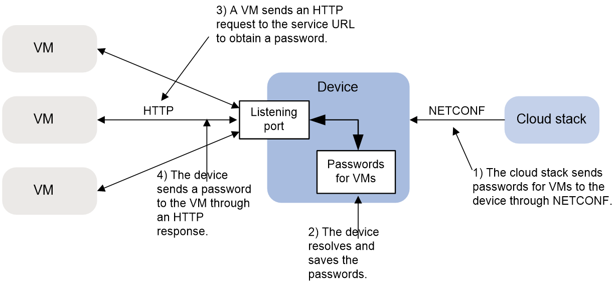
Configuring the VM password agent service
About this task
The device can act as the VM password agent to perform the following operations:
· Receive, resolve, and save passwords from the cloud stack.
· Assign and send passwords to VMs in response to password requests.
Figure 4 shows the VM password agent service work flow.
VMs obtain passwords from the device through HTTP. The URL used for the HTTP request contains the following parameters:
· IP address of the device.
· Listening port number for the VM password agent service.
· Relative path for the VM password agent service.
Make sure the device and the VMs use the same parameters.
Figure 4 VM password agent service work flow
Procedure
1. Enter system view.
system-view
2. Enable the VM password agent service.
vmman http enable
Be default, the VM password agent service is disabled.
3. Specify the listening port for the service.
vmman http port port-number
By default, the listening port is 8080 for the VM password agent service.
4. Specify the relative path for the service.
vmman http url relative-path
By default, the relative path is / for the VM password agent service.
Display and maintenance commands for device management configuration
Execute display commands in any view. Execute the reset scheduler logfile command in user view. Execute the reset version-update-record command in system view.
|
Task |
Command |
|
Display the system time, date, time zone, and daylight saving time. |
display clock |
|
Display the copyright statement. |
display copyright |
|
Display CPU usage statistics. |
In standalone mode: display cpu-usage [ summary ] [ cpu cpu-number [ core { core-number | all } ] ] display cpu-usage [ summary ] In IRF mode: display cpu-usage [ summary ] [ slot slot-number [ cpu cpu-number [ core { core-number | all } ] ] ] display cpu-usage [ summary ] [ slot slot-number [ cpu cpu-number ] ] |
|
Display CPU usage monitoring settings. |
In standalone mode: display cpu-usage configuration In IRF mode: display cpu-usage configuration [ slot slot-number [ cpu cpu-number ] ] |
|
Display the historical CPU usage statistics in a coordinate system. |
In standalone mode: display cpu-usage history [ job job-id ] In IRF mode: display cpu-usage history [ job job-id ] [ slot slot-number [ cpu cpu-number ] ] |
|
Display hardware information. |
In standalone mode: display device [ harddisk | usb ] [ verbose ] In IRF mode: display device [ harddisk | usb ] [ slot slot-number | verbose ] |
|
Display or save operating information for features and hardware modules. |
display diagnostic-information [ hardware | infrastructure | l2 | l3 | service ] [ key-info ] [ filename ] |
|
Display memory usage statistics. |
In standalone mode: display memory [ summary ] In IRF mode: display memory [ summary ] [ slot slot-number [ cpu cpu-number ] ] |
|
Display memory alarm thresholds and statistics. |
In standalone mode: display memory-threshold In IRF mode: display memory-threshold [ slot slot-number [ cpu cpu-number ] ] |
|
Display job configuration information. |
display scheduler job [ job-name ] |
|
Display job execution log information. |
display scheduler logfile |
|
Display the automatic reboot schedule. |
display scheduler reboot |
|
Display schedule information. |
display scheduler schedule [ schedule-name ] |
|
Display system stability and status information. |
display system stable state |
|
Display system version information. |
display version |
|
Display startup software image upgrade records. |
display version-update-record |
|
Clear job execution log information. |
reset scheduler logfile |
|
Clear startup software image upgrade records. |
reset version-update-record |
