- Table of Contents
- Related Documents
-
| Title | Size | Download |
|---|---|---|
| 01-Chassis Views and Technical Specifications | 910.11 KB |
Contents
1 Chassis views and technical specifications
MSR3610-I-DP/MSR3610-I-XS/MSR3610-IE-DP/MSR3610-IE-ES/MSR3610-IE-XS
1 Chassis views and technical specifications
Chassis views
The following figures are for illustration only. The label Hard Disk on the front panel refers to a drive slot.
MSR3610-I-DP/MSR3610-I-XS/MSR3610-IE-DP/MSR3610-IE-ES/MSR3610-IE-XS
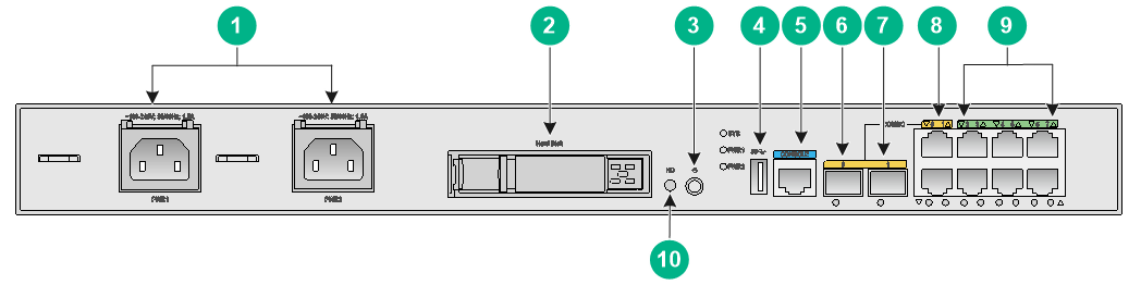
Figure1-1 Front panel
|
(2) Drive slot |
|
|
(3) Power button/LED |
(4) USB port |
|
(5) Console port (CONSOLE) |
(6) Ethernet fiber port SFP0 (combo interface) |
|
(7) Ethernet fiber port SFP1 (combo interface) |
|
|
(8) Ethernet copper ports GE0 and GE1 (combo interfaces) |
|
|
(9) Ethernet copper ports GE2 to GE7 |
(10) Drive button (HD) |
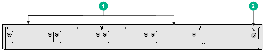
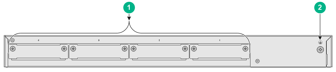
Figure1-2 Rear panel
|
(1) SIC interface module slots 1 to 4 |
(2) Grounding screw |
MSR3610-IE-EAD
Figure1-3 Front panel

|
(1) AC power receptacles PWR1 and PWR2 |
(2) Drive slot |
|
(3) Power button/LED |
(4) USB port |
|
(5) Console port (CONSOLE) |
(6) Ethernet fiber port SFP0 (combo interface) |
|
(7) Ethernet fiber port SFP1 (combo interface) |
|
|
(8) Ethernet copper ports GE0 and GE1 (combo interfaces) |
|
|
(9) Ethernet copper ports GE2 to GE7 |
(10) Drive button (HD) |
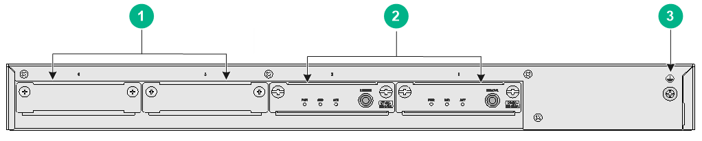
Figure1-4 Rear panel
|
(1) SIC interface module slots 3 and 4 |
(2) SIC-M2-SATA riser modules 1 and 2 |
|
(3) Grounding screw |
|
MSR3610-I-IG/3610-IE-IG
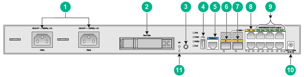
Figure1-5 Front panel
|
(1) AC power receptacles PWR1 and PWR2 |
(2) Drive slot |
|
(3) Power button/LED |
(4) USB port |
|
(5) Console port (CONSOLE) |
(6) Ethernet fiber port SFP0 (combo interface) |
|
(7) Ethernet fiber port SFP1 (combo interface) |
|
|
(8) Ethernet copper ports GE0 and GE1 (combo interfaces) |
|
|
(9) Ethernet copper ports GE2 to GE7 |
(10) PoE port |
|
(10) Drive button (HD) |
|
Figure1-6 Rear panel
|
(1) SIC interface module slots 1 to 4 |
(2) Grounding screw |
Power button
|
|
WARNING! The device might still have power after you press the power button. Do not reboot the device or remove power cords from the device until the power button/LED goes off. |
|
|
CAUTION: · Forced power-off might cause data loss in virtual machines. Please use it with caution. · Avoid accidentally pressing the power button when the device is operating. Doing so will power off the device system and cause service interruption. |
The power button is used to power on or power off the Comware system and virtual machines created on the Comware system.
If you cannot power off the virtual machines gracefully by pressing the power button for 0.5 to 3 seconds, use either of the following methods:
· Press the power button for over 3 seconds to power off the virtual machines forcibly.
· Terminate running processes on the virtual machines, and then press the power button to gracefully power off the virtual machines.
By default, pressing the power button on a powered-off device starts the Comware system but not the virtual machines. You can use the autostart command to configure the virtual machines to be started together with the Comware system.
Technical specifications
Table1-1 Technical specifications
|
Item |
MSR3610-I-DP/3610-I-XS |
MSR3610-IE-DP/3610-IE-ES/3610-IE-XS |
MSR3610-IE-EAD |
MSR3610-I-IG/3610-IE-IG |
|
Console port |
1 |
1 |
1 |
1 |
|
GE copper ports |
2 (combo interfaces) + 6 |
2 (combo interfaces) + 6 |
2 (combo interfaces) + 6 |
2 (combo interfaces) + 6 |
|
GE fiber ports |
2 (combo interfaces) |
2 (combo interfaces) |
2 (combo interfaces) |
2 (combo interfaces) |
|
USB port |
1 |
1 |
1 |
1 |
|
Drive slot |
1 (support for a 2.5-inch SATA drive) |
1 (support for a 2.5-inch SATA drive) |
1 (support for a 2.5-inch SATA drive) |
1 (support for a 2.5-inch SATA drive) |
|
SIC interface module slots |
4 |
4 |
4 |
4 |
|
AC power receptacles |
2 |
2 |
2 |
2 |
|
Memory |
8/16/32 GB DDR4 |
8/16/32 GB DDR4 |
32 GB DDR4 |
· MSR3610-I-IG: 8 GB · MSR3610-IE-IG: 16 GB |
|
Built-in storage |
4 GB EMMC |
4 GB (64 GB in total) EMMC |
4 GB (64 GB in total) EMMC |
· MSR3610-I-IG: 4 GB EMMC · MSR3610-IE-IG: 4 GB (64 GB in total) EMMC |
|
Dimensions (H × W × D) (excluding mounting brackets and rubber feet) |
43.6 × 440 × 360 mm (1.72 × 17.32 × 14.17 in) |
43.6 × 440 × 360 mm (1.72 × 17.32 × 14.17 in) |
43.6 × 440 × 360 mm (1.72 × 17.32 × 14.17 in) |
43.6 × 440 × 360 mm (1.72 × 17.32 × 14.17 in) |
|
Rated AC voltage |
100 VAC to 240 VAC @ 50 or 60 Hz |
100 VAC to 240 VAC @ 50 or 60 Hz |
100 VAC to 240 VAC @ 50 or 60 Hz |
100 VAC to 240 VAC @ 50 or 60 Hz |
|
Maximum power consumption |
54 W |
54 W |
54 W |
54 W |
|
Operating temperature |
· Without a drive: 0°C to 45°C (32°F to 113°F) · With a drive: 5°C to 40°C (41°F to 104°F) |
· Without a drive: 0°C to 45°C (32°F to 113°F) · With a drive: 5°C to 40°C (41°F to 104°F) |
· Without a drive: 0°C to 45°C (32°F to 113°F) · With a drive: 5°C to 40°C (41°F to 104°F) |
· Without a drive: –20°C to +55°C (–4°F to +131°F) · With a drive: 5°C to 40°C (41°F to 104°F) |
|
Relative humidity (non-condensing) |
· Without a drive: 5% RH to 95% RH, noncondensing · With a drive: 10% RH to 80% RH, noncondensing |
|||
Link mode of interfaces
Ethernet interfaces on the device operate differently in link mode. Interfaces that operate in bridge mode are Layer 2 interfaces. Interfaces that operate in route mode are Layer 3 interfaces.
· Some fixed Ethernet interfaces on the device operate as Layer 3 Ethernet interfaces by default. You cannot use the port link-mode command to change the operating mode of these interfaces to bridge. Table1-2 describes these interfaces.
· Some fixed Ethernet interfaces on the device operate as Layer 2 Ethernet interfaces by default. You can use the port link-mode command to change their operating mode to route. Table1-3 describes these interfaces.
For information about link mode change of interfaces on interface modules, see H3C MSR Router Series Comware 7 Interface Module Guide.
Table1-2 Fixed interfaces that can operate only as Layer 3 Ethernet interfaces
|
Device model |
Interfaces |
|
MSR3610-I-DP/MSR3610-I-XS/MSR3610-IE-DP/MSR3610-IE-ES/MSR3610-IE-XS |
Combo 0 (GE0, SFP0), Combo 1 (GE1, SFP1) |
|
MSR3610-IE-EAD |
Combo 0 (GE0, SFP0), Combo 1 (GE1, SFP1) |
|
MSR3610-I-IG/3610-IE-IG |
Combo 0 (GE0, SFP0), Combo 1 (GE1, SFP1) |
|
Device model |
Interfaces |
|
MSR3610-I-DP/MSR3610-I-XS/MSR3610-IE-DP/MSR3610-IE-ES/MSR3610-IE-XS |
GE2 to GE7 |
|
MSR3610-IE-EAD |
GE2 to GE7 |
|
MSR3610-I-IG/3610-IE-IG |
GE2 to GE7 |