- Table of Contents
- Related Documents
-
| Title | Size | Download |
|---|---|---|
| 01-Text | 1.35 MB |
Service data interaction modes of the VM
Deploying the EAD gateway in a network
Preparations for EAD gateway deployment
Preparing a management host and tool software
Connecting the management host and the EAD gateway
Configuring IP address settings for the management host
Preparing for VNC Viewer login
Configuring VM network settings
Configuring the EAD gateway through IMC
About EAD gateway configuration through IMC
Displaying IMC service running status
Example: Deploying the EAD gateway in a network
Restrictions and guidelines for RAID configuration
Partitioning the hard disks and modifying the file system format
Displaying RAID status information
Exporting the VM to a .pkg file
Display and maintenance commands for VM management
Introduction
The H3C MSR3610-I iMC EAD End-user Admission Defense Gateway (referred to as the EAD gateway hereinafter) can cooperate with access services (for example, L2TP, 802.1X, and portal) to achieve the following purposes:
· Ensure endpoint access security.
· Prevent endpoints from network threats.
· Control endpoints' network access behaviors.
To improve the high availability of authentication data, the EAD gateway is built with two SIC-M2-SATA drives operating in RAID 1 mode.
The EAD gateway is shipped with a VM that runs the CentOS operating system. The VM is installed with IMC software and EAD components by default, and it has been assigned an SR-IOV NIC with an IP address.
Factory defaults
Interfaces
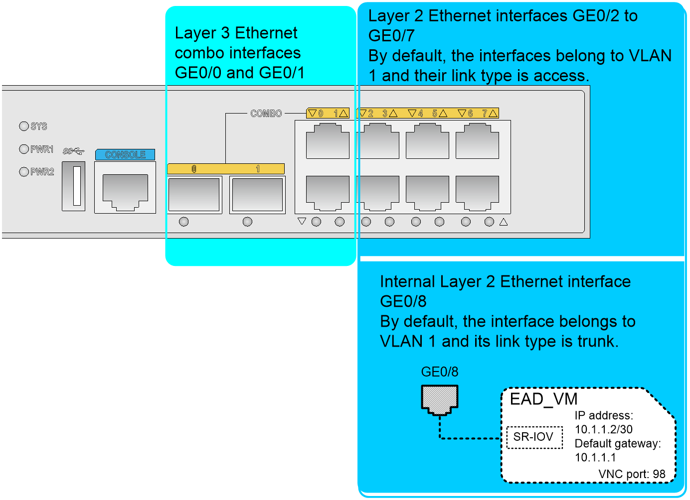
The EAD gateway provides the following interfaces by default:
· Layer 3 Ethernet combo interfaces GigabitEthernet 0/0 and GigabitEthernet 0/1.
· Layer 2 Ethernet copper interfaces GigabitEthernet 0/2 to GigabitEthernet 0/8, in which GigabitEthernet 0/8 is an internal interface used to connect the SR-IOV NIC of the VM.
Figure 1 shows the interfaces on the EAD gateway.
Figure 1 Interface network diagram
Default VM parameters
The EAD gateway is shipped with a VM. The default VM parameters are as follows:
· The VM name is EAD_VM, which is case sensitive.
· The VM operating system is CentOS.
· The login username of the VM operating system is root, which is case sensitive.
· The login password of the VM operating system is iMC123, which is case sensitive.
· The VNC port number is 98. Users can log in to the desktop of the VM by using this port number through VNC Viewer.
· The VM is assigned an SR-IOV NIC. By default, the NIC belongs to VLAN 4094.
· The IP address of the VM is 10.1.1.2/30 and the default gateway is 10.1.1.1.
· The IP address of VLAN-interface 1 is 192.168.0.1/23.
· The IP address of VLAN-interface 4094 is 10.1.1.1/30.
VM login method
To use a management host to log in to the VM, make sure the management host has routes to reach the EAD gateway.
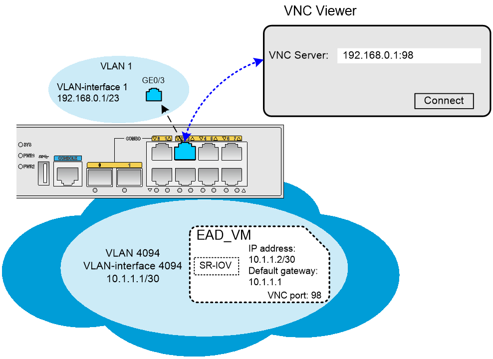
The EAD gateway allows users that use VNC Viewer to log in to the desktop of the VM by connecting to the VM VNC server in VNC server IP address:VNC port number format.
· VNC server IP address—The IP address of a Layer 3 interface or a VLAN interface on the EAD gateway.
· VNC port number—The VNC port number of the VM. The VNC port number is configurable at the CLI of the EAD gateway.
Figure 2 VM login through the IP address of a Layer 3 interface
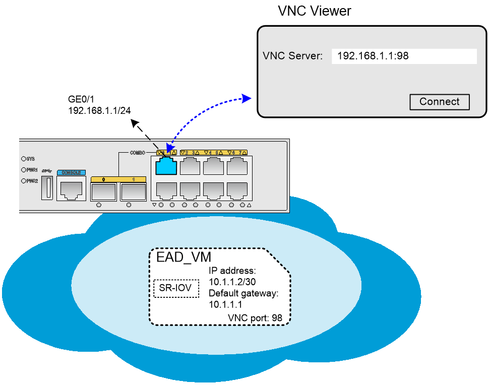
Figure 3 VM login through the IP address of a VLAN interface
VM network configuration
The VM deployed on the EAD gateway is assigned a high-performance SR-IOV NIC by default. The NIC is shipped with IP address 10.1.1.2/30 and gateway 10.1.1.1. For a client host to access the VM, use one of the following methods:
· Configure the client host to use an IP address that can reach the subnet of the VM NIC.
· Log in to the desktop of the VM and reconfigure an IP address for the VM NIC according to the user network configuration.
Service data interaction modes of the VM
The EAD gateway provides the following service data interaction modes for the VM:
· Intra-VLAN broadcasting.
· Layer 3 routing.
|
|
IMPORTANT: By default, the SR-IOV NIC of the VM on the EAD gateway belongs to VLAN 4094. |
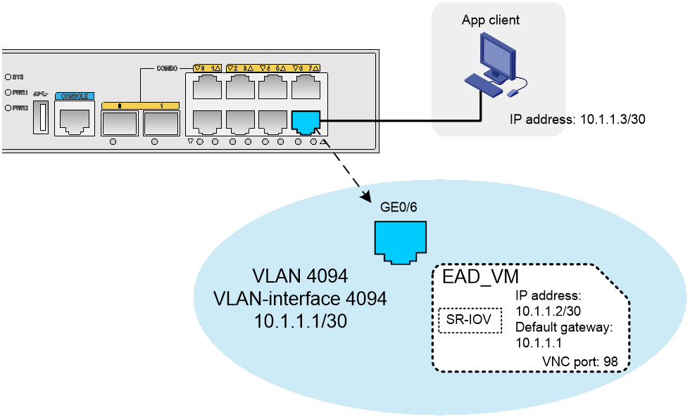
Intra-VLAN broadcasting
For a client host to access the VM, configure IP addresses for the client host and the VM that belong to the same subnet and assign them to the same VLAN. As shown in Figure 4, the client host accesses the VM through a Layer 2 Ethernet interface on the EAD gateway in the same VLAN.
Figure 4 Intra-VLAN broadcasting mode
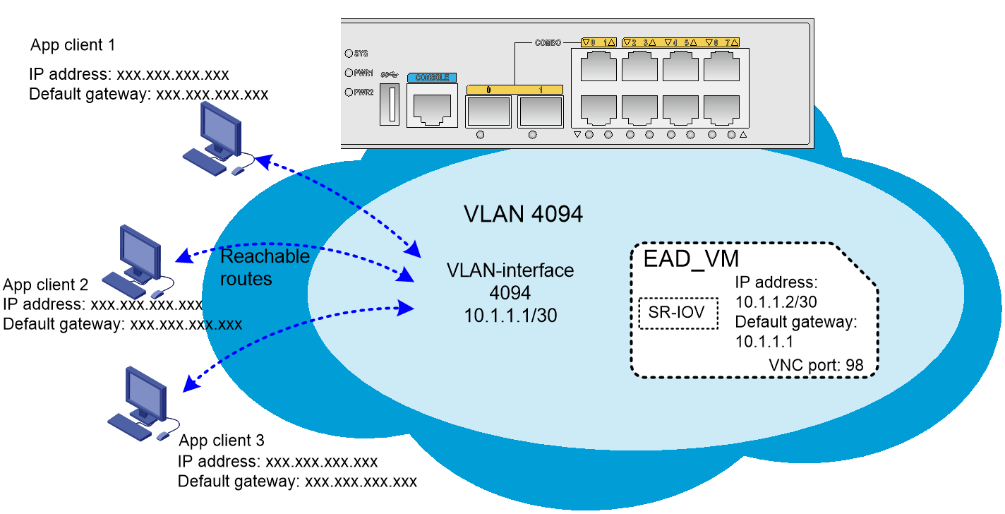
Layer 3 routing
The VM NIC belongs to a VLAN. Set the IP address of the VLAN interface to an IP address reachable to the client hosts, and specify the default gateway of the VM as the IP address of the VLAN interface. The client hosts interact with the VM through a Layer 3 Ethernet interface or VLAN interface of the EAD gateway, as shown in Figure 5.
Deploying the EAD gateway in a network
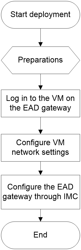
Deployment process
The EAD gateway ensures endpoint access security, controls endpoints' access behaviors, and backs up authentication data in the network. Figure 6 shows the deployment process of the EAD gateway in a network.
Preparations for EAD gateway deployment
Preparing a management host and tool software
· Prepare a management host used to log in to the VM on the EAD gateway. Prepare a serial cable and a network cable to connect the management host and the EAD gateway.
· Install a terminal emulation program (for example, PuTTY) on the management host used to log in to the CLI of the EAD gateway for VM parameter configuration and query.
· Install remote login software (for example, VNC Viewer) on the management host used to log in to the desktop of the VM and process services on the VM operating system.
Connecting the management host and the EAD gateway
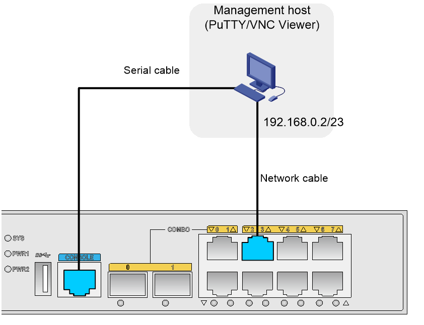
Use the serial cable to connect the management host and the console port of the EAD gateway. The management host can use the PuTTY software to log in to the CLI of the EAD gateway through the serial cable.
Use the network cable to connect the management host and GigabitEthernet 0/3 on the EAD gateway. The management host can communicate with the EAD gateway through the network cable.
Figure 7 shows the network diagram.
Figure 7 Connecting the management host and EAD gateway
Configuring IP address settings for the management host
About this task
Use one of the following methods to configure IP address settings for the management host:
· Automatic IP address assignment—By default, DHCP is enabled on the EAD gateway. If the management host chooses to dynamically obtain an IP address, the EAD gateway randomly assigns an IP address to the management host from the IP address pool. By default, the IP address pool on the EAD gateway contains IP addresses from 192.168.1.1/23 to 192.168.1.254/23.
· Manual IP address configuration—Manually configure an IP address for the management host.
Procedure
To manually configure an IP address for the management host:
1. Open the Network and Sharing Center and select Local Area Connection.
2. In the dialog box that opens, click Properties.
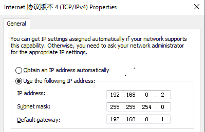
3. In the dialog box that opens, select Internet Protocol Version 4 (TCP/IPv4) and click Properties.
4. In the dialog box that opens, configure the IP address settings as shown in Figure 8.
In this example, the IP address is 192.168.0.2/23.
Figure 8 Configuring IP address settings for the management host
Verifying the configuration
# Verify that the management host can ping the EAD gateway and the EAD gateway can ping the management host. (Details not shown.)
Preparing for VNC Viewer login
About this task
To use VNC Viewer to log in to the desktop of the VM, you must obtain the VM name and VNC port number and make sure the VM has been started. Perform this task to obtain the VM name and VNC port number and view the VM status.
By default, the VM name on the EAD gateway is EAD_VM and the VNC port number is 98.
Obtaining the VM name and VM status
Log in to the CLI of the EAD gateway and use the display vmlist command to obtain the VM name and status. If the VM is in shutoff state, use the start vm command to start the VM.
# Obtain the VM name and status.
<H3C> display vmlist
Id Name Status
------------------------------------------
- EAD_VM running
# (Optional.) Start the VM.
<H3C> system-view
[H3C] vmm
[H3C-vmm] start vm EAD_VM
Domain EAD_VM started
Obtaining the VNC port number of the VM
# Obtain the VNC port number of the VM.
<H3C> display vncport vm EAD_VM
:98
Logging in to the VM
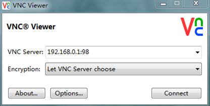
In this example, IP address 192.168.0.1/23 is used as the VNC server IP address. This IP address is the default IP address of VLAN-interface 1 on the EAD gateway.
Logging in to the desktop of the VM
1. On the management host, open VNC Viewer, and connect to the desktop of the VM by using the VNC server in the format of VNC server IP address:VNC port number, as shown in Figure 9.
Figure 9 VNC Viewer login interface
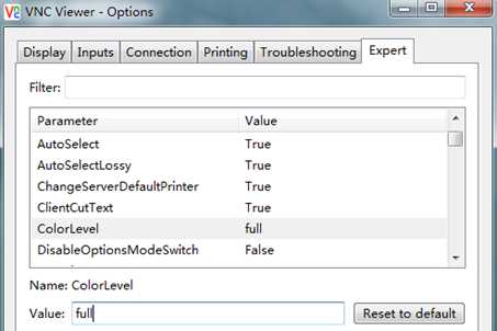
2. If VNC Viewer flashes to exit, set the VNC configuration color level to full:
a. Click Options on the login interface.
b. Click the Expert tab.
c. Select ColorLevel.
d. Set the value of ColorLevel to full as shown in Figure 10.
Figure 10 Modifying the color level
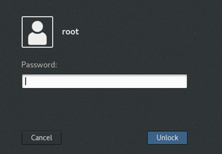
Logging in to the VM operating system
As a best practice to ensure VM security, change the default login password of the VM operating system.
After you use VNC Viewer to log in to the desktop of the VM, enter the username and password to log in to the VM operating system.
By default, the login username is root and the login password is iMC123.
As shown in Figure 11, enter the password to log in to the VM operating system.
Figure 11 Logging in to the VM operating system
Configuring VM network settings
About this task
By default, the VM IP address is 10.1.1.2/30 and the gateway is 10.1.1.1. To modify the IP address settings, perform this task.
Restrictions and guidelines
The VM NIC belongs to a VLAN. The gateway address of the VM must be the IP address of the VLAN interface.
Procedure
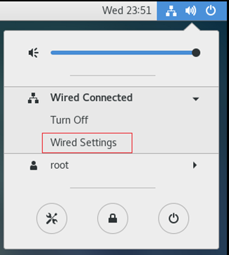
1. Select the Network Settings menu in the upper right corner of the desktop.
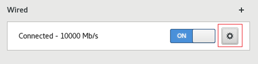
2. Select Wired Connected and click Wired Settings, as shown in Figure 12.
Figure 12 Opening the wired connection
3. Click the gear icon as shown in Figure 13.
Figure 13 Opening the network setting configuration page
4. Configure IP address settings for the VM, as shown in Figure 14.
Figure 14 Configuring IP address settings
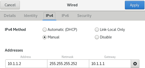
5. Verify that the management host can ping the VM. To ensure a successful ping operation, make sure the firewall of the VM is disabled. By default, the firewall of the VM is disabled. (Details not shown.)
Configuring the EAD gateway through IMC
About EAD gateway configuration through IMC
After the management host and the EAD gateway become reachable, you can access the IMC Web interface to configure the EAD gateway through the management host. For more information about IMC, see user manuals for the H3C Intelligent Management Center in the network management section of technical documents on H3C websites.
Displaying IMC service running status
The IMC services installed on the VM of the EAD gateway have been set to auto-start when the gateway is shipped. When the VM starts up, the IMC services also start up.
To view the running status of IMC services and the deployment status of the EAD component:
1. Right-click the VM desktop and select Open Terminal to enter the CLI of the CentOS system. Figure 15 shows the CLI.
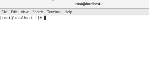
2. Open the page that displays IMC services.
[root@localhost~]# cd /opt/iMC/deploy/
[root@localhost~]# ./dma.sh
Figure 16 shows the page that displays IMC services.
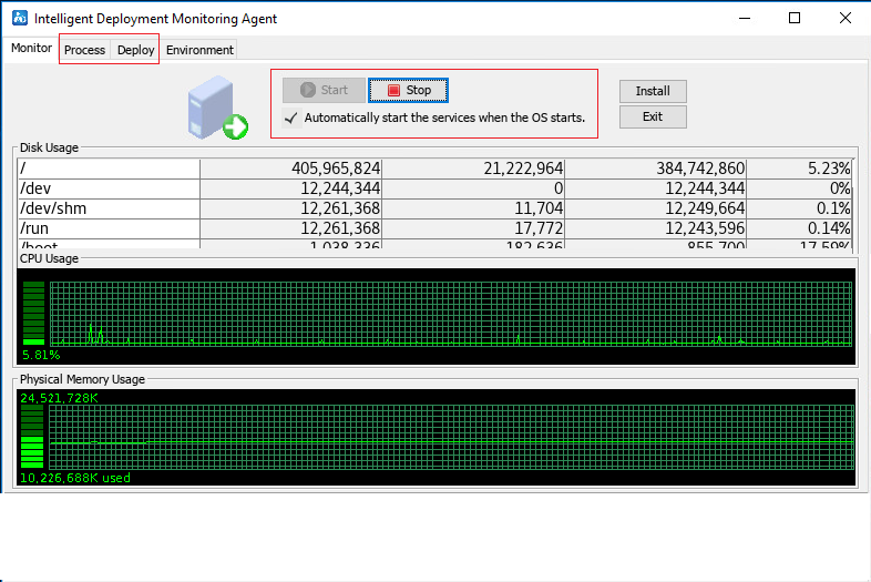
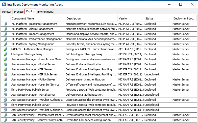
3. Click the Process and Deploy tabs to view the status of the IMC service processes and the deployment status of the EAD component, respectively, as shown in Figure 17 and Figure 18.
Figure 17 IMC service processes
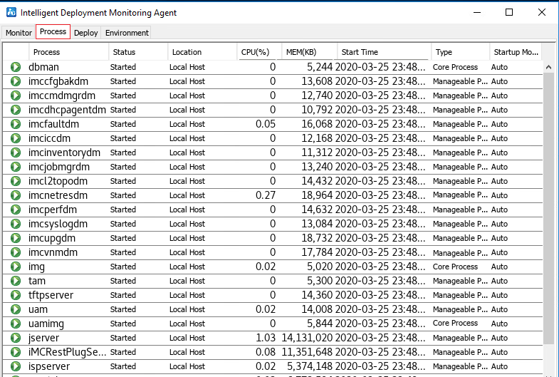
Figure 18 IMC component deployment
Example: Deploying the EAD gateway in a network
Network configuration
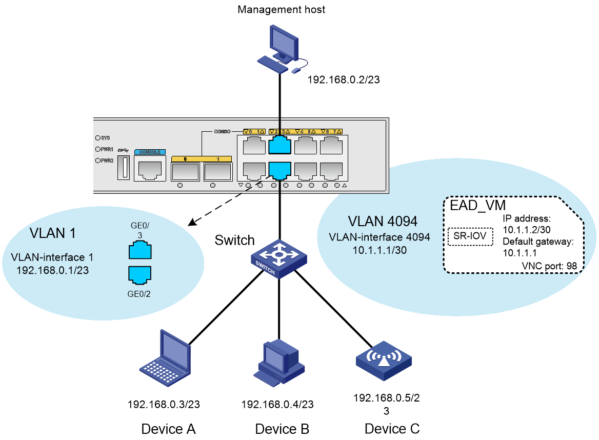
As shown in Figure 19, configure the EAD gateway to control the access behaviors of Device A, Device B, and Device C.
Device A, Device B, and Device C access Layer 2 Ethernet interface GigabitEthernet 0/2 on the EAD gateway through the switch.
The management host accesses Layer 2 Ethernet interface GigabitEthernet 0/3 on the EAD gateway.
Procedure
1. Configure the IP address of the management host as 192.168.0.2/23 and the default gateway as 192.168.0.1. (Details not shown.)
2. Configure the IP addresses of Device A, Device B, and Device C as 192.168.0.3/23, 192.168.0.4/23, and 192.168.0.5/23, respectively. Configure their default gateway as 192.168.0.1. (Details not shown.)
Verifying the configuration
1. Verify that the management host can ping the VM on the EAD gateway. (Details not shown.)
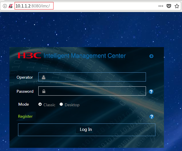
2. Verify that you can log in to the Web interface of the IMC platform. To log in to the Web interface, enter a string in the VM IP address:port number/imc format in the address bar of the Web browser, as shown in Figure 20.
Figure 20 Logging in to the Web interface of the IMC platform
Configuring RAID
About RAID
Redundant Array of Independent Disks (RAID) ensures data reliability and speeds up data reading and writing by storing data in multiple hard disks.
By default, the EAD gateway is built with dual SIC-M2-SATA drives and the drives have been configured to operate in RAID 1 mode. The drive name of the RAID is md0. No manual configuration is required. If reconfiguring the RAID is required, you must follow the restrictions and guidelines in this section.
Restrictions and guidelines for RAID configuration
VM EAD_VM is installed in the root directory of RAID md0. Perform the tasks in this section with caution. If data on RAID md0 is cleared, the VM is removed from the EAD gateway. In this situation, you must redeploy the VM on the EAD gateway.
Configuring RAID
Partitioning the hard disks and modifying the file system format
About this task
On the EAD gateway, only SIC slot 1 and slot 2 support inserting SIC-M2-SATA drives to create RAID 1. The drive name of the SIC-M2-SATA drive installed in SIC slot 1 is hdb. The drive name of the SIC-M2-SATA drive installed in SIC slot 2 is hdc. Before creating a RAID, you must ensure that the SIC-M2-SATA drives in SIC slot 1 and slot 2 each have only one partition and the file system format is EXT4. To partition SIC-M2-SATA drives and set their file system format to EXT4, perform this task.
Restrictions and guidelines
The partition and file system format modification operations will delete all data from an SIC-M2-SATA drive.
Procedure
1. In user view, set the number of partitions to 1 for hard disks hdb and hdc.
<H3C> fdisk hdb: 1
<H3C> fdisk hdc: 1
2. Set the file system format to EXT4 for hard disks hdb0 and hdc0.
<H3C> format hdb0: ext4
<H3C> format hdc0: ext4
Creating a RAID
Restrictions and guidelines
On the EAD gateway, all data on the SIC-M2-SATA drives in SIC slot 1 and slot 2 will be cleared after the RAID that contains the drives is created. The drive name of the RAID on the EAD gateway is md0.
Procedure
1. Enter RAID view.
<H3C> system-view
[H3C] raid
[H3C-raid]
2. Create RAID 1.
[H3C-raid] create raid level 1
Restoring a RAID
About this task
If one of the member SIC-M2-SATA drives in RAID 1 is damaged, you can replace the damaged drive with a new drive to restore the RAID.
Restrictions and guidelines
Before removing the damaged SIC-M2-SATA drive, make sure the RAID is in synchronization completion state (Done). You can use the display raid status command to display the RAID synchronization status.
Before removing the damaged SIC-M2-SATA drive, you must press the remove button and wait for the button light to go out.
Make sure the new SIC-M2-SATA drive has only one partition and the file system format is EXT4.
This task will clear all data from the new SIC-M2-SATA drive.
Procedure
1. Enter RAID view.
<H3C> system-view
[H3C] raid
[H3C-raid]
2. Restore RAID md0.
[H3C-raid] restore raid md0
Removing a RAID
Restrictions and guidelines
Removing a RAID also clears all data from the member SIC-M2-SATA drives of the RAID.
Procedure
1. Enter RAID view.
<H3C> system-view
[H3C] raid
[H3C-raid]
2. Remove RAID 1.
[H3C-raid] remove raid md0
Displaying RAID status information
# Display RAID status information.
<H3C> display raid status
Name Level Status Disks Resync Size(GB)
--------------------------------------------------------------------
md0 raid1 active hdb0[0]hdc0[1] Done 447
Managing VMs
The built-in VM on the EAD gateway is installed in the root directory of RAID md0. The file saving path and hard disk path in the following examples both use the root directory of RAID md0. If external hard disk hda0 is inserted into the EAD gateway, you can specify a directory on md0 or hda0 to save hard disk files and other files.
Starting the VM
1. Enter VMM view.
<H3C> system-view
[H3C] vmm
2. Start VM EAD_VM.
[H3C-vmm] start vm EAD_VM
Stopping the VM
About this task
Stopping the VM uses less than 6 minutes. If the VM cannot be correctly stopped, you must use the stop command with the force keyword to forcibly stop the VM.
Procedure
1. Enter VMM view.
<H3C> system-view
[H3C] vmm
2. Stop VM EAD_VM.
[H3C-vmm] stop vm EAD_VM
Configuring VM auto-start
Restrictions and guidelines
If you enable or disable VM auto-start when the VM is started, the configuration will take effect after you restart the VM.
If you enable or disable VM auto-start when the VM is stopped, the configuration will take effect after you start the VM.
Procedure
1. Enter VMM view.
<H3C> system-view
[H3C] vmm
2. Enable VM auto-start on VM EAD_VM.
[H3C-vmm] autostart vm EAD_VM
3. Disable VM auto-start on VM EAD_VM.
[H3C-vmm] undo autostart vm EAD_VM
Backing up the VM
About this task
Perform this task to back up the VM after the VM is stopped. The backup file is a .vmb file.
You can use a .vmb file to restore the VM when the VM fails.
Procedure
1. Enter VMM view.
<H3C> system-view
[H3C] vmm
2. Back up VM EAD_VM to file md0:/EAD_VM.vmb.
[H3C-vmm] backup vm EAD_VM md0:/EAD_VM.vmb
Restoring the VM
About this task
Perform this task to restore the VM by using a .vmb backup file.
Procedure
1. Enter VMM view.
<H3C> system-view
[H3C] vmm
2. Restore the VM from file md0:/EAD_VM.vmb.
[H3C-vmm] restore pakagepath md0:/EAD_VM.vmb
Exporting the VM to a .pkg file
About this task
Perform this task to export the VM to a .pkg file after the VM is stopped. You can use the .pkg file to deploy the VM on another EAD gateway or use the .pkg file to redeploy the VM on the current EAD gateway.
Procedure
1. Enter VMM view.
<H3C> system-view
[H3C] vmm
2. Export the VM to file md0:/EAD_VM.pkg.
[H3C-vmm] export vm EAD_VM md0:/EAD_VM.pkg
Uninstalling the VM
Restrictions and guidelines
Perform this task to uninstall the VM after the VM is stopped.
Procedure
1. Enter VMM view.
<H3C> system-view
[H3C] vmm
2. Uninstall VM EAD_VM.
[H3C-vmm] uninstall vm EAD_VM
Adding a disk to the VM
Restrictions and guidelines
Before you add a disk to the VM, you must create the disk.
If you add the disk to the VM when the VM is started, you must restart the VM for the add operation to take effect.
If you add the disk to the VM when the VM is stopped, you must start the VM for the add operation to take effect.
Procedure
1. Enter VMM view.
<H3C> system-view
[H3C] vmm
2. Create a VM disk.
create-disk disk-file size size format { raw | qcow2 }
3. Add the disk to the VM.
add disk vm vm-name format { raw | qcow2 } disk-file path-file disk-bus { ide | virtio }
For example:
# Enter VMM view.
<H3C> system-view
[H3C] vmm
# Create a disk. The disk file path is md0:/EAD_VM.qcow, the size is 30 GB, and the format is QCOW2.
[H3C-vmm] create-disk md0:/EAD_VM.qcow size 30 format qcow2
# Add the disk to VM EAD_VM.
[H3C-vmm] add disk vm EAD_VM format qcow2 disk-file md0:/EAD_VM.qcow disk-bus ide
Configuring VMs
For more information about configuring hard disks, vNICs, memory, vCPUs, and other parameters for the VM and the related commands, see the following manuals:
· VM configuration in Virtual Technologies Configuration Guide of H3C MSR810[2600][3600] Routers Configuration Guides.
· VM commands in Virtual Technologies Command Reference of H3C MSR810[2600][3600] Routers Command References.
Display and maintenance commands for VM management
Execute display commands in any view.
|
Command |
|
|
Display the VM list. |
display vmlist |
|
Display VM disk and CD-ROM information. |
display vmdisklist [ vm vm-name ] |
|
Display detailed VM information. |
display vm [ vm-name ] |
|
Display the number of CPUs allocated to the VM. |
display vcpu-pool |
|
Display VM CPU usage. |
display vmcpu-usage vm vm-name |
|
Display VM memory usage. |
display vmmem-usage vm vm-name |
|
Display SR-IOV NIC information. |
display sriov |
|
Display VM network interface information. |
display vminterface [ vm vm-name ] |
|
Display the VM VNC port number. |
display vncport vm vm-name |
|
Display the bindings between vCPUs and physical CPUs. |
display vmcpupin [ vm vm-name ] |
|
Display VM disk usage information. |
display vmdisk-usage vm vm-name |
|
Display physical NIC information. |
display passthrough |
|
Display the SR-IOV NIC network mode. |
display vm-network-mode |
