- Table of Contents
- Related Documents
-
Strategy Partner :
01-Text
Contents
General safety recommendations
Examining the installation site
Installation tools and accessories
Mounting the device on a workbench
Installing the device in a rack
Device dimensions and rack requirements
Installing the device in a rack
Grounding the device through the grounding terminal on the rack
Grounding the device with a grounding strip
Grounding the device by burying a grounding conductor in the earth ground
Connecting an Ethernet cable to a copper port
Connecting an optical fiber to a fiber port
Connecting the console cable and setting terminal parameters
Setting configuration terminal parameters
Replacing a transceiver module
No display on the configuration terminal
Garbled display on the configuration terminal
No response from the serial console port
Appendix A Chassis views and technical specifications
Appendix C Slot arrangement and interface numbering
Preparing for installation
The H3C MSR3610 router series includes the models in Table 1.
Table 1 H3C MSR3610 router series models
|
Model (on the front panel) |
Product code |
|
H3C MSR3610 Series |
RT-MSR3610-X1 |
|
H3C MSR3610 Series |
RT-MSR3610-X1-DP |
|
H3C MSR3610 Series |
RT-MSR3610-X1-DC |
|
H3C MSR3610 Series |
RT-MSR3610-X1-DP-DC |
Safety recommendations
Safety symbols
When reading this document, note the following symbols:
![]() WARNING means an alert that calls attention to important information that if
not understood or followed can result in personal injury.
WARNING means an alert that calls attention to important information that if
not understood or followed can result in personal injury.
![]() CAUTION means an alert that calls attention to important information that if
not understood or followed can result in data loss, data corruption, or damage
to hardware or software.
CAUTION means an alert that calls attention to important information that if
not understood or followed can result in data loss, data corruption, or damage
to hardware or software.
General safety recommendations
· Keep the chassis and installation tools away from walk areas.
· Make sure the installation site is dry and flat and anti-slip measures are in place.
· Remove all the external cables (including power cords) before moving the chassis.
Electricity safety
· Locate the emergency power-off switch before installation. Shut the power off at once in case accident occurs. Disconnect the power cord of the device if necessary.
· Make sure the device is reliably grounded.
· Do not open or close the chassis cover when the device is powered on.
· Correctly connect the interface cables for the device.
· Use an uninterrupted power supply (UPS).
· Do not work alone when the device has power.
· Always make sure the power has been disconnected during the installation and replacement procedures.
Examining the installation site
The device can only be used indoors. For the device to operate correctly and have a prolonged service time, the installation site must meet the following requirements.
Temperature and humidity
Make sure the temperature and humidity in the equipment room meet the requirements described in Table 2.
· Lasting high relative humidity can cause poor insulation, electricity leakage, mechanical property change of materials, and metal corrosion.
· Lasting low relative humidity can cause washer contraction and ESD and cause problems including loose mounting screws and circuit failure.
· High temperature can accelerate the aging of insulation materials and significantly lower the reliability and lifespan of the device.
Table 2 Temperature and humidity requirements for the equipment room
|
Temperature |
Humidity |
|
·
With a hard disk: ·
Without a hard disk: |
5% to 95% (noncondensing) |
Cleanliness
Dust buildup on the chassis might result in electrostatic adsorption, which causes poor contact of metal components and contact points, especially when indoor relative humidity is low. In the worst case, electrostatic adsorption can cause communication failure.
Table 3 Dust concentration limit in the equipment room
|
Substance |
Concentration limit (particles/m3) |
|
Dust particles |
≤ 3 x 10⁴ (No visible dust on desk in three days) |
|
NOTE: Dust particle diameter ≥ 5 µm |
|
The equipment room must also meet limits on salts, acids, and sulfides to eliminate corrosion and premature aging of components, as shown in Table 4.
Table 4 Harmful gas limits in the equipment room
|
Gas |
Max. (mg/m3) |
|
SO2 |
0.2 |
|
H2S |
0.006 |
|
NH3 |
0.05 |
|
Cl2 |
0.01 |
Cooling system
The device uses left to right airflow for heat dissipation.
Figure 1 Airflow through the device
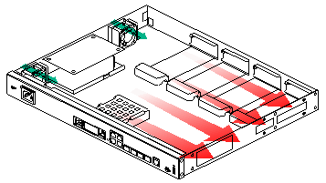
To ensure good ventilation, follow these guidelines:
· The air inlet and outlet vents are not blocked, and a minimum of 10 cm (3.94 in) of clearance is reserved around the chassis.
· The installation site has a good cooling system.
ESD prevention
|
|
CAUTION: Check the resistance of the ESD wrist strap for safety. The resistance reading should be in the range of 1 to 10 megohm (Mohm) between human body and the ground. |
To prevent electrostatic discharge (ESD), follow these guidelines:
· Make sure the device and the floor are reliably grounded.
· Take dust-proof measures for the equipment room.
· Maintain the humidity and temperature in the equipment room at the acceptable range.
· Always wear an ESD wrist strap and ESD garment when touching a circuit board or transceiver module.
· Place the removed interface module on an antistatic workbench, with the PCB upward, or put it into an antistatic bag.
· Touch only the edges, instead of electronic components when you observe or move an interface module.
No ESD wrist strap is provided with the device. Prepare an ESD wrist strap yourself.
To attach an ESD wrist strap:
1. Wear the wrist strap on your wrist.
2. Lock the wrist strap tight around your wrist to keep good contact with the skin.
3. Attach the alligator clip of the strap to the grounding screw on the device.
EMI
All electromagnetic interference (EMI) sources, from outside or inside of the device and application system, adversely affect the device in the following ways:
· A conduction pattern of capacitance coupling.
· Inductance coupling.
· Electromagnetic wave radiation.
· Common impedance (including the grounding system) coupling.
To prevent EMI, use the following guidelines:
· Take effective measures to filter interference from the power grid.
· Keep the device far away from radio transmitting stations, radar stations, and high-frequency devices.
· Use electromagnetic shielding, for example, shielded interface cables, when necessary.
· To prevent signal ports from getting damaged by overvoltage or overcurrent caused by lightning strikes, route interface cables only indoors.
Lightning protection
To enhance lightning protection for the device, follow these guidelines:
· Make sure the device is reliably grounded.
· Make sure the AC power outlet is reliably grounded.
· Install a lightning protector at the power input end.
· Install a lighting protector at the input end of signal cables routed from outdoors, for example, E1/T1 cable.
Rack requirements
To mount the device in a rack, make sure the rack meets the following requirements:
· The rack has a good cooling system.
· The rack is sturdy enough to support the device and its accessories.
· The rack has sufficient space to accommodate the device. After you install the device in the rack, there is enough clearance at two sides of the device for heat dissipation.
· A minimum of 0.8 m (2.62 ft) of clearance is reserved between the rack and walls or other devices for heat dissipation and maintenance.
· The headroom in the equipment room is not less than 3 m (9.84 ft).
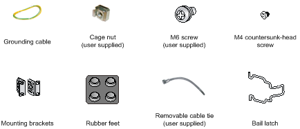
Installation tools and accessories
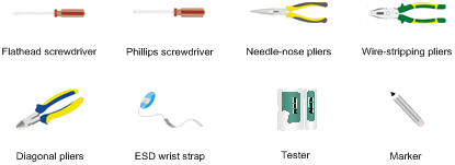
Figure 3 Installation accessories
Pre-installation checklist
Table 5 Pre-installation checklist
|
Item |
Requirements |
Result |
|
|
Installation site |
Ventilation |
· A minimum clearance of 10 cm (3.9 in) is reserved around the air inlet and outlet vents. · The installation site has a good ventilation system. |
|
|
Temperature |
With a hard disk: 5°C to 40°C (41°F to 104°F) Without a hard disk: 0°C to 45°C (32°F to 113°F). |
|
|
|
Relative humidity |
5% to 95% (noncondensing). |
|
|
|
Cleanliness |
· Dust concentration ≤ 3 x 10⁴ particles/m3. · No visible dust on desk within three days. |
|
|
|
ESD prevention |
· The device and floor are reliably grounded. · Dust-proof measures are taken in the equipment room. · Humidity and temperature are maintained at the acceptable range. · An ESD wrist strap and ESD garment are available. · An anti-static workbench and anti-static bags are available. |
|
|
|
EMI prevention |
· Effective measures are taken for filtering interference from the power grid. · The protection ground of the device is away from the grounding facility of power equipment or lightning protection grounding facility. · The device is far away from radio transmitting stations, radar stations, and high-frequency devices. · Electromagnetic shielding, for example, shielded interface cables, is used as required. |
|
|
|
Lightning protection |
· The device is reliably grounded. · The AC power receptacle is reliably grounded. · (Optional.) Port lightning protectors are available. · (Optional.) Power lightning protectors are available. · (Optional.) Signal cable lightning protectors are available. |
|
|
|
Electricity safety |
· A UPS is available. · The power-off switch in the equipment room is identified and accessible so that the power can be immediately shut off when an accident occurs. |
|
|
|
Workbench |
· The workbench is stable. · The workbench is reliably grounded. |
|
|
|
Rack-mounting requirements |
· The rack has a good ventilation system. · The rack is sturdy and can support the device and its accessories. · The rack has a size that can accommodate the device. · A minimum of 0.8 m (2.62 ft) of clearance is reserved between the rack and walls or other devices. |
|
|
|
Safety precautions |
· The device is far away from any sources of heat or moisture. · The emergency power switch in the equipment room is identified and accessible. |
|
|
|
Tools |
· Installation accessories supplied with the device are available. · User supplied tools are available. |
|
|
|
Reference |
· Documents shipped with the device are available. · Online documents are available. |
|
|
Installing the device
|
|
WARNING! To avoid injury, do not touch bare wires, terminals, or parts with high-voltage hazard signs. |
|
|
IMPORTANT: · The barcode on the device chassis contains product information that must be provided to local sales agent when you return a faulty device for repair. · Keep the tamper-proof seal on a mounting screw on the chassis cover intact, and if you want to open the chassis, contact H3C for permission. Otherwise, H3C shall not be liable for any consequence. |
Installation prerequisites
· You have read "Preparing for installation" carefully.
· All requirements in "Preparing for installation" are met.
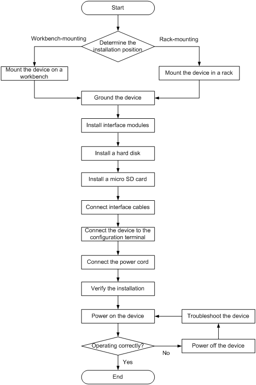
Installation flowchart
You can install the device on a workbench or in a rack.
Determine the installation method according to the installation environment. Follow the installation flowchart shown in Figure 4 to install the device.
Figure 4 Installation flowchart
Mounting the device on a workbench
|
|
IMPORTANT: · Make sure the workbench is clean, stable, and reliably grounded. · Maintain a minimum clearance of 10 cm (3.9 in) around the device for heat dissipation. · Do not place heavy objects on the device. |
To mount the device on a workbench:
1. Place the device upside down on the workbench and attach the rubber feet to the four round holes in the chassis bottom.
2. Place the device upside up on the workbench. Make sure the rubber feet stand securely on the workbench.
Figure 5 Attaching rubber feet to the device
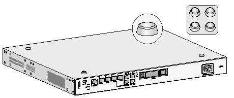
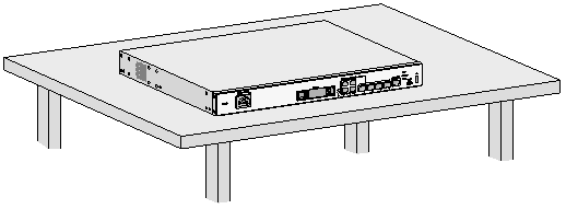
Figure 6 Mounting the device on a workbench
Installing the device in a rack
Device dimensions and rack requirements
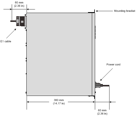
Table 6 Device dimensions and rack requirements
|
Chassis dimensions |
Rack requirements |
|
· Height—43.6 mm (1.72 in)/1 RU · Width—440 mm (17.32 in) · Depth—480 mm (18.90 in) ¡ 360 mm (14.17 in) for the chassis ¡ 60 mm (2.36 in) for connecting AC or DC power cord at the front ¡ 60 mm (2.36 in) for connecting the E1 cable at the rear |
· A minimum of 0.6 m (1.97 ft) in depth (recommended) · A minimum of 80 mm (3.15 in) between the front rack post and the front door. · A minimum of 420 mm (16.54 in) between the front rack post and the rear door. |
Installing the device in a rack
|
|
CAUTION: The mounting brackets can support only the weight of the device. Do not place objects on the device. |
To install the device in a rack:
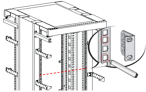
1. Use a mounting bracket to mark the cage nut installation holes in the front rack posts, as shown in Figure 8.
Make sure the cage nut installation holes on the front rack posts are on a horizontal line.
Figure 8 Marking cage nut installation holes
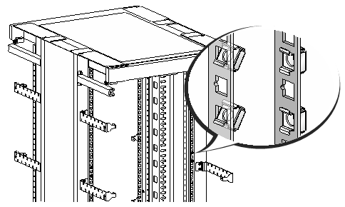
2. Install cage nuts, as shown in Figure 9.
a. Insert one ear of a cage nut into the marked installation hole.
b. Use a flathead screwdriver to push another ear into the hole.
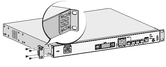
3. Attach mounting brackets to both sides of the device, as shown in Figure 10.
Figure 10 Attaching mounting brackets to the device
4. Put the device in the rack. Use M6 screws to attach the mounting brackets on the device to the front rack posts, as shown in Figure 11.
Figure 11 Securing the device to the rack
Grounding the device
|
|
CAUTION: · Correctly connecting the grounding cable is crucial to lightning protection and EMI protection. When you install and use the device, first ground the device reliably. · Ensure a minimum resistance of 5 ohms between the device and the ground. |
A grounding cable is provided with the device. You can use the grounding cable to ground the device.
Grounding the device through the grounding terminal on the rack
|
|
IMPORTANT: Make sure the rack is reliably grounded before grounding the device. |
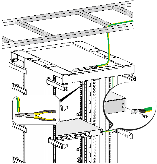
To ground the device through the grounding terminal on the rack:
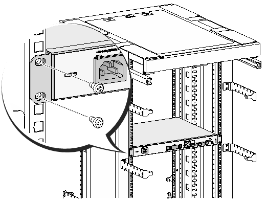
1. Remove the grounding screw from the grounding hole in the rear panel of the chassis.
2. Use the grounding screw to attach the ring terminal of the grounding cable to the grounding hole. See Figure 12.
3. Remove the hex nut from a grounding post on the grounding terminal of the rack.
4. Use needle-nose pliers to bend a hook at the other end of the grounding cable. Attach the hook to the grounding post and use the hex nut to secure the hook to the post. See Figure 13.
Figure 12 Connecting the grounding cable to the device
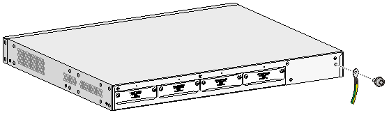
Figure 13 Grounding the device through the grounding terminal on the rack
Grounding the device with a grounding strip
If a grounding strip is available at the installation site, connect the grounding cable to the grounding strip.
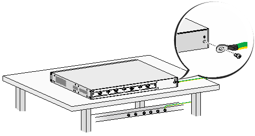
To ground the device with a grounding strip:
1. Remove the grounding screw from the grounding hole in the rear panel of the chassis.
2. Use the grounding screw to attach the ring terminal of the grounding cable to the grounding hole.
3. Remove the hex nut from a grounding post on a grounding strip.
4. Use needle-nose pliers to bend a hook at the other end of the grounding cable. Attach the hook to the grounding post and use the hex nut to secure the hook to the post.
Figure 14 Grounding the device with a grounding strip
Grounding the device by burying a grounding conductor in the earth ground
If the installation site does not have any grounding strips, but earth ground is available, hammer a 0.5 m (1.64 ft) or longer angle iron or steel tube into the earth ground to serve as a grounding conductor. The steel tube must be zinc-coated. Weld the yellow-green grounding cable to the angel iron or steel tube and treat the joint for corrosion protection.
Installing interface modules
Installing a SIC
|
|
CAUTION: SICs are not hot swappable. Make sure the device is powered off before installing a SIC. |
To install a SIC:
1. Use a Phillips screwdriver to remove the fastening screws on the filler panel and remove the filler panel. See Figure 15.
2. Push the SIC slowly into the slot along the guide rails until it makes close contact with the backplane of the device. See Figure 16.
3. Fasten the captive screws on the SIC.
Figure 15 Removing the filler panel
Installing a hard disk
Only the MSR3610-X1 and MSR3610-X1-DP support a hard disk. No hard disk is provided with the device. To user a hard disk, purchase one from H3C.
To install a hard disk:
1. Remove the filler panel from the hard disk slot, as shown in Figure 17.
2. Push the hard disk slowly into the slot along the guide rails, as shown in Figure 18.
Figure 17 Removing the filler panel from the hard disk slot
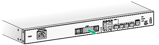
Figure 18 Installing the hard disk
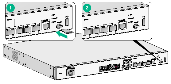
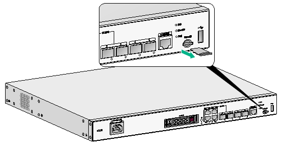
Installing a micro SD card
No micro SD card is provided with the device. To use a micro SD card, purchase one yourself.
When you install a micro SD card, do not use excessive force to avoid damaging the micro SD card slot. Insert the micro SD card into the slot along the guide rails.
Figure 19 Installing a micro SD card
Connecting interface cables
Connect cables to the interfaces on the device before powering on the device. This section describes the procedures for installing Ethernet interface cables.
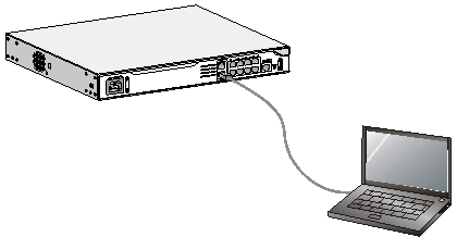
Connecting an Ethernet cable to a copper port
1. Connect one end of the Ethernet cable to the copper port on the device. Connect the other end of the cable to the copper port on the peer device.
The fixed copper ports on the device are MDI/MDIX autosensing. You can use straight-through or crossover network cables to connect the ports.
2. Examine the port LED on the device to verify that the cable is connected correctly. For more information about the LEDs, see "Figure 20."
Figure 20 Connecting the device to a terminal
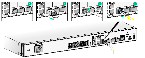
Connecting an optical fiber to a fiber port
|
|
WARNING! Do not stare into any fiber port when you connect an optical fiber. The laser light emitted from the optical fiber might hurt your eyes. |
Follow these guidelines when you connect a fiber cable:
· Never bend or curve a fiber when connecting it.
· Make sure the Tx and Rx ports are connected correctly.
· Keep the fiber end clean.
· Be sure to install the dust cover if the fiber port is not connected to a fiber connector.
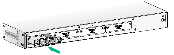
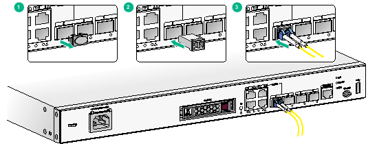
To connect an optical fiber:
1. Remove the dust plug from the fiber port.
2. Align the transceiver module end without a pull latch to the fiber port. Correctly orient the transceiver module and insert it into the fiber port.
3. Identify the Rx and Tx ports on the transceiver module. Use the optical fiber to connect the Rx port of the transceiver module to the Tx port of the peer device and the Tx port to the Rx port.
4. Examine the port LED on the device to verify that the optical fiber is connected correctly. For more information, see "Appendix B LEDs."
Figure 21 Connecting an optical fiber to a fiber port
Connecting the console cable and setting terminal parameters
To access the device for the first time, use a console cable to connect the console port on the device.
Connecting the console cable
|
|
CAUTION: The serial ports on PCs do not support hot swapping. To connect a PC to an operating device, first connect the PC end. To disconnect a PC from an operating device, first disconnect the device end. |
To connect the console cable:
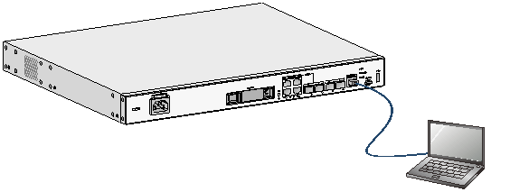
1. Select a configuration terminal, which can be an ASCII terminal with an RS232 serial port or a PC. (A PC is more commonly used.)
2. Connect the DB-9 connector (female) of the console cable to the RS-232 serial port on the configuration terminal and the RJ-45 connector to the console port of the device.
Figure 22 Connecting the console cable
|
|
NOTE: If the PC does not have a console port but a USB port, use a USB-to-serial adapter to connect the USB port to the console cable. Make sure USB-to-serial drive has been installed on the PC. |
Setting configuration terminal parameters
To configure and manage the device through the console port, you must run a terminal emulator program, TeraTermPro or PuTTY, on your PC. You can use the emulator program to connect a network device, a Telnet site, or an SSH site. For more information about the terminal emulator programs, see the user guides for these programs.
The following are the required terminal settings:
· Baud rate—9600.
· Data bits—8.
· Stop bits—1.
· Parity—None.
· Flow control—None.
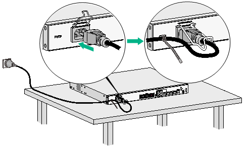
Connecting the AC power cord
1. Make sure the device is reliably grounded.
3. Connect the other end of the power cord to the AC power source.
The power cord in Figure 23 is for illustration only.
Figure 23 Connecting the AC power cord
Connecting the DC power cord
|
|
WARNING! Pay attention to the mark on the power cord to avoid connection errors. |
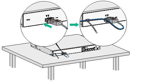
To connect the DC power cord:
1. Make sure the device is reliably grounded.
2. Loosen the fastening screws on the protection cover over the DC power receptacle on the device and remove the cover.
3. Connect one end of the DC power cord supplied with the device to the DC receptacle on the device. Connect the two wires of the other end to the DC power source, the black wire to the positive terminal and the blue wire to the negative terminal.
Figure 24 Connecting the DC power cord
Verifying the installation
Verify the following items before you power on the device:
· There is enough space around the device for heat dissipation.
· The interface modules are installed correctly.
· The device, rack, and power source are reliably grounded.
· The power source is as required by the device.
· The device is connected correctly to the configuration terminal and other devices. The configuration terminal is configured correctly and has been started.
Starting the device
|
|
WARNING! Before powering on the device, locate the switch for the power source so that you can cut off power promptly in case of an emergency. |
To start the device:
1. Verify that the installation and configuration environment is as described in "Verifying the installation."
2. Power on the device.
3. During the booting process, verify the following items:
¡ The LEDs on the front panel are in the states as described in Table 7.
Table 7 LED states when the device is operating correctly
|
LED |
State |
Description |
|
PWR |
Steady green |
The power system is operating correctly. |
|
SYS |
Flashing green slowly |
The device system is operating correctly. |
¡ The configuration terminal displays information correctly. Observe the information displayed on the configuration terminal.
The device first initializes its memory at startup. Then it runs BootWare.
System is starting...
Press Ctrl+D to access BASIC-BOOTWARE MENU...
Press Ctrl+T to start heavy memory test.
Booting Normal Extended BootWare
The Extended BootWare is self-decompressing....Done.
****************************************************************************
* *
* H3C MSR3610 BootWare, Version 1.01 *
* *
****************************************************************************
Copyright (c) 2004-2017 New H3C Technologies Co., Ltd.
Compiled Date : Apr 12 2016
CPU ID : 0x11
Memory Type : DDR3 SDRAM
Memory Size : 2048MB
Flash Size : 8MB
Nandflash Size : 512MB
CPLD Version : 129.0
PCB Version : 2.0
BootWare Validating...
Press Ctrl+B to access EXTENDED-BOOTWARE MENU...
Loading the main image files...
Loading file flash:/msr36x1-cmw710-system-a0408p05.bin......................
..........................Done.
Loading file flash:/msr36x1-cmw710-security-a0408p05.bin...Done.
Loading file flash:/msr36x1-cmw710-voice-a0408p05.bin....Done.
Loading file flash:/msr36x1-cmw710-data-a0408p05.bin......Done.
Loading file flash:/msr36x1-cmw710-boot-a0408p05.bin..........Done.
Image file flash:/msr36x1-cmw710-boot-a0408p05.bin is self-decompressing....
.Done.
System image is starting...
Line aux0 is available.
Press ENTER to get started.
Press Enter. The device is ready to configure when you see the following prompt:
<Sysname>
4. Configure basic settings for the device.
For information about the configuration procedure, see the configuration guide for the device.
Replacement procedure
|
|
IMPORTANT: · The barcode on the device chassis contains product information that must be provided to local sales agent before you return a faulty device for service. · Keep the tamper-proof seal on a mounting screw on the chassis cover intact, and if you want to open the chassis, contact H3C for permission. Otherwise, H3C shall not be liable for any consequence. |
|
|
CAUTION: Always wear an ESD wrist strap when you replace a component on the device. |
Replacing a SIC
|
|
CAUTION: SICs are not hot swappable. Make sure the device is powered off when you replace a SIC. |
To replace a SIC:
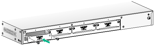
1. Loosen the captive screws on the SIC.
2. Pull the SIC slowly out of the slot along the guide rails.
3. Install a new SIC in the slot. For information about the installation procedure, see "Installing the device."
4. If you are not to install a new SIC, install a filler panel in the slot and fasten the screws on the filler panel. See Figure 26.
Figure 25 Removing the SIC
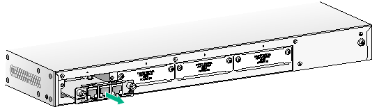
Figure 26 Installing the filler panel
Replacing a hard disk
|
|
CAUTION: · To remove the hard disk when the device is operating, press the HD button for over five seconds. When the LED for the hard disk turns off, you can remove the hard disk. You can also use the umount command to unmount the file system and remove the hard disk after the unmount operation succeeds. · After you remove the hard disk, wait 10 seconds or more before installing a new one to avoid file system corruption. If the file system is corrupted, use the mount command to mount the file system. |
To replace a hard disk:
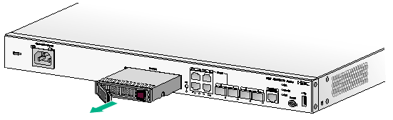
1. Press the button on the right side of the hard disk tray panel to release the ejector lever of the tray.
2. Hold the ejector lever to pull the disk out of the slot.
3. Install a new hard disk in the slot. For information about the installation procedure, see "Installing the device."
4. If you are not to install a new hard disk, install a filler panel in the slot.
Figure 27 Removing the hard disk (1)
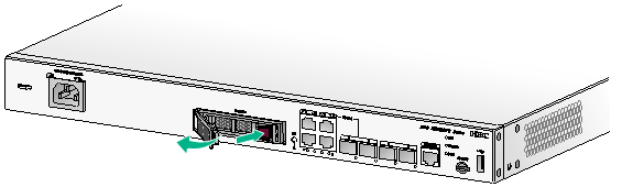
Figure 28 Installing the hard disk (2)
Replacing a micro SD card
|
|
CAUTION: · A micro SD card is not hot swappable. If the micro SD card needs to be replaced when the device is operating, execute the umount command before the replacement. · Do not use excessive force when you replace a micro SD card to avoid damaging the micro SD card slot. |
To replace a micro SD card:
1. Pull the micro SD card out of the slot along the guide rails.
Keep the micro SD card secure.
2. Install a new micro SD card in the slot. For more information about the installation procedure, see "Installing the device."
Figure 29 Removing the micro SD card
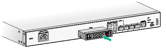
Replacing a transceiver module
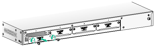
1. Remove the cable from the transceiver module.
2. Use forceps to release the pull latch on the transceiver module.
3. Pinching the pull latch by using forceps, pull out the transceiver module slowly.
4. Insert a dust cover in the fiber port.
5. Keep secure the removed transceiver module.
Figure 30 Removing a transceiver module
Troubleshooting
|
|
IMPORTANT: · The barcode on the device chassis contains product information that must be provided to local sales agent when you return a faulty device for repair. · Keep the tamper-proof seal on a mounting screw on the chassis cover intact, and if you want to open the chassis, contact H3C for permission. Otherwise, H3C shall not be liable for any consequence. |
Power supply failure
Symptom
The device cannot be powered on and the PWR LED on the front panel is off.
Solution
To resolve the problem:
1. Power off the device.
2. Verify that the device is connected to the power source correctly.
3. Verify that the power source is operating correctly.
4. Verify that the power cord is in good condition.
5. If the problem persists, contact H3C Support.
Fan tray failure
Symptom
After the device starts up, the configuration terminal displays the following information:
%Jun 22 16:11:37:485 2015 H3C DEV/4/FAN FAILED:
Fan 1 failed.
Solution
To resolve the problem:
1. Examine whether any obstacle enters the chassis and blocks the fans. Remove the object, if any, from the chassis.
2. Power-cycle the device.
3. If the problem persists, contact H3C Support.
No display on the configuration terminal
Symptom
The configuration terminal does not have display when the device is powered on.
Solution
To resolve the problem:
1. Verify that the power system is operating correctly.
2. Verify that the console cable is connected correctly and the connected serial port is the same as the port configured on the terminal.
3. Verify that the terminal is configured correctly:
¡ Baud rate—9,600.
¡ Data bits—8.
¡ Parity—None.
¡ Stop bits—1.
¡ Flow control—None.
¡ Emulation—VT100.
4. Verify that the console cable is in good condition.
5. If the problem persists, contact H3C Support.
Garbled display on the configuration terminal
Symptom
The configuration terminal has garbled display when the device is powered on.
Solution
To resolve the problem:
1. Verify that the Data bits field is set to 8 for the terminal. If the Data bits field is set to 5 or 6, the terminal displays garbled characters.
2. If the problem persists, contact H3C Support.
No response from the serial console port
Symptom
The console port on the device is connected to a serial port on a configuration terminal. No boot information is displayed on the configuration terminal when the device starts up or restarts up.
Solution
To resolve the problem:
1. Verify that the serial console cable is in good condition.
2. Verify that the port settings are correct.
3. If the problem persists, contact H3C Support.
Interface module failure
Symptom
An interface module is installed in the device, but the LED for the interface module is not on after the device is powered on.
Solution
To resolve the problem:
1. Verify that the interface module has good contact with the backplane of the device.
2. Verify that the device supports the interface module.
3. Verify that the interface module is installed in the correct slot.
4. Verify that a correct interface cable is used.
5. Verify that the interface cable is connected correctly.
6. If the problem persists, contact H3C Support.
Appendix A Chassis views and technical specifications
Chassis views
The figures in this section are for illustration only.
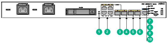
MSR3610-X1
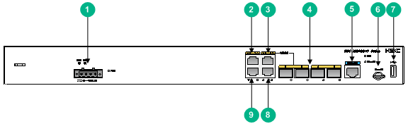
Figure 31 Front panel
|
(2) Hard disk slot |
(3) HD button |
|
|
(4) Gigabit Ethernet port GE1 |
(5) Gigabit Ethernet port GE3 |
(6) SFP fiber ports 2 to 5 |
|
(7) Console port |
(8) Micro SD card slot |
(9) USB port |
|
(10) Gigabit Ethernet port GE2 |
(11) Gigabit Ethernet port GE0 |
|
Figure 32 Rear panel
|
(1) SIC slot 4 |
(2) SIC slot 3 |
(3) SIC slot 2 |
|
(4) SIC slot 1 |
(5) Grounding terminal |
|
MSR3610-X1-DP
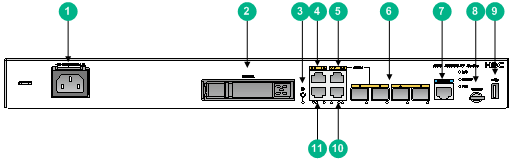
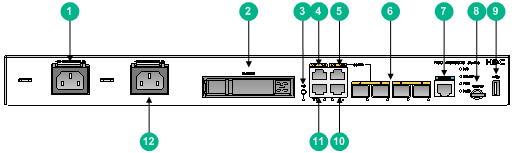
Figure 33 Front panel
|
(1) AC power receptacle (PWR1) |
(2) Hard disk slot |
(3) HD button |
|
(4) Gigabit Ethernet port GE1 |
(5) Gigabit Ethernet port GE3 |
(6) SFP ports SFP2 to SFP5 |
|
(7) Console port |
(8) Micro SD card slot |
(9) USB port |
|
(10) Gigabit Ethernet port GE2 |
(11) Gigabit Ethernet port GE0 |
(12) AC power receptacle (PWR2) |
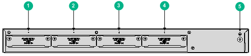
Figure 34 Rear panel
|
(1) SIC slot 4 |
(2) SIC slot 3 |
(3) SIC slot 2 |
|
(4) SIC slot 1 |
(5) Grounding terminal |
|
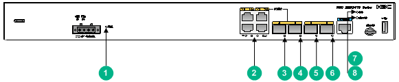
MSR3610-X1-DC
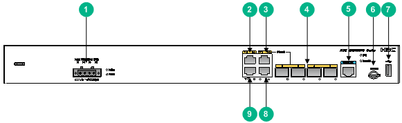
Figure 35 Front panel
|
(1) DC power receptacle |
(2) Gigabit Ethernet port GE1 |
(3) Gigabit Ethernet port GE3 |
|
(4) SFP ports SFP2 to SFP5 |
(5) Console port |
(6) Micro SD card slot |
|
(7) USB port |
(8) Gigabit Ethernet port GE2 |
(9) Gigabit Ethernet port GE0 |
Figure 36 Rear panel
|
(1) SIC slot 4 |
(2) SIC slot 3 |
(3) SIC slot 2 |
|
(4) SIC slot 1 |
(5) Grounding terminal |
|
MSR3610-X1-DP-DC
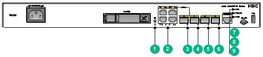
Figure 37 Front panel
|
(1) DC power receptacle |
(2) Gigabit Ethernet port GE1 |
(3) Gigabit Ethernet port GE3 |
|
(4) SFP ports SFP2 to SFP5 |
(5) Console port |
(6) Micro SD card slot |
|
(7) USB port |
(8) Gigabit Ethernet port GE2 |
(9) Gigabit Ethernet port GE0 |
Figure 38 Rear panel
|
(1) SIC slot 4 |
(2) SIC slot 3 |
(3) SIC slot 2 |
|
(4) SIC slot 1 |
(5) Grounding terminal |
|
Technical specifications
Table 8 Technical specifications
|
Item |
MSR2600-10-X1 |
MSR3610-X1-DP |
MSR3610-X1-DC |
MSR3610-X1-DP-DC |
|
Console port |
1 |
1 |
1 |
1 |
|
USB port |
1 |
1 |
1 |
1 |
|
GE port |
4, including two copper combo ports |
4, including two copper combo ports |
4, including two copper combo ports |
4, including two copper combo ports |
|
SFP port |
2 |
2 |
2 |
2 |
|
Memory |
2GB DDR3 |
2GB DDR3 |
2GB DDR3 |
2GB DDR3 |
|
Flash |
512 MB |
512 MB |
512 MB |
512 MB |
|
Hard disk |
1 (2.5 inch, SATA connectors) |
1 (2.5 inch, SATA connectors) |
N/A |
N/A |
|
Micro SD card slot |
1 |
1 |
1 |
1 |
|
SIC slot |
4 |
4 |
4 |
4 |
|
Dimensions (H × W × D) (excluding rubber feet and mounting brackets) |
43.6 × 440 × 360 mm (1.72 × 17.32 × 14.17 in) |
43.6 × 440× 360 mm (1.72 × 17.32 × 14.17 in) |
43.6 × 440× 360 mm (1.72 × 17.32 × 14.17 in) |
43.6 × 440× 360 mm (1.72 × 17.32 × 14.17 in) |
|
AC power input |
Single AC input |
Dual AC inputs |
N/A |
N/A |
|
DC power input |
N/A |
N/A |
Single DC input |
Dual DC inputs |
|
Rated AC/DC voltage |
100 VAC to 240 VAC @ 50 to 60 Hz |
100 VAC to 240 VAC @ 50 to 60 Hz |
–48 VDC to –60 VDC |
–48 VDC to –60 VDC |
|
Rated AC/DC power |
54 W |
54 W |
66 W |
66 W |
|
Operating temperature |
· Without a hard disk: 0°C to 45°C (32°F to 113°F) · With a hard disk: 5°C to 40°C (41°F to 104°F) |
· Without a hard disk: 0°C to 45°C (32°F to 113°F) · With a hard disk: 5°C to 40°C (41°F to 104°F) |
0°C to 45°C (32°F to 113°F) |
0°C to 45°C (32°F to 113°F) |
|
Relative humidity (non-condensing) |
5% to 95% |
5% to 95% |
5% to 95% |
5% to 95% |
Appendix B LEDs
MSR3610-X1
Figure 39 MSR3610-X1 LEDs
|
(1) Hard disk LED |
(2) LEDs for Gigabit Ethernet ports GE0 to GE3 |
(3) LED for SFP fiber port SFP2 |
|
(4) LED for SFP fiber port SFP3 |
(5) LED for SFP fiber port SFP4 |
(6) LED for SFP fiber port SFP5 |
|
(7) System status LED (SYS) |
(8) Micro SD card LED (MicroSD) |
(9) Power status LED (PWR) |
MSR3610-X1-DP
Figure 40 MSR3610-X1-DP LEDs
|
(1) Hard disk LED |
(2) LEDs for Gigabit Ethernet ports GE0 to GE3 |
(3) LED for SFP fiber port SFP2 |
|
(4) LED for SFP fiber port SFP3 |
(5) LED for SFP fiber port SFP4 |
(6) LED for SFP fiber port SFP5 |
|
(7) System status LED (SYS) |
(8) Micro SD card LED (MiscroSD) |
(9) Power status LED (PWR1) |
|
(10) Power status LED (PWR2) |
||
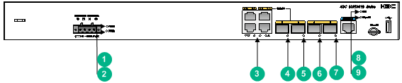
MSR3610-X1-DC
Figure 41 MSR3610-X1-DC LEDs
|
(1) Power status LED (PWR) |
(2) LEDs for Gigabit Ethernet ports GE0 to GE3 |
(3) LED for SFP fiber port SFP2 |
|
(4) LED for SFP fiber port SFP3 |
(5) LED for SFP fiber port SFP4 |
(6) LED for SFP fiber port SFP5 |
|
(7) System status LED (SYS) |
(8) Micro SD card LED (MiscroSD) |
|
MSR3610-X1-DP-DC
Figure 42 MSR3610-X1-DP-DC LEDs
|
(1) Power status LED (PWR1) |
(2) Power status LED (PWR2) |
(3) LEDs for Gigabit Ethernet ports GE0 to GE3 |
|
(4) LED for SFP fiber port SFP2 |
(5) LED for SFP fiber port SFP3 |
(6) LED for SFP fiber port SFP4 |
|
(7) LED for SFP fiber port SFP5 |
(8) System status LED (SYS) |
(9) Micro SD card LED (MiscroSD) |
LED description
|
LED |
Status |
Description |
|
System status LED (SYS) |
Flashing green (1 Hz) |
Comware has started with the configuration file and the device has booted up. |
|
Flashing green (8 Hz) |
The system software image is being copied and decompressed. |
|
|
Steady green |
The SDRAM is performing self-test. |
|
|
Flashing yellow (1 Hz) |
The SDRAM has failed the self-test. |
|
|
Flashing yellow (8 Hz) |
The BootWare extended segment does not exist. |
|
|
Steady yellow |
The system software image does not exist. |
|
|
Off |
No power input, or exceptions have occurred. |
|
|
Flashing yellow at 8 Hz for 5s |
USB flash disk self-configuration succeeded. |
|
|
Flashing yellow at 8 Hz for 10s |
USB flash disk self-configuration failed. |
|
|
Micro SD card LED (MicroSD) |
Green |
The Micro SD card is in position and has passed the test. |
|
Flashing green at 8 Hz |
The system is accessing the Micro SD card and data is being sent and received. |
|
|
Yellow |
The Micro SD card has failed. |
|
|
Off |
No Micro SD card is in position, or the card is not identified. |
|
|
Power status LED (PWR) |
Steady green |
The power system is operating correctly. |
|
Off |
No power is being input. |
|
|
SFP port LED |
Steady green |
A 1000 Mbps link is present. |
|
Flashing green |
Data is being received or transmitted at 1000 Mbps. |
|
|
Steady yellow |
A 10/100 Mbps link is present. |
|
|
Flashing yellow |
Data is being received or transmitted at 10/100 Mbps |
|
|
Off |
No link is present. |
|
|
GE port LED |
Steady green |
A 1000 Mbps link is present. |
|
Flashing green |
Data is being received or transmitted at 1000 Mbps. |
|
|
Steady yellow |
A 10/100 Mbps link is present. |
|
|
Flashing yellow |
Data is being received or transmitted at 10/100 Mbps. |
|
|
Off |
No link is present. |
|
|
Hard disk LED (HD) |
Green |
The hard disk is in position and has passed the test. |
|
Flashing green (8 Hz) |
The system is accessing the hard disk and data is being sent and received. |
|
|
Yellow |
The hard disk has failed. |
|
|
Off |
No hard disk is in position or the hard disk is removed. |
Appendix C Slot arrangement and interface numbering
The device provides SIC slots. The fixed ports on the front panel of the device are in slot 0.
Table 9 Slot arrangement and interface numbering
|
Model |
Slot arrangement |
Interface numbering |
|
MSR3610-X1 |
|
·
In standalone mode: ·
In IRF mode: |
|
MSR3610-X1-DP |
|
|
|
MSR3610-X1-DC |
|
|
|
MSR3610-X1-DP-DC |
|
|
|
|
||
Coperation Event & Solution
- H3C MSR3610-X1 Gigabit Ethernet Integrated Service Gateway Installation Guide-6W100-Text.pdf
