- Table of Contents
-
- 04-Layer 2 - LAN Switching Configuration Guide
- 00-Preface
- 01-MAC address table configuration
- 02-Ethernet link aggregation configuration
- 03-Port isolation configuration
- 04-VLAN configuration
- 05-MVRP configuration
- 06-QinQ configuration
- 07-VLAN mapping configuration
- 08-VLAN termination configuration
- 09-Spanning tree configuration
- 10-LLDP configuration
- 11-Service loopback group configuration
- 12-Loop detection configuration
- Related Documents
-
| Title | Size | Download |
|---|---|---|
| 07-VLAN mapping configuration | 109.76 KB |
VLAN mapping application scenario
Restrictions and guidelines: VLAN mapping configuration
Restriction: Hardware compatibility
Restriction: Feature compatibility
Configuring one-to-one VLAN mapping
Display and maintenance commands for VLAN mapping
Configuring VLAN mapping
About VLAN mapping
VLAN mapping re-marks VLAN traffic with new VLAN IDs.
VLAN mapping application scenario
As shown in Figure 1, one-to-one mapping is used to replace the CVLAN of user packets with an SVLAN. With one-to-one VLAN mapping, packets from the customer network can be transmitted over the service provider network.
Figure 1 Application scenario of one-to-one VLAN mapping

VLAN mapping implementations
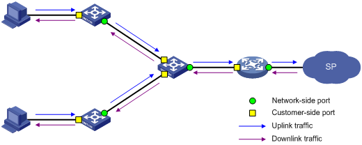
Figure 2 shows a simplified network that illustrates basic VLAN mapping terms.
Basic VLAN mapping terms include the following:
· Uplink traffic—Traffic transmitted from the customer network to the service provider network.
· Downlink traffic—Traffic transmitted from the service provider network to the customer network.
· Network-side port—A port connected to or closer to the service provider network.
· Customer-side port—A port connected to or closer to the customer network.
Figure 2 Basic VLAN mapping terms
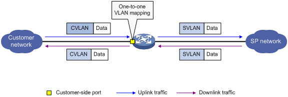
As shown in Figure 3, one-to-one VLAN mapping is implemented on the customer-side port and replaces VLAN tags as follows:
· Replaces the CVLAN with the SVLAN for the uplink traffic.
· Replaces the SVLAN with the CVLAN for the downlink traffic.
Figure 3 One-to-one VLAN mapping implementation
Restrictions and guidelines: VLAN mapping configuration
Restriction: Hardware compatibility
VLAN mapping is supported only on the SPC cards, CSPC cards (except CSPC-GE16XP4L-E, CSPC-GE24L-E, and CSPC-GP24GE8XP2L-E) and CMPE-1104 cards.
Restriction: Feature compatibility
To add or replace VLAN tags for packets, you can configure both VLAN mapping and a QoS policy. The QoS policy takes effect if a configuration conflict occurs. For information about QoS policies, see ACL and QoS Configuration Guide.
Prerequisites
Before you configure VLAN mapping, create original and translated VLANs.
Configuring one-to-one VLAN mapping
About one-to-one VLAN mapping
Configure one-to-one VLAN mapping on the PE (see Figure 1) to isolate traffic of the same service type from different homes.
Procedure
1. Enter system view.
system-view
2. Enter interface view.
¡ Enter Layer 2 Ethernet interface view.
interface interface-type interface-number
¡ Enter Layer 2 aggregate interface view.
interface bridge-aggregation interface-number
3. Set the link type of the port.
port link-type { hybrid | trunk }
By default, the link type of a port is access.
4. Assign the port to the original VLAN and the translated VLAN.
¡ Assign the trunk port to the original VLAN and the translated VLAN.
port trunk permit vlan vlan-id-list
By default, a trunk port is assigned to VLAN 1.
¡ Assign the hybrid port to the original VLAN and the translated VLAN as a tagged member.
port hybrid vlan vlan-id-list tagged
By default, a hybrid port is an untagged member of the VLAN to which the port belongs when its link type is access.
5. Configure a one-to-one VLAN mapping.
vlan mapping vlan-id translated-vlan vlan-id
By default, no VLAN mapping is configured on an interface.
Display and maintenance commands for VLAN mapping
Execute display commands in any view.
|
Task |
Command |
|
Display VLAN mapping information. |
display vlan mapping [ interface interface-type interface-number ] |
VLAN mapping configuration examples
Example: Configuring one-to-one VLAN mapping
Network configuration
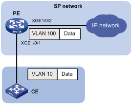
As shown in Figure 4, configure one-to-one VLAN mapping on the PE to map VLAN 10 to VLAN 100, so user packets can be transmitted over the service provider network.
Procedure
1. Configure PE:
# Create the original VLAN and the translated VLAN.
<PE> system-view
[PE] vlan 10
[PE-vlan10] quit
[PE] vlan 100
[PE-vlan100] quit
# Configure customer-side port Ten-GigabitEthernet 1/0/1 as a trunk port.
[PE] interface ten-gigabitethernet 1/0/1
[PE-Ten-GigabitEthernet1/0/1] port link-type trunk
# Assign Ten-GigabitEthernet 1/0/1 to the original VLAN and the translated VLAN.
[PE-Ten-GigabitEthernet1/0/1] port trunk permit vlan 10 100
# Configure one-to-one VLAN mapping on Ten-GigabitEthernet 1/0/1 to map VLAN 10 to VLAN 100.
[PE-Ten-GigabitEthernet1/0/1] vlan mapping 10 translated-vlan 100
[PE-Ten-GigabitEthernet1/0/1] quit
# Configure network-side port Ten-GigabitEthernet 1/0/2 as a trunk port.
[PE] interface ten-gigabitethernet 1/0/2
[PE-Ten-GigabitEthernet1/0/2] port link-type trunk
# Assign Ten-GigabitEthernet 1/0/2 to VLAN 100.
[PE-Ten-GigabitEthernet1/0/2] port trunk permit vlan 100
[PE-Ten-GigabitEthernet1/0/2] quit
Verifying the configuration
# Verify VLAN mapping information on the PE.
[PE] display vlan mapping
Interface Ten-GigabitEthernet1/0/1:
Outer VLAN Inner VLAN Translated Outer VLAN Translated Inner VLAN
10 N/A 100 N/A