- Table of Contents
-
- 03-Layer 2-LAN Switching Configuration Guide
- 00-Preface
- 01-Ethernet interface configuration
- 02-Loopback, null, and inloopback interface configuration
- 03-Bulk interface configuration
- 04-MAC address table configuration
- 05-Ethernet link aggregation configuration
- 06-Port isolation configuration
- 07-Spanning tree configuration
- 08-Loop detection configuration
- 09-VLAN configuration
- 10-VLAN mapping configuration
- 11-LLDP configuration
- 12-Service loopback group configuration
- Related Documents
-
| Title | Size | Download |
|---|---|---|
| 01-Ethernet interface configuration | 220.54 KB |
Contents
Configuring Ethernet interfaces
Configuring a management Ethernet interface
Ethernet interface naming conventions
Configuring common Ethernet interface settings
Splitting a 40-GE interface and combining 10-GE breakout interfaces
Configuring basic settings of an Ethernet interface or Layer 3 Ethernet subinterface
Configuring the link mode of an Ethernet interface
Configuring jumbo frame support
Configuring physical state change suppression on an Ethernet interface
Configuring generic flow control on an Ethernet interface
Configuring PFC on an Ethernet interface
Enabling energy saving features on an Ethernet interface
Configuring a Layer 2 Ethernet interface
Configuring storm control on an Ethernet interface
Forcibly bringing up a fiber port
Setting the MDIX mode of an Ethernet interface
Testing the cable connection of an Ethernet interface
Configuring a Layer 3 Ethernet interface or subinterface
Configuring Ethernet interfaces
The switch series supports Ethernet interfaces, management Ethernet interfaces, and Console interfaces. For the interface types and the number of interfaces supported by a switch model, see the installation guide.
This document describes how to configure management Ethernet interfaces and Ethernet interfaces.
Configuring a management Ethernet interface
A management interface uses an RJ-45 connector. You can connect the interface to a PC for software loading and system debugging.
To configure a management Ethernet interface:
|
Step |
Command |
Remarks |
|
1. Enter system view. |
system-view |
N/A |
|
2. Enter management Ethernet interface view. |
interface M-GigabitEthernet interface-number |
N/A |
|
3. (Optional.) Set the interface description. |
description text |
The default setting is M-GigabitEthernet0/0/0 Interface. |
|
4. (Optional.) Shut down the interface. |
shutdown |
By default, the management Ethernet interface is up. |
|
5. (Optional.) Set the duplex mode for the interface. |
duplex { auto | full | half } |
By default, the management Ethernet interface automatically negotiates the duplex mode with its peer. |
|
6. (Optional.) Set the speed for the interface. |
speed { 10 | 100 | 1000 | auto } |
By default, the management Ethernet interface automatically negotiates the speed with its peer. |
|
|
NOTE: Set the same speed and duplex mode for a management Ethernet interface and its peer port. |
Ethernet interface naming conventions
For a switch in an IRF fabric, its Ethernet interfaces are numbered in the format of interface type A/B/C/D. For a switch not in an IRF fabric, its Ethernet interfaces are numbered in the format of interface type B/C/D. The following definitions apply:
· A—Number of the switch in an IRF fabric.
· B—Slot number of the card in the switch.
· C—Sub-slot number on a card.
· D—Number of an interface on a card.
Configuring common Ethernet interface settings
This section describes the settings common to Layer 2 Ethernet interfaces and Layer 3 Ethernet interfaces/subinterfaces. You can set an Ethernet interface as a Layer 3 interface by using the port link-mode route command. For more information, see "Configuring the link mode of an Ethernet interface." For more information about the settings specific to Layer 2 Ethernet interfaces, see "Configuring a Layer 2 Ethernet interface."
Splitting a 40-GE interface and combining 10-GE breakout interfaces
Splitting a 40-GE interface into four 10-GE breakout interfaces
You can use a 40-GE interface as a single interface. To improve port density, reduce costs, and improve network flexibility, you can also split a 40-GE interface into four 10-GE breakout interfaces.
For example, you can split a 40-GE interface FortyGigE 1/0/16 into four 10-GE breakout interfaces Ten-GigabitEthernet 1/0/16:1 through Ten-GigabitEthernet 1/0/16:4.
After you split a 40-GE interface into four 10-GE breakout interfaces, reboot the device. The system deletes the 40-GE interface and creates the four 10-GE breakout interfaces.
Before rebooting a switch configured with this command, save the splitting configuration even if the switch is an IRF member switch.
To split a 40-GE interface into four 10-GE breakout interfaces:
|
Step |
Command |
Remarks |
|
1. Enter system view. |
system-view |
N/A |
|
2. Enter 40-GE interface view. |
interface interface-type interface-number |
N/A |
|
3. Split the 40-GE interface into four 10-GE breakout interfaces. |
using tengige |
By default, a 40-GE interface is not split and operates as a single interface. The 10-GE breakout interfaces split from a 40-GE interface support the same configuration and attributes as common 10-GE interfaces, except that they are numbered differently. A 40-GE interface split into four 10-GE breakout interfaces must use a dedicated 1-to-4 cable or a 1-to-4 fiber and transceiver modules. |
Combining four 10-GE breakout interfaces into a 40-GE interface
If you need higher bandwidth, you can combine the four 10-GE breakout interfaces into a 40-GE interface.
After you combine four 10-GE breakout interfaces into a 40-GE interface, reboot the device. The system deletes the four 10-GE breakout interfaces and creates the combined 40-GE interface.
Before rebooting a switch configured with this command, save the combining configuration even if the switch is an IRF member switch.
To combine four 10-GE breakout interfaces into a 40-GE interface:
|
Step |
Command |
Remarks |
|
1. Enter system view. |
system-view |
N/A |
|
2. Enter the view of a 10-GE breakout interface split from a 40-GE interface. |
interface interface-type interface-number |
N/A |
|
3. Combine the four 10-GE breakout interfaces into a 40-GE interface. |
using fortygige |
By default, a 40-GE interface is not split and operates as a single interface. After you combine the four 10-GE breakout interfaces, use a dedicated 1-to-1 cable or a 40-GE transceiver module and fiber. |
Configuring basic settings of an Ethernet interface or Layer 3 Ethernet subinterface
Configuring an Ethernet interface
You can configure an Ethernet interface to operate in one of the following duplex modes:
· Full—Interfaces can send and receive packets simultaneously.
· Half—Interfaces cannot send and receive packets simultaneously.
· Auto—Interfaces negotiate a duplex mode with their peers.
You can set the speed of an Ethernet interface or enable it to automatically negotiate a speed with its peer.
To configure an Ethernet interface:
|
Step |
Command |
Remarks |
|
1. Enter system view. |
system-view |
N/A |
|
2. Enter Ethernet interface view. |
interface interface-type interface-number |
N/A |
|
3. Set the interface description. |
description text |
The default setting is in the format of interface-name Interface. For example, FortyGigE1/0/1 Interface. |
|
4. Set the duplex mode of the Ethernet interface. |
duplex { auto | full | half } |
This command is not applicable to 100-GE CXP interfaces and 100-GE CFP2 interfaces. Copper ports operating at 1000 Mbps or 10 Gbps and fiber ports do not support the half keyword. By default, 100-GE CXP interfaces and 100-GE CFP2 interfaces operate in full duplex mode, and other Ethernet interfaces automatically negotiate a duplex mode with the peer. |
|
5. Set the interface speed. |
speed { 10 | 100 | 1000 | 10000 | 40000 | 100000 | auto } |
By default, 100-GE CXP interfaces and 100-GE CFP2 interfaces operate at 100 Gbps, and other Ethernet interfaces automatically negotiate a speed with the peer. Support for the keywords varies by interface type. For more information, execute the speed ? command in interface view. |
|
6. Configure the expected bandwidth of the interface. |
bandwidth bandwidth-value |
By default, the expected bandwidth (in kbps) is the interface baud rate divided by 1000. |
|
7. Restore the default settings for the Ethernet interface. |
default |
N/A |
|
8. Bring up the Ethernet interface. |
undo shutdown |
By default, Ethernet interfaces are in up state. |
Configuring a Layer 3 Ethernet subinterface
Each of the Layer 3 interfaces and subinterfaces use one VLAN interface resource. To successfully create the Layer 3 interfaces and subinterfaces, use the reserve-vlan-interface command to reserve VLAN interface resources for them before you create them. For example, before creating four Layer 3 subinterfaces on a Layer 3 interface, you must reserve five VLAN interface resources by using the reserve-vlan-interface command.
To reserve global VLAN interface resources, specify the global keyword in the reserve-vlan-interface command. To reserve local VLAN interface resources, do not specify the global keyword. Reserved VLAN interface resources are local in this chapter.
Before creating a Layer 3 Ethernet subinterface, do not reserve a resource for the VLAN interface whose interface number matches the subinterface number. After you reserve a VLAN interface resource, do not create a Layer 3 Ethernet subinterface whose subinterface number is the VLAN interface number. A Layer 3 Ethernet subinterface uses the VLAN interface resource in processing tagged packets whose VLAN ID matches the subinterface number.
For more information about reserving VLAN interface resources, see "Configuring VLANs."
To configure a Layer 3 Ethernet subinterface:
|
Step |
Command |
Remarks |
|
1. Enter system view. |
system-view |
N/A |
|
2. Create an Ethernet subinterface and enter subinterface view. |
interface interface-type interface-number.subnumber |
N/A |
|
3. Set the description for the Ethernet subinterface. |
description text |
The default setting is interface-name Interface. For example, FortyGigE1/0/1.1 Interface. |
|
4. Restore the default settings for the Ethernet subinterface. |
default |
N/A |
|
5. Set the expected bandwidth for the Ethernet subinterface. |
bandwidth bandwidth-value |
By default, the expected bandwidth (in kbps) is the interface baud rate divided by 1000. |
|
6. Bring up the Ethernet subinterface. |
undo shutdown |
By default, Ethernet subinterfaces are in up state. |
Configuring the link mode of an Ethernet interface
|
|
CAUTION: After you change the link mode of an Ethernet interface, all commands (except the shutdown command) on the Ethernet interface are restored to their defaults in the new link mode. |
Each of the Layer 3 interfaces and subinterfaces use one VLAN interface resource. To successfully configure an Ethernet interface to operate in route mode, use the reserve-vlan-interface command to reserve a VLAN interface resource for the interface first. For example, before configuring four Layer 2 interfaces to operate in route mode, you must reserve four VLAN interface resources by using the reserve-vlan-interface command.
To reserve global VLAN interface resources, specify the global keyword in the reserve-vlan-interface command. To reserve local VLAN interface resources, do not specify the global keyword. Reserved VLAN interface resources are local in this chapter.
For more information about reserving VLAN interface resources, see "Configuring VLANs."
On the switch, Ethernet interfaces can operate either as Layer 2 or Layer 3 Ethernet interfaces (you can set the link mode to bridge or route).
To change the link mode of an Ethernet interface:
|
Step |
Command |
Remarks |
|
1. Enter system view. |
system-view |
N/A |
|
2. Enter Ethernet interface view. |
interface interface-type interface-number |
N/A |
|
3. Change the link mode of the Ethernet interface. |
port link-mode { bridge | route } |
By default, an Ethernet interface operates in bridge mode. |
Configuring jumbo frame support
An Ethernet interface might receive some frames larger than the standard Ethernet frame size (called jumbo frames) during high-throughput data exchanges, such as file transfers. When the Ethernet interface is configured to deny jumbo frames, the Ethernet interface discards jumbo frames without further processing. When the Ethernet interface is configured with jumbo frame support, the Ethernet interface processes jumbo frames within the specified length.
To configure jumbo frame support:
|
Step |
Command |
Remarks |
|
1. Enter system view. |
system-view |
N/A |
|
2. Enter Ethernet interface view. |
interface interface-type interface-number |
N/A |
|
3. Configure jumbo frame support. |
jumboframe enable [ value ] |
By default, the switch allows jumbo frames within 12288 bytes to pass through Ethernet interfaces. If you set the value argument multiple times, the most recent configuration takes effect. |
Configuring physical state change suppression on an Ethernet interface
The physical link state of an Ethernet interface is either up or down. Each time the physical link of an interface goes up or comes down, the interface immediately reports the change to the CPU. The CPU then performs the following operations:
· Notifies the upper-layer protocol modules (such as routing and forwarding modules) of the change for guiding packet forwarding.
· Automatically generates traps and logs to inform the user to take corresponding actions.
To prevent frequent physical link flapping from affecting system performance, configure physical state change suppression to suppress the reporting of physical link state changes. You can configure this feature to suppress only link-down events, only link-up events, or both. If an event of the specified type still exists when the suppression interval expires, the system reports the event.
When you configure this feature, follow these guidelines:
· To suppress only link-down events, configure the link-delay [ msec ] delay-time command.
· To suppress only link-up events, configure the link-delay [ msec ] delay-time mode up command.
· To suppress both link-down and link-up events, configure the link-delay [ msec ] delay-time mode updown command.
· Do not configure physical state change suppression on an interface with MSTP enabled.
· When you separately enable state change suppression for link-up and link-down events, both configurations take effect. For example, if you configure the link-delay [ msec ] delay-time mode up command and then configure the link-delay [ msec ] delay-time command, both commands take effect.
· If you configure this command multiple times for link-up or link-down events on an Ethernet interface, the most recent configuration takes effect.
To configure physical state change suppression on an Ethernet interface:
|
Step |
Command |
Remarks |
|
1. Enter system view. |
system-view |
N/A |
|
2. Enter Ethernet interface view. |
interface interface-type interface-number |
N/A |
|
3. Set the link-down event suppression interval. |
link-delay delay-time |
By default, each time the physical link of an interface comes down, the interface immediately reports the change to the CPU. |
|
4. Set the link-up event suppression interval. |
link-delay [ msec ] delay-time mode up |
By default, each time the physical link of an interface goes up, the interface immediately reports the change to the CPU. |
|
5. Set the link-updown event suppression interval. |
link-delay [ msec ] delay-time mode updown |
By default, each time the physical link of an interface goes up or comes down, the interface immediately reports the change to the CPU. |
Configuring generic flow control on an Ethernet interface
To avoid packet drops on a link, you can enable generic flow control at both ends of the link. When traffic congestion occurs at the receiving end, the receiving end sends a flow control (Pause) frame to ask the sending end to suspend sending packets.
· With TxRx mode generic flow control enabled, an interface can both send and receive flow control frames. When congestion occurs, the interface sends a flow control frame to its peer. When the interface receives a flow control frame from the peer, it suspends sending packets.
· With Rx flow mode generic control enabled, an interface can receive flow control frames, but it cannot send flow control frames. When the interface receives a flow control frame from its peer, it suspends sending packets to the peer. When congestion occurs, the interface cannot send flow control frames to the peer.
As shown in Figure 1, when both Port A and Port B forward packets at the rate of 1000 Mbps, Port C will be congested. To avoid packet loss, enable flow control on Port A and Port B.
Figure 1 Flow control on ports
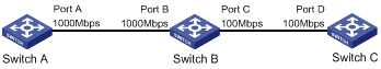
When TxRx mode generic flow control is enabled on Port B and Rx mode generic flow control is enabled on Port A:
· When Port C is congested, Switch B buffers the packet. When the buffered packets reach a size, Switch B learns that the traffic forwarded from Port B to Port C exceeds the forwarding capability of Port C. In this case, Port B sends generic pause frames to Port A and tells Port A to suspend sending packets.
· When Port A receives the generic pause frames, Port A suspends sending packets to Port B for a certain period, which is carried in the generic pause frames. Port B sends generic pause frames to Port A until congestion is removed.
To handle unidirectional traffic congestion on a link, configure the flow-control receive enable command at one end and the flow-control command at the other end. To enable both ends of a link to handle traffic congestion, configure the flow-control command at both ends.
To enable generic flow control on an Ethernet interface:
|
Step |
Command |
Remarks |
|
1. Enter system view. |
system-view |
N/A |
|
2. Enter Ethernet interface view. |
interface interface-type interface-number |
N/A |
|
3. Enable generic flow control. |
·
Enable TxRx mode
generic flow control: ·
Enable Rx mode
generic flow control: |
By default, generic flow control is disabled on an Ethernet interface. |
Configuring PFC on an Ethernet interface
|
|
IMPORTANT: This feature is available only when the system operates in advanced mode. For more information about system operating modes, see Fundamentals Configuration Guide. |
PFC performs flow control based on 802.1p priorities. With PFC enabled, an interface requires its peer to suspend sending packets with the specified 802.1p priorities when congestion occurs. By decreasing the transmission rate, PFC helps avoid packet loss.
You can enable PFC for the specified 802.1p priorities at the two ends of a link. When network congestion occurs, the local device checks the PFC status for the 802.1p priority carried in each arriving packet. The device processes the packet depending on the PFC status as follows:
· If PFC is enabled for the 802.1p priority, the local device accepts the packet and sends a PFC pause frame to the peer. The peer stops sending packets carrying this 802.1p priority for an interval as specified in the PFC pause frame. This process is repeated until the congestion is removed.
· If PFC is disabled for the 802.1p priority, the local interface drops the packet.
To configure PFC on an Ethernet interface:
|
Step |
Command |
Remarks |
|
1. Enter system view. |
system-view |
N/A |
|
2. Enter Ethernet interface view. |
interface interface-type interface-number |
N/A |
|
3. Enable PFC on the interface through automatic negotiation or forcibly. |
priority-flow-control { auto | enable } |
By default, PFC is disabled. |
|
4. Enable PFC for specific 802.1p priorities. |
priority-flow-control no-drop dot1p dot1p-list |
By default, PFC is disabled for all 802.1p priorities. |
When you configure PFC, follow these guidelines:
· To perform PFC on a network interface of an IRF member device, configure PFC on both the network interface and the IRF physical interfaces. For information about IRF, see IRF configuration Guide.
· As a best practice to ensure correct operations of IRF and other protocols, do not enable PFC for 802.1p priorities 0, 6, and 7.
· Make the same PFC configuration on all interfaces that traffic travels through.
· An interface can receive PFC pause frames whether or not PFC is enabled on the interface. However, only an interface with PFC enabled can process PFC pause frames. To make PFC take effect, make sure PFC is enabled on both the local end and the peer end.
The relationship between the PFC function and the generic flow control function is shown in Table 1.
Table 1 The relationship between the PFC function and the generic flow control function
|
flow-control |
priority-flow-control enable |
priority-flow-control no-drop dot1p |
Remarks |
|
Unconfigurable |
Configured |
Configured |
You cannot enable flow control by using the flow-control command on an interface where PFC is enabled and PFC is enabled for the specified 802.1p priority values. |
|
Configured |
Configurable |
Unconfigurable |
· On an interface configured with the flow-control command, you can enable PFC, but you cannot enable PFC for specific 802.1p priorities. · Enabling both generic flow control and PFC on an interface disables the interface from sending common or PFC pause frames to inform the peer of congestion conditions. However, the interface can still handle common and PFC pause frames from the peer. |
Enabling energy saving features on an Ethernet interface
Enabling auto power-down on an Ethernet interface
|
|
IMPORTANT: Fiber ports do not support this feature. |
When an Ethernet interface with auto power-down enabled has been down for a certain period of time, both of the following events occur:
· The device automatically stops supplying power to the Ethernet interface.
· The Ethernet interface enters the power save mode.
The time period depends on the chip specifications and is not configurable.
When the Ethernet interface comes up, both of the following events occur:
· The device automatically restores power supply to the Ethernet interface.
· The Ethernet interface restores to its normal state.
To enable auto power-down on an Ethernet interface:
|
Step |
Command |
Remarks |
|
1. Enter system view. |
system-view |
N/A |
|
2. Enter Ethernet interface view. |
interface interface-type interface-number |
N/A |
|
3. Enable auto power-down on the Ethernet interface. |
port auto-power-down |
By default, auto power-down is disabled on an Ethernet interface. |
Enabling EEE on an Ethernet interface
|
|
IMPORTANT: · Fiber ports do not support this feature. · Ports on an LSXM1GT48FX1 card do not support this feature when they operate at 100 Mbps. |
With Energy Efficient Ethernet (EEE) enabled, a link-up interface enters low power state if it has not received any packets for a period of time. The time period depends on the chip specifications and is not configurable. When a packet arrives later, the device automatically restores power supply to the interface and the interface restores to the normal state.
To enable EEE on an Ethernet interface:
|
Step |
Command |
Remarks |
|
1. Enter system view. |
system-view |
N/A |
|
2. Enter Ethernet interface view. |
interface interface-type interface-number |
N/A |
|
3. Enable EEE on the Ethernet interface. |
eee enable |
By default, EEE is disabled on an Ethernet interface. |
Configuring a Layer 2 Ethernet interface
Configuring storm suppression
You can use the storm suppression feature to limit the size of a particular type of traffic (broadcast, multicast, or unknown unicast traffic) on an interface. When the broadcast, multicast, or unknown unicast traffic on the interface exceeds this threshold, the system discards packets until the traffic drops below this threshold.
Any of the storm-constrain, broadcast-suppression, multicast-suppression, and unicast-suppression commands can suppress storm on an interface. The broadcast-suppression, multicast-suppression, and unicast-suppression commands suppress traffic in hardware, and have less impact on device performance than the storm-constrain command, which performs suppression in software.
Configuration guidelines
For the same type of traffic, do not configure the storm constrain command together with any of the broadcast-suppression, multicast-suppression, and unicast-suppression commands. Otherwise, the traffic suppression result is not determined. For more information about the storm-constrain command, see "Configuring storm control on an Ethernet interface."
Configuration procedure
To set storm suppression thresholds on one or multiple Ethernet interfaces:
|
Step |
Command |
Remarks |
|
1. Enter system view. |
system-view |
N/A |
|
2. Enter Ethernet interface view. |
interface interface-type interface-number |
N/A |
|
3. Enable broadcast suppression and set the broadcast suppression threshold. |
broadcast-suppression { ratio | pps max-pps | kbps max-kbps } |
By default, broadcast traffic is allowed to pass through an interface. |
|
4. Enable multicast suppression and set the multicast suppression threshold. |
multicast-suppression { ratio | pps max-pps | kbps max-kbps } |
By default, multicast traffic is allowed to pass through an interface. |
|
5. Enable unknown unicast suppression and set the unknown unicast suppression threshold. |
unicast-suppression { ratio | pps max-pps | kbps max-kbps } |
By default, unknown unicast traffic is allowed to pass through an interface. |
Configuring storm control on an Ethernet interface
About storm control
Storm control compares broadcast, multicast, and unknown unicast traffic regularly with their respective traffic thresholds on an Ethernet interface. For each type of traffic, storm control provides a lower threshold and a higher threshold.
For management purposes, you can configure the interface to output threshold event traps and log messages when monitored traffic meets either of the following conditions:
· Exceeds the upper threshold.
· Falls below the lower threshold from the upper threshold.
Depending on your configuration, when a particular type of traffic exceeds its upper threshold, the interface performs either of the following operations:
· Blocks this type of traffic and forwards other types of traffic—Even though the interface does not forward the blocked traffic, it still counts the traffic. When the blocked traffic drops below the lower threshold, the interface begins to forward the traffic.
· Goes down automatically—The interface goes down automatically and stops forwarding traffic. When the blocked traffic is detected dropping below the lower threshold, the interface does not forward the traffic. To bring up the interface, use the undo shutdown command or disable the storm control function.
Any of the storm-constrain, broadcast-suppression, multicast-suppression, and unicast-suppression commands can suppress storm on an interface. The broadcast-suppression, multicast-suppression, and unicast-suppression commands suppress traffic in hardware, and have less impact on device performance than the storm-constrain command, which performs suppression in software.
Storm control uses a complete polling cycle to collect traffic data, and analyzes the data in the next cycle. An interface takes one to two polling intervals to take a storm control action.
Configuration guidelines
For the same type of traffic, do not configure the storm constrain command together with any of the broadcast-suppression, multicast-suppression, and unicast-suppression commands. Otherwise, the traffic suppression result is not determined. For more information about the broadcast-suppression, multicast-suppression, and unicast-suppression commands, see "Configuring storm suppression."
Configuration procedure
To configure storm control on an Ethernet interface:
|
Step |
Command |
Remarks |
|
1. Enter system view. |
system-view |
N/A |
|
2. (Optional.) Set the traffic polling interval of the storm control module. |
storm-constrain interval seconds |
The default setting is 10 seconds. For network stability, use the default or set a higher traffic polling interval (10 seconds). |
|
3. Enter Ethernet interface view. |
interface interface-type interface-number |
N/A |
|
4. (Optional.) Enable storm control, and set the lower and upper thresholds for broadcast, multicast, or unknown unicast traffic. |
storm-constrain { broadcast | multicast | unicast } { pps | kbps | ratio } max-pps-values min-pps-values |
By default, storm control is disabled. |
|
5. Set the control action to take when monitored traffic exceeds the upper threshold. |
storm-constrain control { block | shutdown } |
By default, storm control is disabled. |
|
6. (Optional.) Enable the interface to log storm control threshold events. |
storm-constrain enable log |
By default, the interface outputs log messages when monitored traffic exceeds the upper threshold or falls below the lower threshold from the upper threshold. |
|
7. (Optional.) Enable the interface to send storm control threshold event traps. |
storm-constrain enable trap |
By default, the interface sends traps when monitored traffic exceeds the upper threshold or drops below the lower threshold from the upper threshold. |
Forcibly bringing up a fiber port
|
|
CAUTION: The following operations on a fiber port will cause link updown events before the port finally stays up: · Configure both the port up-mode command and the speed or duplex command. · Install or remove fiber links or transceiver modules after you forcibly bring up the fiber port. |
|
|
IMPORTANT: Copper ports do not support this feature. |
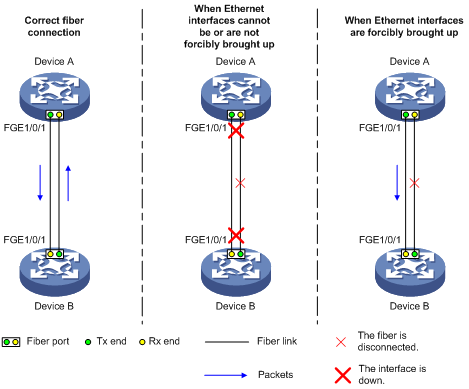
As shown in Figure 2, a fiber port uses separate fibers for transmitting and receiving packets. The physical state of the fiber port is up only when both transmit and receive fibers are physically connected. If one of the fibers is disconnected, the fiber port does not work.
To enable a fiber port to forward traffic over a single link, use the port up-mode command. This command forcibly brings up a fiber port, even when no fiber links or transceiver modules are present for the fiber port. When one fiber link is present and up, the fiber port can forward packets over the link unidirectionally.
Figure 2 Forcibly bring up a fiber port
Configuration restrictions and guidelines
When you forcibly bring up a fiber port, follow these restrictions and guidelines:
· To enable this feature on a fiber port, make sure the port is operating in bridge mode.
· The port up-mode and shutdown commands are mutually exclusive.
· A GE fiber port forcibly brought up cannot correctly forward traffic if it is installed with a fiber-to-copper converter, 100/1000-Mbps transceiver module, or 100-Mbps transceiver module. To solve the problem, use the undo port up-mode command on the fiber port.
To forcibly bring up a fiber port:
|
Step |
Command |
Remarks |
|
1. Enter system view. |
system-view |
N/A |
|
2. Enter Ethernet interface view. |
interface interface-type interface-number |
N/A |
|
3. Forcibly bring up the fiber port. |
port up-mode |
By default, a fiber port is not forcibly brought up, and the physical state of a fiber port depends on the physical state of the fibers. |
Setting the MDIX mode of an Ethernet interface
|
|
IMPORTANT: Fiber ports do not support this feature. |
A physical Ethernet interface has eight pins. Each pin plays a dedicated role by default. For example, pins 1 and 2 receive signals, and pins 3 and 6 transmit signals. You can use both crossover and straight-through Ethernet cables to connect copper Ethernet interfaces. To accommodate these types of cables, a copper Ethernet interface can operate in one of the following Medium Dependent Interface-Crossover (MDIX) modes:
· MDIX mode—Pins 1 and 2 are receive pins and pins 3 and 6 are transmit pins.
· MDI mode—Pins 1 and 2 are transmit pins and pins 3 and 6 are receive pins.
· AutoMDIX mode—The interface negotiates pin roles with its peer.
For a copper Ethernet interface to communicate with its peer, set the MDIX mode of the interface by following these guidelines:
· Typically, set the MDIX mode of the interface to AutoMDIX. Set the MDIX mode of the interface to MDI or MDIX only when the device cannot determine the cable type.
· When a straight-through cable is used, configure the interface to operate in an MDIX mode different than its peer.
· When a crossover cable is used, perform one of the following tasks:
¡ Configure the interface to operate in the same MDIX mode as its peer.
¡ Configure either end to operate in AutoMDIX mode.
To set the MDIX mode of an Ethernet interface:
|
Step |
Command |
Remarks |
|
1. Enter system view. |
system-view |
N/A |
|
2. Enter Ethernet interface view. |
interface interface-type interface-number |
N/A |
|
3. Set the MDIX mode of the Ethernet interface. |
mdix-mode { automdix | mdi | mdix } |
By default, a copper Ethernet interface operates in auto mode to negotiate pin roles with its peer. |
Testing the cable connection of an Ethernet interface
|
|
IMPORTANT: · Fiber ports do not support this feature. · If the link of an Ethernet interface is up, testing its cable connection will cause the link to go down and then come up. |
This feature tests the cable connection of an Ethernet interface and displays cable test result within 5 seconds. The test result includes the cable's status and some physical parameters. If a fault is detected, the test result shows the length from the local interface to the faulty point.
To test the cable connection of an Ethernet interface:
|
Step |
Command |
|
1. Enter system view. |
system-view |
|
2. Enter Ethernet interface view. |
interface interface-type interface-number |
|
3. Perform a test for the cable connected to the Ethernet interface. |
virtual-cable-test |
Configuring a Layer 3 Ethernet interface or subinterface
Setting the MTU for an Ethernet interface or subinterface
The maximum transmission unit (MTU) of an Ethernet interface affects the fragmentation and reassembly of IP packets on the interface. Typically, you do not need to modify the MTU of an interface.
To set the MTU for an Ethernet interface or subinterface:
|
Step |
Command |
Remarks |
|
1. Enter system view. |
system-view |
N/A |
|
2. Enter Ethernet interface or subinterface view. |
interface interface-type { interface-number | interface-number.subnumber } |
N/A |
|
3. Set the MTU for the Ethernet interface or subinterface. |
mtu size |
By default, the MTU of an Ethernet interface or subinterface is 1500 bytes. |
Displaying and maintaining an Ethernet interface
Execute display commands in any view and reset commands in user view.
|
Task |
Command |
|
Display interface traffic statistics. |
display counters { inbound | outbound } interface [ interface-type [ interface-number ] ] |
|
Display traffic rate statistics of interfaces in up state over the last sampling interval. |
display counters rate { inbound | outbound } interface [ interface-type [ interface-number ] ] |
|
Display the operational and status information of the specified interface or all interfaces. |
display interface [ interface-type [ interface-number | interface-number.subnumber ] ] |
|
Display summary information about the specified interface or all interfaces. |
display interface [ interface-type [ interface-number | interface-number.subnumber ] ] brief [ description ] |
|
Display information about dropped packets on the specified interface or all interfaces. |
display packet-drop { interface [ interface-type [ interface-number ] ] | summary } |
|
Display information about storm control on the specified interface or all interfaces. |
display storm-constrain [ broadcast | multicast | unicast ] [ interface interface-type interface-number ] |
|
Display the Ethernet module statistics. |
display ethernet statistics |
|
Clear the interface statistics. |
reset counters interface [ interface-type [ interface-number ] ] |
|
Clear the statistics of dropped packets on the specified interfaces. |
reset packet-drop interface [ interface-type [ interface-number ] ] |
|
Clear the Ethernet module statistics. |
reset ethernet statistics |