- Table of Contents
-
- 03-Layer 2-LAN Switching Configuration Guide
- 00-Preface
- 01-Ethernet interface configuration
- 02-Loopback, null, and inloopback interface configuration
- 03-Bulk interface configuration
- 04-MAC address table configuration
- 05-Ethernet link aggregation configuration
- 06-Port isolation configuration
- 07-Spanning tree configuration
- 08-Loop detection configuration
- 09-VLAN configuration
- 10-VLAN mapping configuration
- 11-LLDP configuration
- 12-Service loopback group configuration
- Related Documents
-
| Title | Size | Download |
|---|---|---|
| 09-VLAN configuration | 191.44 KB |
Contents
Configuring basic VLAN settings
Configuring basic settings of a VLAN interface
Reserving VLAN interface resources
Reserving local-type VLAN interface resources
Reserving global-type VLAN interface resources
Configuration restrictions and guidelines
Introduction to port-based VLAN
Assigning an access port to a VLAN
Assigning a trunk port to a VLAN
Assigning a hybrid port to a VLAN
Displaying and maintaining VLANs
Configuring VLANs
Overview
Ethernet is a family of shared-media LAN technologies based on the CSMA/CD mechanism. An Ethernet LAN is both a collision domain and a broadcast domain. Because the medium is shared, collisions and broadcasts are common in an Ethernet LAN. Typically, bridges and Layer 2 switches can reduce collisions in an Ethernet LAN. To confine broadcasts, a Layer 2 switch must use the Virtual Local Area Network (VLAN) technology.
VLANs enable a Layer 2 switch to break a LAN down into smaller broadcast domains, as shown in Figure 1.
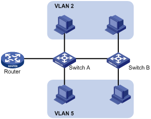
A VLAN is logically divided on an organizational basis rather than on a physical basis. For example, you can assign all workstations and servers used by a particular workgroup to the same VLAN, regardless of their physical locations. Hosts in the same VLAN can directly communicate with one another. You need a router or a Layer 3 switch for hosts in different VLANs to communicate with one another.
All these VLAN features reduce bandwidth waste, improve LAN security, and enable flexible virtual group creation.
VLAN frame encapsulation
To identify Ethernet frames from different VLANs, IEEE 802.1Q inserts a four-byte VLAN tag between the destination and source MAC address (DA&SA) field and the upper layer protocol type (Type) field, as shown in Figure 2.
Figure 2 VLAN tag placement and format
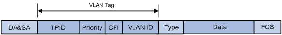
A VLAN tag includes the following fields:
· TPID—16-bit tag protocol identifier that indicates whether a frame is VLAN-tagged. By default, the TPID value is 0x8100, indicating that the frame is VLAN-tagged. However, device vendors can set TPID to different values. For compatibility with neighbor devices, configure the TPID value on the device to be the same as the neighbor device.
· Priority—3-bit long, identifies the 802.1p priority of the frame. For more information, see ACL and QoS Configuration Guide.
· CFI—1-bit long canonical format indicator that indicates whether the MAC addresses are encapsulated in the standard format when packets are transmitted across different media. The possible values are:
¡ 0 (default)—The MAC addresses are encapsulated in the standard format.
¡ 1—The MAC addresses are encapsulated in a non-standard format.
This field is always set to 0 for Ethernet.
· VLAN ID—12-bit long, identifies the VLAN that the frame belongs to. The VLAN ID range is 0 to 4095. VLAN IDs 0 and 4095 are reserved, and VLAN IDs 1 to 4094 are user configurable.
The way a network device handles an incoming frame depends on whether the frame is VLAN-tagged and the value of the VLAN tag (if any). For more information, see "Introduction to port-based VLAN."
Ethernet supports encapsulation formats Ethernet II, 802.3/802.2 LLC, 802.3/802.2 SNAP, and 802.3 raw. The Ethernet II encapsulation format is used here. For how the VLAN tag fields are added to frames encapsulated in the other formats for VLAN identification, see related protocols and standards.
For a frame with multiple VLAN tags, the device handles it according to its outer-most VLAN tag and transmits its inner VLAN tags as the payload.
Protocols and standards
IEEE 802.1Q, IEEE Standard for Local and Metropolitan Area Networks: Virtual Bridged Local Area Networks
Configuring basic VLAN settings
|
Step |
Command |
Remarks |
|
1. Enter system view. |
system-view |
N/A |
|
2. (Optional.) Create a VLAN and enter its view, or create a list of VLANs. |
vlan { vlan-id1 [ to vlan-id2 ] | all } |
By default, only the system default VLAN (VLAN 1) exists. |
|
3. Enter VLAN view. |
vlan vlan-id |
To configure a specific VLAN after you create a list of VLANs, you must perform this step. |
|
4. Configure a name for the VLAN. |
name text |
By default, the name of a VLAN is VLAN vlan-id. The vlan-id argument specifies the VLAN ID in a four-digit format. If the VLAN ID has fewer than four digits, leading zeros are added. For example, the name of VLAN 100 is VLAN 0100. |
|
5. Configure the description of the VLAN. |
description text |
By default, the description of a VLAN is VLAN vlan-id. The vlan-id argument specifies the VLAN ID in a four-digit format. If the VLAN ID has fewer than four digits, leading zeros are added. For example, the default description of VLAN 100 is VLAN 0100. |
|
|
NOTE: · As the system default VLAN, VLAN 1 cannot be created or deleted. · Before you delete a dynamic VLAN, a VLAN configured with a QoS policy, or a VLAN locked by an application, you must first remove the configuration from the VLAN. |
Configuring basic settings of a VLAN interface
For hosts of different VLANs to communicate at Layer 3, you can use VLAN interfaces. VLAN interfaces are virtual interfaces used for Layer 3 communication between different VLANs. They do not exist as physical entities on devices. For each VLAN, you can create one VLAN interface. You can assign an IP address to it. The VLAN interface acts as the gateway of the VLAN to forward packets destined for another IP subnet.
Before you create a VLAN interface for a VLAN, create the VLAN first.
To configure basic settings of a VLAN interface:
|
Step |
Command |
Remarks |
|
1. Enter system view. |
system-view |
N/A |
|
2. Create a VLAN interface and enter VLAN interface view. |
interface vlan-interface vlan-interface-id |
If the VLAN interface already exists, you enter its view directly. By default, no VLAN interface is created. |
|
3. Assign an IP address to the VLAN interface. |
ip address ip-address { mask | mask-length } [ sub ] |
By default, no IP address is assigned to any VLAN interface. |
|
4. Configure the description of the VLAN interface. |
description text |
The default setting is the VLAN interface name. For example, Vlan-interface1 Interface. |
|
5. (Optional.) Specify a line processing unit (LPU) for forwarding the traffic on the current VLAN interface (in standalone mode). |
·
In standalone mode: ·
In IRF mode: |
By default, no LPU is specified. |
|
6. Set the MTU for the VLAN interface. |
By default, the MTU for a VLAN interface is 1500 bytes. |
|
|
7. Configure the expected bandwidth of the interface. |
bandwidth bandwidth-value |
By default, the expected bandwidth (in kbps) is the interface baud rate divided by 1000. |
|
8. (Optional.) Restore the default settings for the VLAN interface. |
default |
N/A |
|
9. (Optional.) Bring up the VLAN interface. |
undo shutdown |
By default, a VLAN interface is not manually shut down. The VLAN interface is up if one or more ports in the VLAN is up, and goes down if all ports in the VLAN go down. |
Reserving VLAN interface resources
The system provides 4094 Layer 3 interface hardware resources for Layer 3 interfaces and subinterfaces. By default, these Layer 3 interface resources are assigned to 4094 VLAN interfaces.
Reserve VLAN interface resources before you perform the following tasks:
· Create Layer 3 interfaces and subinterfaces, except VLAN interfaces.
· Configure features that require Layer 3 interface hardware resources.
A reserved VLAN interface resource can be of the local or global type.
Reserving local-type VLAN interface resources
Reserve local-type VLAN interface resources before you perform the following tasks:
· Switch Layer 2 Ethernet interfaces to Layer 3 Ethernet interfaces.
· Create Layer 3 Ethernet subinterfaces, Layer 3 aggregate interfaces, and Layer 3 aggregate subinterfaces.
· Create VPN instances on a PE device on the MPLS L3VPN network. For more information about MPLS L3VPN, see MPLS Configuration Guide.
Each of the Layer 3 Ethernet interfaces and subinterfaces uses one local-type VLAN interface resource. When you reserve local-type VLAN interface resources for interfaces that have subinterfaces, take the number of the subinterfaces into account. For example:
· Reserve two local-type VLAN interface resources when you create a Layer 3 Ethernet subinterface. The main interface and subinterface each use one local-type VLAN interface resource.
· Reserve seven local-type VLAN interface resources when you create four Layer 3 aggregate subinterfaces on an aggregate interface whose corresponding aggregation group has two member ports. The aggregate interface uses one local-type VLAN interface. Each of the member ports and aggregate subinterfaces uses one local-type VLAN interface resource.
Each MPLS L3VPN instance uses one local-type VLAN interface resource. Reserve a local-type VLAN interface resource before you create an MPLS L3VPN instance.
Reserving global-type VLAN interface resources
If you set the VXLAN forwarding mode to Layer 3, you must reserve one global-type VLAN interface resource for each VSI interface before it is created. For more information about VSI interfaces, see VXLAN Configuration Guide.
Before you create tunnel interfaces, you must reserve global-type VLAN interface resources for them. Each tunnel interface requires two global-type VLAN interface resources. For more information about tunnel interfaces, see Layer 3—IP Services Configuration Guide.
Configuration restrictions and guidelines
When you reserve VLAN interface resources, follow these restrictions and guidelines:
· As a best practice to simplify management and configuration, reserve VLAN interface resources as follows:
¡ Bulk reserve resources of VLAN interfaces that are numbered in consecutive order.
¡ Preferentially reserve resources of VLAN interfaces whose VLAN IDs are in the range of 3000 to 3500.
· Select the VLAN interfaces of unused VLANs rather than used VLANs for resource reservation. As a best practice, do not create or use a VLAN if the VLAN interface resource of the VLAN is reserved.
· The VLAN interface resource reservation of a VLAN conflicts with the VLAN interface creation of this VLAN.
· Do not reserve VLAN interface resources of reserved VLANs (for example, the primary control VLAN and the secondary control VLAN in RRPP). Otherwise, features that use these reserved VLAN interface resources might not operate correctly. To display reserved VLANs, use the display vlan reserved command.
· Before creating a Layer 3 Ethernet subinterface or aggregate subinterface, do not reserve a resource for the VLAN interface whose interface number matches the subinterface number. After you reserve a VLAN interface resource, do not create a Layer 3 Ethernet subinterface or aggregate subinterface whose subinterface number is the VLAN interface number. A Layer 3 Ethernet subinterface or aggregate subinterface uses the VLAN interface resource in processing tagged packets whose VLAN ID matches the subinterface number.
· A reserved VLAN interface resource can be of the local or global type. To change the type of a reserved VLAN interface resource, first remove the reservation.
· You cannot remove the reservation of a VLAN interface resource if this resource has been used.
· This feature is available in Feature 1108 and later versions. After the software upgrades to support this feature, first reserve VLAN interface resources for existing configurations that require the reservation.
Configuration procedure
To reserve VLAN interface resources:
|
Step |
Command |
Remarks |
|
1. Enter system view. |
system-view |
N/A |
|
2. Reserve VLAN interface resources. |
reserve-vlan-interface { vlan-interface-id1 [ to vlan-interface-id2 ] [ global ] } |
By default, no VLAN interface resources are reserved. To reserve global-type VLAN interface resources, specify the global keyword. To reserve local-type VLAN interface resources, do not specify the global keyword. |
|
3. (Optional.) Display VLANs whose VLAN interface resources have been reserved. |
display reserve-vlan-interface |
N/A |
Configuring port-based VLANs
Introduction to port-based VLAN
Port-based VLANs group VLAN members by port. A port forwards packets from a VLAN only after it is assigned to the VLAN.
Port link type
You can configure the link type of a port as access, trunk, or hybrid. The link types use the following VLAN tag handling methods:
· Access—An access port can forward packets from only one specific VLAN and send these packets untagged. An access port can connect a terminal device that does not support VLAN packets or is used in scenarios that do not distinguish VLANs.
· Trunk—A trunk port can forward packets from multiple VLANs. Except packets from the port VLAN ID (PVID), packets sent out of a trunk port are VLAN-tagged. Ports connecting network devices are typically configured as trunk ports.
· Hybrid—A hybrid port can forward packets from multiple VLANs. A hybrid port allows traffic from some VLANs to pass through untagged and traffic from other VLANs to pass through tagged. A hybrid port can connect a network device or terminal device.
PVID
The PVID identifies the port VLAN of a port.
When you configure the PVID on a port, follow these restrictions and guidelines:
· An access port can join only one VLAN. The VLAN to which the access port belongs is the PVID of the port.
· A trunk or hybrid port supports multiple VLANs and the PVID configuration.
· When you use the undo vlan command to delete the PVID of a port, either of the following events occurs depending on the port link type:
¡ For an access port, the PVID of the port changes to VLAN 1.
¡ For a hybrid or trunk port, the PVID setting of the port does not change.
You can use a nonexistent VLAN as the PVID for a hybrid or trunk port, but not for an access port.
· To correctly transmit packets, configure the same PVID for local and remote ports.
· To prevent a port from dropping untagged packets or PVID-tagged packets, assign the port to its PVID.
How ports of different link types handle frames
|
Actions |
Access |
Trunk |
Hybrid |
|
|
In the inbound direction for an untagged frame |
Tags the frame with the PVID tag. |
· If the PVID is permitted on the port, tags the frame with the PVID tag. · If not, drops the frame. |
||
|
In the inbound direction for a tagged frame |
· Receives the frame if its VLAN ID is the same as the PVID. · Drops the frame if its VLAN ID is different from the PVID. |
· Receives the frame if its VLAN is permitted on the port. · Drops the frame if its VLAN is not permitted on the port. |
||
|
In the outbound direction |
Removes the VLAN tag and sends the frame. |
· Removes the tag and sends the frame if the frame carries the PVID tag and the port belongs to the PVID. · Sends the frame without removing the tag if its VLAN is carried on the port but is different from the PVID. |
Sends the frame if its VLAN is permitted on the port. The tagging status of the frame depends on the port hybrid vlan command configuration. |
|
Assigning an access port to a VLAN
You can assign an access port to a VLAN in VLAN view or interface view.
Make sure the VLAN has been created.
Assigning one or multiple access ports to a VLAN in VLAN view
|
Step |
Command |
Remarks |
|
1. Enter system view. |
system-view |
N/A |
|
2. Enter VLAN view. |
vlan vlan-id |
N/A |
|
3. Assign one or a group of access ports to the VLAN. |
port interface-list |
By default, all ports belong to VLAN 1. |
Assigning an access port to a VLAN in interface view
|
Step |
Command |
Remarks |
|
1. Enter system view. |
system-view |
N/A |
|
2. Enter interface view. |
·
Enter Layer 2 Ethernet interface view: ·
Enter Layer 2 aggregate interface view: |
· The configuration made in Layer 2 Ethernet interface view applies only to the port. · The configuration made in Layer 2 aggregate interface view applies to the aggregate interface and its aggregation member ports. If the system fails to apply the configuration to an aggregation member port, it skips the port and moves to the next member port. If the system fails to apply the configuration to the aggregate interface, it stops applying the configuration to aggregation member ports. |
|
3. Configure the link type of the port as access. |
port link-type access |
By default, all ports are access ports. |
|
4. (Optional.) Assign the access port to a VLAN. |
port access vlan vlan-id |
By default, all access ports belong to VLAN 1. |
Assigning a trunk port to a VLAN
A trunk port supports multiple VLANs. You can assign it to a VLAN in interface view.
When you assign a trunk port to a VLAN, follow these guidelines:
· To change the link type of a port from trunk to hybrid or vice versa, set the link type to access first.
· To enable a trunk port to transmit packets from its PVID, you must assign the trunk port to the PVID by using the port trunk permit vlan command.
To assign a trunk port to one or multiple VLANs:
|
Step |
Command |
Remarks |
|
1. Enter system view. |
system-view |
N/A |
|
2. Enter interface view. |
·
Enter Layer 2 Ethernet interface view: ·
Enter Layer 2 aggregate interface view: |
· The configuration made in Layer 2 Ethernet interface view applies only to the port. · The configuration made in Layer 2 aggregate interface view applies to the aggregate interface and its aggregation member ports. If the system fails to apply the configuration to an aggregation member port, it skips the port and moves to the next member port. If the system fails to apply the configuration to the aggregate interface, it stops applying the configuration to aggregation member ports. |
|
3. Configure the link type of the port as trunk. |
port link-type trunk |
By default, all ports are access ports. |
|
4. Assign the trunk port to the specified VLANs. |
port trunk permit vlan { vlan-id-list | all } |
By default, a trunk port only permits VLAN 1. |
|
5. (Optional.) Configure the PVID of the trunk port. |
port trunk pvid vlan vlan-id |
The default setting is VLAN 1. |
Assigning a hybrid port to a VLAN
A hybrid port supports multiple VLANs. You can assign it to the specified VLANs in interface view. Make sure the VLANs have been created.
When you assign a hybrid port to a VLAN, follow these guidelines:
· To change the link type of a port from trunk to hybrid or vice versa, set the link type to access first.
· To enable a hybrid port to transmit packets from its PVID, you must assign the hybrid port to the PVID by using the port hybrid vlan command.
To assign a hybrid port to one or multiple VLANs:
|
Step |
Command |
Remarks |
|
1. Enter system view. |
system-view |
N/A |
|
2. Enter interface view. |
·
Enter Layer 2 Ethernet interface view: ·
Enter Layer 2 aggregate interface view: |
· The configuration made in Layer 2 Ethernet interface view applies only to the port. · The configuration made in Layer 2 aggregate interface view applies to the aggregate interface and its aggregation member ports. If the system fails to apply the configuration to an aggregation member port, it skips the port and moves to the next member port. If the system fails to apply the configuration to the aggregate interface, it stops applying the configuration to aggregation member ports. |
|
3. Configure the link type of the port as hybrid. |
port link-type hybrid |
By default, all ports are access ports. |
|
4. Assign the hybrid port to the specified VLANs. |
port hybrid vlan vlan-id-list { tagged | untagged } |
By default, a hybrid port is an untagged member of the VLAN to which the port belongs when its link type is access. |
|
5. (Optional.) Configure the PVID of the hybrid port. |
port hybrid pvid vlan vlan-id |
By default, the PVID of a hybrid port is the ID of the VLAN to which the port belongs when its link type is access. |
Displaying and maintaining VLANs
Execute display commands in any view.
|
Task |
Command |
|
Display VLAN information. |
display vlan [ vlan-id1 [ to vlan-id2 ] | all | dynamic | reserved | static ] |
|
Display brief VLAN information. |
|
|
Display VLAN interface information. |
display interface vlan-interface [ vlan-interface-id ] [ brief [ description ] ] |
|
Display hybrid ports or trunk ports. |
display port { hybrid | trunk } |
|
Display VLANs whose VLAN interface resources have been reserved. |
display reserve-vlan-interface [ global ] |
Port-based VLAN configuration example
Network requirements
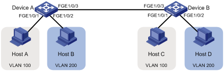
As shown in Figure 3:
· Host A and Host C belong to Department A. VLAN 100 is assigned to Department A.
· Host B and Host D belong to Department B. VLAN 200 is assigned to Department B.
Configure port-based VLANs so that hosts only in the same department can communicate with each other.
Configuration procedure
1. Configure Device A:
# Create VLAN 100, and assign FortyGigE 1/0/1 to VLAN 100.
<DeviceA> system-view
[DeviceA] vlan 100
[DeviceA-vlan100] port fortygige 1/0/1
[DeviceA-vlan100] quit
# Create VLAN 200, and assign FortyGigE 1/0/2 to VLAN 200.
[DeviceA] vlan 200
[DeviceA-vlan200] port fortygige 1/0/2
[DeviceA-vlan200] quit
# Configure FortyGigE 1/0/3 as a trunk port, and assign it to VLANs 100 and 200.
[DeviceA] interface fortygige 1/0/3
[DeviceA-FortyGigE1/0/3] port link-type trunk
[DeviceA-FortyGigE1/0/3] port trunk permit vlan 100 200
Please wait... Done.
2. Configure Device B in the same way Device A is configured. (Details not shown.)
3. Configure hosts:
¡ Configure Host A and Host C to be on the same IP subnet. For example, 192.168.100.0/24.
¡ Configure Host B and Host D to be on the same IP subnet. For example, 192.168.200.0/24.
Verifying the configuration
# Verify that Host A and Host C can ping each other, but they both fail to ping Host B. (Details not shown.)
# Verify that Host B and Host D can ping each other, but they both fail to ping Host A. (Details not shown.)
# Verify that VLANs 100 and 200 are correctly configured on devices, for example, on Device A.
[DeviceA-FortyGigE1/0/3] display vlan 100
VLAN ID: 100
VLAN type: Static
Route interface: Not configured
Description: VLAN 0100
Name: VLAN 0100
Tagged ports:
FortyGigE1/0/3
Untagged ports:
FortyGigE1/0/1
[DeviceA-FortyGigE1/0/3] display vlan 200
VLAN ID: 200
VLAN type: Static
Route interface: Not configured
Description: VLAN 0200
Name: VLAN 0200
Tagged ports:
FortyGigE1/0/3
Untagged ports:
FortyGigE1/0/2