- Table of Contents
-
- 03-Layer 2-LAN Switching Configuration Guide
- 00-Preface
- 01-Ethernet interface configuration
- 02-Loopback, null, and inloopback interface configuration
- 03-Bulk interface configuration
- 04-MAC address table configuration
- 05-Ethernet link aggregation configuration
- 06-Port isolation configuration
- 07-Spanning tree configuration
- 08-Loop detection configuration
- 09-VLAN configuration
- 10-VLAN mapping configuration
- 11-LLDP configuration
- 12-Service loopback group configuration
- Related Documents
-
| Title | Size | Download |
|---|---|---|
| 10-VLAN mapping configuration | 325.01 KB |
Contents
VLAN mapping application scenarios
Configuration restrictions and guidelines
VLAN mapping configuration task list
Configuring one-to-one VLAN mapping
Configuring one-to-two VLAN mapping
Configuring zero-to-two VLAN mapping
Configuring two-to-two VLAN mapping
Configuring two-to-three VLAN mapping
Displaying and maintaining VLAN mapping
VLAN mapping configuration examples
One-to-one VLAN mapping configuration example
One-to-two and two-to-two VLAN mapping configuration example
Configuring VLAN mapping
Overview
VLAN mapping re-marks VLAN tagged traffic with new VLAN IDs. H3C provides the following types of VLAN mapping:
· One-to-one VLAN mapping—Replaces one VLAN tag with another.
· One-to-two VLAN mapping—Adds single-tagged packets with an outer VLAN tag.
· Zero-to-two VLAN mapping—Adds untagged packets with two VLAN tags.
· Two-to-two VLAN mapping—Replaces the outer and inner VLAN IDs of double tagged traffic with a new pair of VLAN IDs.
· Two-to-three VLAN mapping—Adds double-tagged packets with an outermost VLAN tag.
VLAN mapping application scenarios
One-to-one VLAN mapping
Figure 1 shows a typical application scenario of one-to-one VLAN mapping. The scenario implements broadband Internet access for a community.
Figure 1 Application scenario of one-to-one VLAN mapping
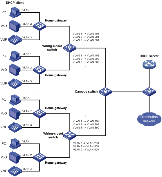
As shown in Figure 1, the network is implemented as follows:
· Each home gateway uses different VLANs to transmit the PC, VoD, and VoIP services.
· To further subclassify each type of traffic by customer, configure one-to-one VLAN mapping on the wiring-closet switches. This feature assigns a separate VLAN for each type of traffic from each customer. The required total number of VLANs in the network can be very large.
One-to-two and two-to-two VLAN mapping
Figure 2 shows a typical application scenario of one-to-two and two-to-two VLAN mapping. In this scenario, the two remote sites of the same VPN must communicate across two SP networks.
Figure 2 Application scenario of one-to-two and two-to-two VLAN mapping
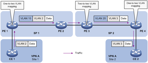
Site 1 and Site 2 are in VLAN 2 and VLAN 3, respectively. The SP 1 network assigns SVLAN 10 to Site 1. The SP 2 network assigns SVLAN 20 to Site 2. When the packet from Site 1 arrives at PE 1, PE 1 tags the packet with SVLAN 10 by using one-to-two VLAN mapping.
When the double-tagged packet from the SP 1 network arrives at the SP 2 network interface, PE 3 processes the packet as follows:
· Replaces SVLAN tag 10 with SVLAN 20.
· Replaces CVLAN tag 2 with CVLAN tag 3.
One-to-two VLAN mapping provides the following benefits:
· Enables a customer network to plan its CVLAN assignment without conflicting with SVLANs.
· Adds a VLAN tag to a tagged packet and expands the number of available VLANs to 4094 × 4094.
· Reduces the stress on the SVLAN resources, which were 4094 VLANs in the SP network before the mapping process was initiated.
Zero-to-two VLAN mapping
The application scenario of zero-to-two VLAN mapping is similar to the scenario of one-to-two VLAN mapping. Zero-to-two VLAN mapping is used on the customer-side port of a PE to add double tags to untagged packets.
Two-to-three VLAN mapping
The application scenario of two-to-three VLAN mapping is similar to the scenario of one-to-two VLAN mapping. Two-to-three VLAN mapping is used on the customer-side port of a PE to add an outermost VLAN tag to double-tagged packets.
VLAN mapping implementations
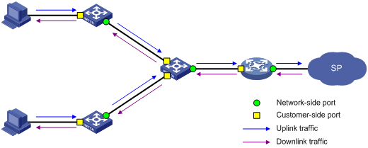
Figure 3 shows a simplified network that illustrates basic VLAN mapping terms.
Basic VLAN mapping terms include the following:
· Uplink traffic—Traffic transmitted from the customer network to the service provider network.
· Downlink traffic—Traffic transmitted from the service provider network to the customer network.
· Network-side port—A port connected to or closer to the service provider network.
· Customer-side port—A port connected to or closer to the customer network.
Figure 3 Basic VLAN mapping terms
One-to-one VLAN mapping
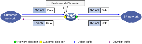
As shown in Figure 4, one-to-one VLAN mapping is implemented on the customer-side port and replaces VLAN tags as follows:
· Replaces the CVLAN with the SVLAN for the uplink traffic.
· Replaces the SVLAN with the CVLAN for the downlink traffic.
Figure 4 One-to-one VLAN mapping implementation
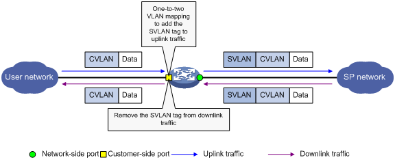
One-to-two VLAN mapping
As shown in Figure 5, one-to-two VLAN mapping is implemented on the customer-side port to add the SVLAN tag for the uplink traffic.
For the downlink traffic to be correctly sent to the customer network, use one of the following methods to remove the SVLAN tag from the traffic:
· Configure the customer-side port as a hybrid port and assign the port to the SVLAN as an untagged member.
· Configure the customer-side port as a trunk port, configure the SVLAN as the PVID, and assign the port to the PVID.
Figure 5 One-to-two VLAN mapping implementation
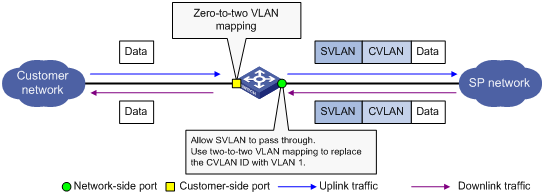
Zero-to-two VLAN mapping
As shown in Figure 6, zero-to-two VLAN mapping is implemented on the customer-side port to add double tags to untagged uplink traffic. For the zero-to-two VLAN mapping to take effect, the PVID of the customer-side port must be VLAN 1.
For correct downlink traffic transmission, the downlink traffic must be untagged or tagged with VLAN 1 when it is sent out of the customer-side port.
To tag the downlink traffic with VLAN 1:
1. Configure the network-side port to allow the traffic from the SVLAN to pass through.
2. If the CVLAN of the traffic is not VLAN 1, configure a two-to-two VLAN mapping on the network-side port to replace the CVLAN ID with VLAN 1.
3. Assign the customer-side port to the SVLAN as an untagged member.
Figure 6 Zero-to-two VLAN mapping implementation
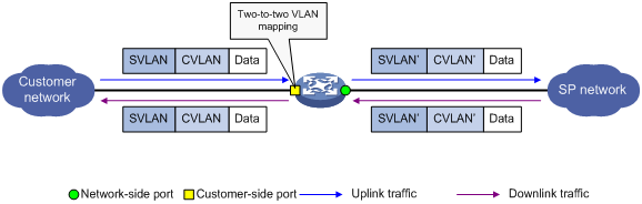
Two-to-two VLAN mapping
As shown in Figure 7, two-to-two VLAN mapping is implemented on the customer-side port and replaces VLAN tags as follows:
· Replaces the CVLAN and the SVLAN with the CVLAN' and the SVLAN' for the uplink traffic.
· Replaces the SVLAN' and CVLAN' with the SVLAN and the CVLAN for the downlink traffic.
Figure 7 Two-to-two VLAN mapping implementation
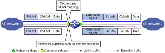
Two-to-three VLAN mapping
As shown in Figure 8, two-to-three VLAN mapping is implemented on the customer-side port to add an outermost VLAN tag to double-tagged uplink traffic.
For the downlink traffic to be correctly sent to the customer network, use one of the following methods to remove the outermost tag from the traffic:
· Configure the customer-side port as a trunk port, configure the outermost VLAN as the PVID, and assign the port to the PVID.
· Configure the customer-side port as a hybrid port and assign the port to the outermost VLAN as an untagged member.
Figure 8 Two-to-three VLAN mapping implementation
Configuration restrictions and guidelines
When you configure VLAN mapping, follow these restrictions and guidelines:
· Create original VLANs and translated VLANs before you configure VLAN mapping.
· Configure VLAN mapping on the customer-side port.
When you configure VLAN mapping with VXLAN, follow these restrictions and guidelines:
· VLAN mapping cannot be used together with the rewrite inbound tag or rewrite outbound tag command.
· The following settings are mutually exclusive on a chip:
¡ VLAN mapping.
¡ Ethernet service instance that matches an outer or inner VLAN ID range.
To view the mappings between interfaces and chips, use the debug port mapping command in probe view.
· The following settings are mutually exclusive on an interface:
¡ VLAN mapping.
¡ Ethernet service instance that matches inconsecutive outer or inner VLAN IDs.
VLAN mapping configuration task list
|
|
IMPORTANT: Use the appropriate VLAN mapping methods for the devices in the network. |
To configure VLAN mapping:
|
Task |
Remarks |
|
Configure one-to-one VLAN mapping on the wiring-closet switch, as shown in Figure 1. |
|
|
Configure one-to-two VLAN mapping on PE 1 and PE 4, as shown in Figure 2, through which traffic from customer networks enter the service provider networks. |
|
|
N/A |
|
|
Configure two-to-two VLAN mapping on PE 3, as shown in Figure 2, which is an edge device of the SP 2 network. |
|
|
N/A |
Configuring one-to-one VLAN mapping
Configure one-to-one VLAN mapping on the customer-side ports of wiring-closet switches (see Figure 1) to isolate traffic of the same service type from different homes.
To configure one-to-one VLAN mapping:
|
Step |
Command |
Remarks |
|
1. Enter system view. |
system-view |
N/A |
|
2. Enter Layer 2 Ethernet interface view or Layer 2 aggregate interface view. |
·
Enter Layer 2 Ethernet interface view: ·
Enter Layer 2 aggregate interface view: |
N/A |
|
3. Set the link type of the port. |
·
Set the port link type to trunk: ·
Set the port link type to hybrid: |
By default, the link type of a port is access. |
|
4. Assign the port to the original VLANs and the translated VLANs. |
·
For the trunk port: ·
For the hybrid port: |
By default, a trunk port is assigned only to VLAN 1, and a hybrid port is an untagged member of VLAN 1. |
|
5. Configure a one-to-one VLAN mapping. |
vlan mapping vlan-id translated-vlan vlan-id |
By default, VLAN mapping is not configured on an interface. |
Configuring one-to-two VLAN mapping
Configure one-to-two VLAN mapping on the customer-side ports of edge devices from which customer traffic enters SP networks, for example, on PE 1 and PE 4 in Figure 2. One-to-two VLAN mapping enables the edge devices to add an SVLAN tag to each incoming packet.
The MTU of an interface is 1500 bytes by default. After a VLAN tag is added to a packet through one-to-two VLAN mapping, the packet length is added by 4 bytes. As a best practice, set the MTU to a minimum of 1504 bytes for ports on the forwarding path of the packet in the service provider network.
To configure one-to-two VLAN mapping:
|
Step |
Command |
Remarks |
|
1. Enter system view. |
system-view |
N/A |
|
1. Enter Layer 2 Ethernet interface view or Layer 2 aggregate interface view. |
·
Enter Layer 2 Ethernet interface view: ·
Enter Layer 2 aggregate interface view: |
N/A |
|
2. Set the link type of the port. |
·
Set the port link type to trunk: ·
Set the port link type to hybrid: |
By default, the link type of a port is access. |
|
3. Assign the port to the CVLAN. |
·
For the trunk port: ·
For the hybrid port: |
By default, a trunk port is assigned only to VLAN 1, and a hybrid port is an untagged member of VLAN 1. |
|
4. Configure the port to allow the packets from SVLAN to pass through untagged. |
· For the trunk port: a.
Configure the
SVLAN as the PVID of the trunk port: b. Assign the port to the PVID: ·
For the hybrid port: |
N/A |
|
5. Configure a one-to-two VLAN mapping. |
vlan mapping nest { range vlan-range-list | single vlan-id-list } nested-vlan vlan-id |
By default, VLAN mapping is not configured on an interface. |
Configuring zero-to-two VLAN mapping
When you configure zero-to-two VLAN mapping, follow these restrictions and guidelines:
· For zero-to-two VLAN mapping to take effect, set the PVID of the customer-side port to 1.
· If the CVLAN ID of the downlink traffic is not VLAN 1, configure two-to-two VLAN mapping on the network-side port to change the CVLAN ID to 1.
· As a best practice, set the MTU to a minimum of 1504 bytes for ports on the forwarding path of the double-tagged packet in the service provider network.
To configure zero-to-two VLAN mapping:
|
Step |
Command |
Remarks |
|
1. Enter system view. |
system-view |
N/A |
|
2. Enter Layer 2 Ethernet interface view or Layer 2 aggregate interface view. |
·
Enter Layer 2 Ethernet interface view: ·
Enter Layer 2 aggregate interface view: |
N/A |
|
3. Set the port link type to hybrid. |
port link-type hybrid |
By default, the link type of a port is access. |
|
4. Set the port PVID to VLAN 1. |
port hybrid pvid vlan vlan-id |
By default, the PVID of a port is VLAN 1. |
|
5. Assign the port to VLAN 1. |
port hybrid vlan vlan-id-list { tagged | untagged } |
By default, a hybrid port is an untagged member of VLAN 1. |
|
6. Assign the port to the SVLAN as an untagged member. |
port hybrid vlan vlan-id-list untagged |
By default, a hybrid port is an untagged member of VLAN 1. |
|
7. Configure a zero-to-two VLAN mapping. |
vlan mapping untagged nested-outer-vlan outer-vlan-id nested-inner-vlan inner-vlan-id |
By default, VLAN mapping is not configured on an interface. |
Configuring two-to-two VLAN mapping
Configure two-to-two VLAN mapping on the customer-side port of an edge device that connects two SP networks, for example, on PE 3 in Figure 2. Two-to-two VLAN mapping enables two remote sites in different VLANs to communicate at Layer 2 across two service provider networks that use different VLAN assignment schemes.
To configure two-to-two VLAN mapping:
|
Step |
Command |
Remarks |
|
1. Enter system view. |
system-view |
N/A |
|
2. Enter Layer 2 Ethernet interface view or Layer 2 aggregate interface view. |
·
Enter Layer 2 Ethernet interface view: ·
Enter Layer 2 aggregate interface view: |
N/A |
|
3. Set the link type of the port. |
·
Set the port link type to trunk: ·
Set the port link type to hybrid: |
By default, the link type of a port is access. |
|
4. Assign the port to the original VLANs and the translated VLANs. |
·
For the trunk port: ·
For the hybrid port: |
By default, a trunk port is assigned only to VLAN 1, and a hybrid port is an untagged member of VLAN 1. |
|
5. Configure a two-to-two VLAN mapping. |
vlan mapping tunnel outer-vlan-id inner-vlan-id translated-vlan outer-vlan-id inner-vlan-id |
By default, VLAN mapping is not configured on an interface. |
Configuring two-to-three VLAN mapping
As a best practice, set the MTU to a minimum of 1508 bytes for ports on the forwarding path of the triple-tagged packet in the service provider network.
To configure two-to-three VLAN mapping:
|
Step |
Command |
Remarks |
|
1. Enter system view. |
system-view |
N/A |
|
2. Enter Layer 2 Ethernet interface view or Layer 2 aggregate interface view. |
·
Enter Layer 2 Ethernet interface view: ·
Enter Layer 2 aggregate interface view: |
N/A |
|
3. Set the link type of the port. |
·
Set the port link type to trunk: ·
Set the port link type to hybrid: |
By default, the link type of a port is access. |
|
4. Assign the port to the original SVLAN. |
·
For the trunk port: ·
For the hybrid port: |
By default, a trunk port is assigned only to VLAN 1, and a hybrid port is an untagged member of VLAN 1. |
|
5. Configure the port to allow the packets from the outermost VLAN to pass through untagged. |
· For the trunk port: a.
Configure the
outermost VLAN as the PVID of the trunk port: b. Assign the port to the PVID: ·
For the hybrid port: |
N/A |
|
6. Configure a two-to-three VLAN mapping. |
vlan mapping double-tagged { outer-vlan outer-vlan-id inner-vlan inner-vlan-id | outer-vlan-range vlan-id-list inner-vlan inner-vlan-id | outer-vlan outer-vlan-id inner-vlan-range vlan-id-list } nested-vlan nested-vlan |
By default, VLAN mapping is not configured on an interface. |
Displaying and maintaining VLAN mapping
Execute display commands in user view.
|
Task |
Command |
|
Display VLAN mapping information. |
display vlan mapping [ interface interface-type interface-number ] |
VLAN mapping configuration examples
One-to-one VLAN mapping configuration example
Network requirements
As shown in Figure 9:
· Each household subscribes to PC, VoD, and VoIP services, and obtains the IP address through DHCP.
· On the home gateways, VLANs 1, 2, and 3 are assigned to PC, VoD, and VoIP traffic, respectively.
To isolate traffic of the same service type from different households, configure one-to-one VLAN mappings on the wiring-closet switches to assign one VLAN to each type of traffic from each household.
Configuration procedure
1. Configure Switch A:
# Configure the customer-side port Ten-GigabitEthernet 1/0/1 as a trunk port, and assign it to all original VLANs and translated VLANs.
<SwitchA> system-view
[SwitchA] interface ten-gigabitethernet 1/0/1
[SwitchA-Ten-GigabitEthernet1/0/1] port link-type trunk
[SwitchA-Ten-GigabitEthernet1/0/1] port trunk permit vlan 1 2 3 101 201 301
# Configure one-to-one VLAN mappings on Ten-GigabitEthernet 1/0/1 to map VLANs 1, 2, and 3 to VLANs 101, 201, and 301, respectively.
[SwitchA-Ten-GigabitEthernet1/0/1] vlan mapping 1 translated-vlan 101
[SwitchA-Ten-GigabitEthernet1/0/1] vlan mapping 2 translated-vlan 201
[SwitchA-Ten-GigabitEthernet1/0/1] vlan mapping 3 translated-vlan 301
[SwitchA-Ten-GigabitEthernet1/0/1] quit
# Configure the customer-side port Ten-GigabitEthernet 1/0/2 as a trunk port, and assign it to all original VLANs and translated VLANs.
[SwitchA] interface ten-gigabitethernet 1/0/2
[SwitchA-Ten-GigabitEthernet1/0/2] port link-type trunk
[SwitchA-Ten-GigabitEthernet1/0/2] port trunk permit vlan 1 2 3 102 202 302
# Configure one-to-one VLAN mappings on Ten-GigabitEthernet 1/0/2 to map VLANs 1, 2, and 3 to VLANs 102, 202, and 302, respectively.
[SwitchA-Ten-GigabitEthernet1/0/2] vlan mapping 1 translated-vlan 102
[SwitchA-Ten-GigabitEthernet1/0/2] vlan mapping 2 translated-vlan 202
[SwitchA-Ten-GigabitEthernet1/0/2] vlan mapping 3 translated-vlan 302
[SwitchA-Ten-GigabitEthernet1/0/2] quit
# Configure the network-side port Ten-GigabitEthernet 1/0/3 as a trunk port, and assign it to the translated VLANs.
[SwitchA] interface ten-gigabitethernet 1/0/3
[SwitchA-Ten-GigabitEthernet1/0/3] port link-type trunk
[SwitchA-Ten-GigabitEthernet1/0/3] port trunk permit vlan 101 201 301 102 202 302
[SwitchA-Ten-GigabitEthernet1/0/3] quit
2. Configure Switch B in the same way Switch A is configured. (Details not shown.)
Verifying the configuration
# Verify VLAN mapping information on the wiring-closet switches, for example, on Switch A.
[SwitchA] display vlan mapping
Interface Ten-GigabitEthernet1/0/1:
Outer VLAN Inner VLAN Translated Outer VLAN Translated Inner VLAN
1 N/A 101 N/A
2 N/A 201 N/A
3 N/A 301 N/A
Interface Ten-GigabitEthernet1/0/2:
Outer VLAN Inner VLAN Translated Outer VLAN Translated Inner VLAN
1 N/A 102 N/A
2 N/A 202 N/A
3 N/A 302 N/A
One-to-two and two-to-two VLAN mapping configuration example
Network requirements
As shown in Figure 10:
· Two VPN A branches, Site 1 and Site 2, are in VLAN 5 and VLAN 6, respectively.
· The two sites use different VPN access services from different service providers, SP 1 and SP 2.
· SP 1 assigns VLAN 100 to Site 1 and Site 2. SP 2 assigns VLAN 200 to Site 1 and Site 2.
Configure one-to-two and two-to-two VLAN mappings to enable the two branches to communicate across networks SP 1 and SP 2.
Configuration procedure
1. Configure PE 1:
# Configure a one-to-two VLAN mapping on the customer-side port Ten-GigabitEthernet 1/0/1 to add SVLAN tag 100 to packets from VLAN 5.
<PE1> system-view
[PE1] interface ten-gigabitethernet 1/0/1
[PE1-Ten-GigabitEthernet1/0/1] vlan mapping nest single 5 nested-vlan 100
# Configure Ten-GigabitEthernet 1/0/1 as a hybrid port.
[PE1-Ten-GigabitEthernet1/0/1] port link-type hybrid
# Assign Ten-GigabitEthernet 1/0/1 to VLAN 5 as a tagged member.
[PE1-Ten-GigabitEthernet1/0/1] port hybrid vlan 5 tagged
# Assign Ten-GigabitEthernet 1/0/1 to VLAN 100 as an untagged member.
[PE1-Ten-GigabitEthernet1/0/1] port hybrid vlan 100 untagged
[PE1-Ten-GigabitEthernet1/0/1] quit
# Configure the network-side port Ten-GigabitEthernet 1/0/2 as a trunk port, and assign it to VLAN 100.
[PE1] interface ten-gigabitethernet 1/0/2
[PE1-Ten-GigabitEthernet1/0/2] port link-type trunk
[PE1-Ten-GigabitEthernet1/0/2] port trunk permit vlan 100
[PE1-Ten-GigabitEthernet1/0/2] quit
2. Configure PE 2:
# Configure Ten-GigabitEthernet 1/0/1 as a trunk port, and assign it to VLAN 100.
<PE2> system-view
[PE2] interface ten-gigabitethernet 1/0/1
[PE2-Ten-GigabitEthernet1/0/1] port link-type trunk
[PE2-Ten-GigabitEthernet1/0/1] port trunk permit vlan 100
[PE2-Ten-GigabitEthernet1/0/1] quit
# Configure Ten-GigabitEthernet 1/0/2 as a trunk port, and assign it to VLAN 100.
[PE2] interface ten-gigabitethernet 1/0/2
[PE2-Ten-GigabitEthernet1/0/2] port link-type trunk
[PE2-Ten-GigabitEthernet1/0/2] port trunk permit vlan 100
[PE2-Ten-GigabitEthernet1/0/2] quit
3. Configure PE 3:
# Configure Ten-GigabitEthernet 1/0/1 as a trunk port, and assign it to VLANs 100 and 200.
<PE3> system-view
[PE3] interface ten-gigabitethernet 1/0/1
[PE3-Ten-GigabitEthernet1/0/1] port link-type trunk
[PE3-Ten-GigabitEthernet1/0/1] port trunk permit vlan 100 200
# Configure a two-to-two VLAN mapping on Ten-GigabitEthernet 1/0/1 to map SVLAN 100 and CVLAN 5 to SVLAN 200 and CVLAN 6.
[PE3-Ten-GigabitEthernet1/0/1] vlan mapping tunnel 100 5 translated-vlan 200 6
[PE3-Ten-GigabitEthernet1/0/1] quit
# Configure Ten-GigabitEthernet 1/0/2 as a trunk port, and assign it to VLAN 200.
[PE3] interface ten-gigabitethernet 1/0/2
[PE3-Ten-GigabitEthernet1/0/2] port link-type trunk
[PE3-Ten-GigabitEthernet1/0/2] port trunk permit vlan 200
[PE3-Ten-GigabitEthernet1/0/2] quit
4. Configure PE 4:
# Configure the network-side port Ten-GigabitEthernet 1/0/1 as a trunk port, and assign it to VLAN 200.
<PE4> system-view
[PE4] interface ten-gigabitethernet 1/0/1
[PE4-Ten-GigabitEthernet1/0/1] port link-type trunk
[PE4-Ten-GigabitEthernet1/0/1] port trunk permit vlan 200
[PE4-Ten-GigabitEthernet1/0/1] quit
# Configure the customer-side port Ten-GigabitEthernet 1/0/2 as a hybrid port.
[PE4] interface ten-gigabitethernet 1/0/2
[PE4-Ten-GigabitEthernet1/0/2] port link-type hybrid
# Assign Ten-GigabitEthernet 1/0/2 to VLAN 6 as a tagged member.
[PE4-Ten-GigabitEthernet1/0/2] port hybrid vlan 6 tagged
# Assign Ten-GigabitEthernet 1/0/2 to VLAN 200 as an untagged member.
[PE4-Ten-GigabitEthernet1/0/2] port hybrid vlan 200 untagged
# Configure a one-to-two VLAN mapping on the customer-side port Ten-GigabitEthernet 1/0/2 to add SVLAN tag 200 to packets from VLAN 6.
[PE4-Ten-GigabitEthernet1/0/2] vlan mapping nest single 6 nested-vlan 200
[PE4-Ten-GigabitEthernet1/0/2] quit
Verifying the configuration
# Verify VLAN mapping information on PE 1.
[PE1] display vlan mapping
Interface Ten-GigabitEthernet1/0/1:
Outer VLAN Inner VLAN Translated Outer VLAN Translated Inner VLAN
5 N/A 100 5
# Verify VLAN mapping information on PE 3.
[PE3] display vlan mapping
Interface Ten-GigabitEthernet1/0/1:
Outer VLAN Inner VLAN Translated Outer VLAN Translated Inner VLAN
100 5 200 6
# Verify VLAN mapping information on PE 4.
[PE4] display vlan mapping
Interface Ten-GigabitEthernet1/0/2:
Outer VLAN Inner VLAN Translated Outer VLAN Translated Inner VLAN
6 N/A 200 6