- Table of Contents
- Related Documents
-
| Title | Size | Download |
|---|---|---|
| 06-Mirroring configuration | 227.18 KB |
Port mirroring classification and implementation
Configuring local port mirroring
Local port mirroring configuration task list
Creating a local mirroring group
Configuring source ports for a local mirroring group
Configuring source CPUs for a local mirroring group
Configuring the monitor port for a local mirroring group
Using the remote probe VLAN to enable local mirroring to support multiple monitor ports
Configuring Layer 2 remote port mirroring
Layer 2 remote port mirroring configuration task list
Configuring a remote source group (on the source device)
Configuring a remote destination group (on the destination device)
Displaying and maintaining port mirroring
Port mirroring configuration examples
Local port mirroring configuration example
Local port mirroring with multiple monitor ports configuration example
Layer 2 remote port mirroring configuration example
This chapter describes how to configure port mirroring.
Overview
Port mirroring refers to copying packets passing through a port or CPU to a monitor port connected to a monitoring device for packet analysis.
Terminology
This section describes the concepts of port mirroring.
Mirroring source
The mirroring source can be one or more monitored ports or the CPUs. Packets (called "mirrored packets") passing through these ports are copied to a port connected to a monitoring device for packet analysis. Such a port or CPU is called a "source port or CPU" and the device where the port or CPU resides is called a "source device".
Mirroring destination
The mirroring destination is the destination port (also known as the monitor port) of mirrored packets. It connects to the data monitoring device. The device where the monitor port resides is called the "destination device." The monitor port forwards mirrored packets to its connected monitoring device.
A monitor port may receive multiple duplicates of a packet in some cases because it can monitor multiple mirroring sources. For example, assume that Port 1 is monitoring bidirectional traffic on Port 2 and Port 3 on the same device. If a packet travels from Port 2 to Port 3, two duplicates of the packet will be received on Port 1.
Mirroring direction
The mirroring direction indicates that the inbound, outbound, or bidirectional traffic can be copied on a mirroring source.
· Inbound—Copies packets received on a mirroring source.
· Outbound—Copies packets sent out of a mirroring source.
· Bidirectional—Copies packets both received and sent on a mirroring source.
|
|
NOTE: On the WX5540E switching engine, if incoming traffic is mirrored, the mirrored traffic is sent with the same VLAN tag (if any) as the original traffic. If the outgoing traffic is mirrored, the mirrored traffic carries the same VLAN tag as the original traffic did before it was sent out of the mirroring ports. |
Mirroring group
Mirroring groups implement port mirroring. They can be one of the following types: local, remote source, and remote destination. For more information about mirroring groups, see "Port mirroring classification and implementation."
Reflector port, egress port, and remote probe VLAN
The reflector port, remote probe VLAN, and egress port are used for Layer 2 remote port mirroring.
The reflector port is used to enable local mirroring to support multiple monitor ports.
The remote probe VLAN specially transmits mirrored packets to the destination device. Both the reflector port and egress port reside on a source device and send mirrored packets to the remote probe VLAN.
The egress port must belong to the remote probe VLAN, but the reflector port may not. For more information about the reflector port, egress port, remote probe VLAN, and Layer 2 remote port mirroring, see "Port mirroring classification and implementation."
Port mirroring classification and implementation
Depending on whether the mirroring source and the mirroring destination are on the same device, port mirroring is local or remote.
Local port mirroring
In local port mirroring, the mirroring source and mirroring destination are on the same device, and the source device is directly connected to the data monitoring device and can act as the destination device to forward mirrored packets to the data monitoring device. A mirroring group that contains the mirroring source and the mirroring destination on the device is called a "local mirroring group."
Figure 1 Local port mirroring implementation
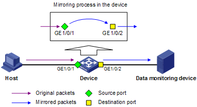
As shown in Figure 1, configure local port mirroring to copy inbound packets on the source port GigabitEthernet 1/0/1 to the monitor port GigabitEthernet 1/0/2, which then forwards the packets to the data monitoring device for analysis.
Remote port mirroring
In remote port mirroring, the source device is not directly connected to the data monitoring device but copies mirrored packets to the destination device, which forwards them to the data monitoring device. The mirroring source and the mirroring destination are on different devices and in different mirroring groups. The mirroring group containing the mirroring source or the mirroring destination is called a "remote source group" or "remote destination group", respectively. The devices between the source devices and destination device are intermediate devices.
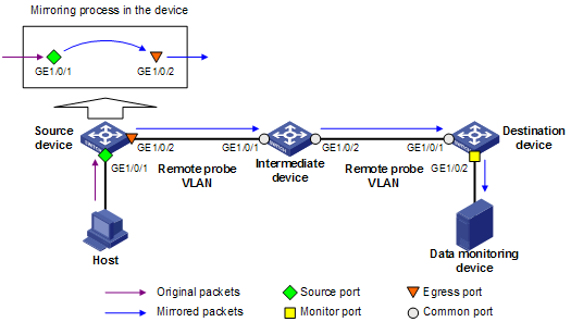
The WX5540E switching engine supports Layer 2 remote port mirroring. In Layer 2 remote port mirroring, the mirroring source and the mirroring destination are on different devices on one Layer 2 network.
The source device copies packets received on the source port to the egress port. The egress port forwards the packets to the intermediate devices, which then broadcast the packets in the remote probe VLAN and transmit the packets to the destination device. When it receives the mirrored packets, the destination device checks whether their VLAN IDs are the same as the remote probe VLAN ID. If yes, the device forwards the packets to the data monitoring device through the monitor port.
Figure 2 Layer 2 remote port mirroring implementation
When you configure Layer 2 remote mirroring, follow these guidelines:
· To make sure that the source device and the destination device can communicate at Layer 2 through the remote probe VLAN, assign the intermediate devices’ ports on the way between the source and destination devices to the remote probe VLAN.
· For a mirrored packet to successfully arrive at the remote destination device, make sure the VLAN ID of the mirrored packet is not removed or changed. Otherwise, the Layer 2 remote port mirroring configuration will fail.
· To monitor both the received and sent packets of a port in a mirroring group, you must use the mac-address mac-learning disable command on the source, intermediate, and destination devices to disable MAC address learning of the remote probe VLAN. For more information about the mac-address mac-learning disable command, see Layer 2—LAN Switch Command Reference.
|
|
NOTE: Both Layer 2 and Layer 3 Ethernet interfaces support the port mirroring function. The term "interface" in this chapter collectively refers to these two types of interfaces. You can use the port link-mode command to configure an Ethernet port as a Layer 2 or Layer 3 interface (see Layer 2—LAN Switching Configuration Guide). |
Configuring local port mirroring
This section describes the local port mirroring configuration procedures.
Local port mirroring configuration task list
Local port mirroring takes effect only when the source ports and the monitor port are configured.
Complete these tasks to configure local port mirroring:
|
Task |
Remarks |
|
Required. |
|
|
Perform at least one configuration. |
|
|
Required. |
|
|
Using the remote probe VLAN to enable local mirroring to support multiple monitor ports |
Optional. |
Creating a local mirroring group
|
Step |
Command |
Remarks |
|
1. Enter system view. |
system-view |
N/A |
|
2. Create a local mirroring group. |
mirroring-group group-id local |
No local mirroring group exists by default. |
Configuring source ports for a local mirroring group
Either you can configure a list of source ports for a mirroring group in system view, or you can assign only the current port to the mirroring group as a source port in interface view. To assign multiple ports to the mirroring group as source ports in interface view, repeat the operation.
Configuration restrictions and guidelines
· A mirroring group can contain multiple source ports.
· On the WX5540E switching engine, one mirroring resource is used for mirroring unidirectional traffic on a source port and two mirroring resources are used for mirroring bidirectional traffic on a source port. A source port on the WX5540E switching engine is assigned a maximum of four mirroring resources. Therefore, a port, when serving as a unidirectional source port, can be added to up to four mirroring groups. When serving as a bidirectional port can be added to up to two mirroring groups, and when serving as a bidirectional source port and two unidirectional ports can be added to up to three mirroring groups.
Configuring source ports in system view
|
Step |
Command |
Remarks |
|
1. Enter system view. |
system-view |
N/A |
|
2. Configure source ports for a local mirroring group. |
mirroring-group group-id mirroring-port mirroring-port-list { both | inbound | outbound } |
By default, no source port is configured for a local mirroring group. |
Configuring a source port in interface view
|
Step |
Command |
Remarks |
|
1. Enter system view. |
system-view |
N/A |
|
2. Enter interface view. |
interface interface-type interface-number |
N/A |
|
3. Configure the current port as a source port for a local mirroring group. |
[ mirroring-group group-id ] mirroring-port { both | inbound | outbound } |
By default, a port does not serve as a source port for any local mirroring group. |
Configuring source CPUs for a local mirroring group
|
Step |
Command |
Remarks |
|
1. Enter system view. |
system-view |
N/A |
|
2. Configure source CPUs for a local mirroring group. |
mirroring-group group-id mirroring-cpu slot slot-number-list { both | inbound | outbound } |
By default, no source CPU is configured for a local mirroring group. |
Configuring the monitor port for a local mirroring group
|
|
CAUTION: Do not enable the spanning tree feature on the monitor port. |
Either you can configure the monitor port for a mirroring group in system view, or you can assign the current port to a mirroring group as the monitor port in interface view. The two modes lead to the same result.
Configuration restrictions and guidelines
· A mirroring group contains only one monitor port.
· H3C recommends that you use a monitor port for port mirroring only. This is to make sure that the data monitoring device receives and analyzes only the mirrored traffic rather than a mix of mirrored traffic and normally forwarded traffic.
· You cannot configure the monitor port in a mirroring group as a port in an RRPP ring.
Configuring the monitor port in system view
|
Step |
Command |
Remarks |
|
1. Enter system view. |
system-view |
N/A |
|
2. Configure the monitor port for a local mirroring group. |
mirroring-group group-id monitor-port monitor-port-id |
By default, no monitor port is configured for a local mirroring group. |
Configuring the monitor port in interface view
|
Step |
Command |
Remarks |
|
1. Enter system view. |
system-view |
N/A |
|
2. Enter interface view. |
interface interface-type interface-number |
N/A |
|
3. Configure the current port as the monitor port for a local mirroring group. |
[ mirroring-group group-id ] monitor-port |
By default, a port does not serve as the monitor port for any local mirroring group. |
Using the remote probe VLAN to enable local mirroring to support multiple monitor ports
In typical local port mirroring configuration, you can configure only one monitor port in a local mirroring group. As a result, you cannot monitor traffic of a local device on multiple data monitoring devices. To do that, take advantage of the remote probe VLAN used in Layer 2 remote mirroring.
In Layer 2 remote port mirroring, a remote probe VLAN is configured, and the mirrored packets are broadcast within the remote probe VLAN. By connecting multiple data monitoring devices to the remote probe VLAN's member ports, you can monitor the local device's traffic on multiple data monitoring devices.
Configure this feature by following these steps:
1. Configure a remote source mirroring group on the local device.
2. Configure the monitored ports on the device as source ports of this mirroring group.
3. Configure a remote probe VLAN for this mirroring group.
4. Assign the ports connecting the data monitoring devices to the remote probe VLAN.
In this way, when packets mirrored on the monitored ports are broadcast in the remote probe VLAN, they are sent out of the ports connecting the data monitoring devices, and all data monitoring devices can thus receive these mirrored packets.
Configuration restrictions and guidelines
· The reflector port of a remote source mirroring group must be an access port and belong to the default VLAN, VLAN 1.
· H3C recommends that you configure an unused port as the reflector port of a remote source mirroring group and disable spanning tree on it.
· Do not configure a combo interface as a reflector port.
· A mirroring group can contain multiple source ports.
· To make sure that the port mirroring function works properly, do not assign a source port to the remote probe VLAN.
· If you have already configured a reflector port for a remote source mirroring group, you can no longer configure an egress port for it.
· A VLAN can serve as the remote probe VLAN for only one remote source mirroring group. H3C recommends that you use the remote probe VLAN for port mirroring exclusively. Do not create a VLAN interface for the VLAN or configure any other features for the VLAN.
· A remote probe VLAN must be a static VLAN. To remove the VLAN configured as a remote probe VLAN, you must first remove the remote probe VLAN with the undo mirroring-group remote-probe vlan command.
· If the remote probe VLAN of a remote mirroring group is removed, the remote mirroring group will become invalid.
· The link type of monitor ports configured for port mirroring must be access.
Configuration procedure
To configure local port mirroring with multiple monitor ports:
|
Step |
Command |
Remarks |
|
1. Enter system view. |
system-view |
N/A |
|
2. Create a remote source mirroring group. |
mirroring-group group-id remote-source |
By default, no mirroring group exists on a device. |
|
3. Configure source ports for the remote source mirroring group. |
·
(Method 1) In system
view: · (Method 2) In interface view: a. interface interface-type interface-number b. [ mirroring-group group-id ] mirroring-port { both | inbound | outbound } c. quit |
Use either method. By default, no source port is configured for a mirroring group. |
|
4. Configure the reflector port for the remote source mirroring group. |
mirroring-group group-id reflector-port reflector-port |
By default, no reflector port is configured for a mirroring group. |
|
5. Create the remote probe VLAN and enter VLAN view. |
vlan vlan-id |
By default, no remote probe VLAN is configured for a mirroring group. |
|
6. Assign monitor ports to the remote probe VLAN. |
port interface-list |
By default, a newly-created VLAN does not have any member port. |
|
7. Return to system view. |
quit |
N/A |
|
8. Configure the remote probe VLAN for the remote source mirroring group. |
mirroring-group group-id remote-probe vlan rprobe-vlan-id |
By default, no remote probe VLAN is configured for a mirroring group. |
Configuring Layer 2 remote port mirroring
This section describes the Layer 2 remote port mirroring configuration procedures.
Layer 2 remote port mirroring configuration task list
|
|
CAUTION: For a mirrored packet to successfully arrive at the remote destination device, make sure the VLAN ID of the mirrored packet is not removed or changed. |
To configure Layer 2 remote port mirroring, configure remote mirroring groups. When doing that, configure the remote source group on the source device, and configure the cooperating remote destination group on the destination device. If an intermediate device exists, configure the intermediate devices to allow the remote probe VLAN to pass through.
H3C recommends that you not enable GARP VLAN Registration Protocol (GVRP). If GVRP is enabled, GVRP may register the remote probe VLAN to unexpected ports, resulting in undesired duplicates. For more information about GVRP, see Layer 2—LAN Switching Configuration Guide.
Do the following to configure Layer 2 remote port mirroring:
· On the source device, configure the source ports/CPUs, the remote probe VLAN, and the egress port for the remote source group.
· On the destination device, configure the remote probe VLAN and the monitor port for the remote destination group.
Complete these tasks to configure Layer 2 remote port mirroring:
|
Task |
Remarks |
|
|
Configuring a remote source group |
Required. |
|
|
Perform at least one configuration. |
||
|
Required. |
||
|
Required. |
||
|
Configuring a remote destination group |
Required. |
|
|
Required. |
||
|
Configuring the remote probe VLAN for a remote destination group |
Required. |
|
|
Required. |
||
Configuring a remote source group (on the source device)
This section describes how to configure a remote source group on the source device.
Creating a remote source group
|
Step |
Command |
Remarks |
|
1. Enter system view. |
system-view |
N/A |
|
2. Create a remote source group. |
mirroring-group group-id remote-source |
By default, no remote source group exists on a device. |
Configuring source ports for a remote source group
|
|
CAUTION: Do not assign a source port to the remote probe VLAN. |
Either you can configure a list of source ports for a mirroring group in system view, or you can assign only the current port to the a mirroring group as a source port in interface view. To assign multiple ports to the mirroring group as source ports in interface view, repeat the step.
When you configure source ports for the remote source group, follow these guidelines:
· A mirroring group can contain multiple source ports.
· On the WX5540E switching engine, one mirroring resource is used for mirroring unidirectional traffic on a source port and two mirroring resources are used for mirroring bidirectional traffic on a source port. A source port on the WX5540E switching engine is assigned a maximum of four mirroring resources. Therefore, a port, when serving as a unidirectional source port, can be added to up to four mirroring groups. When serving as a bidirectional port can be added to up to two mirroring groups, and when serving as a bidirectional source port and two unidirectional ports can be added to up to three mirroring groups.
To configure source ports for a remote source group in system view:
|
Step |
Command |
Remarks |
|
1. Enter system view. |
system-view |
N/A |
|
2. Configure source ports for a remote source group. |
mirroring-group group-id mirroring-port mirroring-port-list { both | inbound | outbound } |
By default, no source port is configured for a remote source group. |
To configure a source port for a remote source group in interface view:
|
Step |
Command |
Remarks |
|
1. Enter system view. |
system-view |
N/A |
|
2. Enter interface view. |
interface interface-type interface-number |
N/A |
|
3. Configure the current port as a source port for a remote source group. |
[ mirroring-group group-id ] mirroring-port { both | inbound | outbound } |
By default, a port does not serve as a source port for any remote source group. |
Configuring source CPUs for a remote source group
|
Step |
Command |
Remarks |
|
1. Enter system view. |
system-view |
N/A |
|
2. Configure source CPUs for a remote source group. |
mirroring-group group-id mirroring-cpu slot slot-number-list { both | inbound | outbound } |
By default, no source CPU is configured for a remote source group. |
Configuring the egress port for a remote source group
|
|
CAUTION: Disable these functions on the egress port: spanning tree, 802.1X, IGMP snooping, static ARP, and MAC address learning. |
Either you can configure the egress port for a mirroring group in system view, or you can assign the current port to it as the egress port in interface view. The two configuration methods lead to the same result.
When you configure the egress port for the remote source group, follow these guidelines:
· A mirroring group contains only one egress port.
· A port of an existing mirroring group cannot be configured as an egress port.
To configure the egress port for a remote source group in system view:
|
Step |
Command |
Remarks |
|
1. Enter system view. |
system-view |
N/A |
|
2. Configure the egress port for a remote source group. |
mirroring-group group-id monitor-egress monitor-egress-port |
By default, no egress port is configured for a remote source group. |
To configure the egress port for a remote source group in interface view:
|
Step |
Command |
Remarks |
|
1. Enter system view. |
system-view |
N/A |
|
2. Enter interface view. |
interface interface-type interface-number |
N/A |
|
3. Configure the current port as the egress port for a remote source group. |
mirroring-group group-id monitor-egress |
By default, a port does not serve as the egress port for any remote source group. |
Configuring the remote probe VLAN for a remote source group
Before configuring a remote probe VLAN, create a static VLAN that serves as the remote probe VLAN for the remote source group.
When you configure the remote probe VLAN for the remote source group, follow these guidelines:
· A VLAN can serve for only one mirroring group.
· When a VLAN is configured as a remote probe VLAN, you must remove the remote probe VLAN configuration before deleting the VLAN.
· When you remove the configuration of a remote probe VLAN, an active mirroring group becomes inactive.
· When a VLAN is configured as a remote probe VLAN, use the remote probe VLAN for port mirroring exclusively. Do not configure a VLAN interface or any other features for the VLAN.
· The remote mirroring groups on the source device and destination device must use the same remote probe VLAN.
To configure the remote probe VLAN for a remote source group:
|
Step |
Command |
Remarks |
|
1. Enter system view. |
system-view |
N/A |
|
2. Configure the remote probe VLAN. |
mirroring-group group-id remote-probe vlan rprobe-vlan-id |
By default, no remote probe VLAN is configured for a remote source group. |
Configuring a remote destination group (on the destination device)
To configure a remote destination group, make the following configurations on the destination device:
Creating a remote destination group
|
Step |
Command |
Remarks |
|
1. Enter system view. |
system-view |
N/A |
|
2. Create a remote destination group. |
mirroring-group group-id remote-destination |
By default, no remote destination group exists on a device. |
Configuring the monitor port for a remote destination group
Either you can configure the monitor port for a mirroring group in system view, or you can assign the current port to a mirroring group as the monitor port in interface view. The two methods lead to the same result.
When you configure the monitor port for the remote destination group, follow these guidelines:
· Do not enable the spanning tree feature on the monitor port.
· H3C recommends that you use a monitor port only for port mirroring. This is to make sure that the data monitoring device receives and analyzes only the mirrored traffic rather than a mix of mirrored traffic and normally forwarded traffic.
· You cannot configure the monitor port in a mirroring group as a port in an RRPP ring.
· A mirroring group contains only one monitor port.
To configure the monitor port for a remote destination group in system view:
|
Step |
Command |
Remarks |
|
1. Enter system view. |
system-view |
N/A |
|
2. Configure the monitor port. |
mirroring-group group-id monitor-port monitor-port-id |
By default, no monitor port is configured for a remote destination group. |
To configure the monitor port for a remote destination group in interface view:
|
Step |
Command |
Remarks |
|
1. Enter system view. |
system-view |
N/A |
|
2. Enter interface view. |
interface interface-type interface-number |
N/A |
|
3. Configure the current port as the monitor port for a remote destination group. |
[ mirroring-group group-id ] monitor-port |
By default, a port does not serve as the monitor port for any remote destination group. |
Configuring the remote probe VLAN for a remote destination group
When you configure the remote probe VLAN for the remote destination group, follow these guidelines:
· A VLAN can serve for only one mirroring group.
· When a VLAN is configured as a remote probe VLAN, use the remote probe VLAN for port mirroring exclusively. Do not configure a VLAN interface or any other features for the VLAN.
· When a VLAN is configured as a remote probe VLAN, you must remove the remote probe VLAN configuration before deleting the VLAN.
· When you remove the configuration of a remote probe VLAN, an active mirroring group becomes inactive.
· Configure the same remote probe VLAN for the remote destination group on the source device and destination device.
To configure the remote probe VLAN for a remote destination group:
|
Step |
Command |
Remarks |
|
1. Enter system view. |
system-view |
N/A |
|
2. Configure the remote probe VLAN for a remote destination group. |
mirroring-group group-id remote-probe vlan rprobe-vlan-id |
By default, no remote probe VLAN is configured for a remote destination group. |
Assigning the monitor port to the remote probe VLAN
|
Step |
Command |
Remarks |
|
1. Enter system view. |
system-view |
N/A |
|
2. Enter the interface view of the monitor port. |
interface interface-type interface-number |
N/A |
|
3. Assign the port to the probe VLAN. |
·
For an access port: ·
For a trunk port: ·
For a hybrid port: |
Use one of the commands. For more information about the port access vlan, port trunk permit vlan, and port hybrid vlan commands, see Layer 2—LAN Switching Command Reference. |
Displaying and maintaining port mirroring
|
Task |
Command |
Remarks |
|
Display mirroring group information. |
display mirroring-group { group-id | all | local | remote-destination | remote-source } [ | { begin | exclude | include } regular-expression ] |
Available in any view. |
Port mirroring configuration examples
This section provides port mirroring configuration examples.
Local port mirroring configuration example
Network requirements
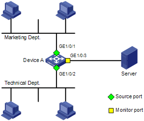
On the network shown in Figure 3:
· Device A connects to the marketing department through GigabitEthernet 1/0/1 and to the technical department through GigabitEthernet 1/0/2. It connects to the server through GigabitEthernet 1/0/3.
· Configure local port mirroring in source port mode to enable the server to monitor the bidirectional traffic of the marketing department and the technical department.
Configuration procedure
# Create local mirroring group 1.
<DeviceA> system-view
[DeviceA] mirroring-group 1 local
# Configure GigabitEthernet 1/0/1 and GigabitEthernet 1/0/2 as source ports, and configure port GigabitEthernet 1/0/3 as the monitor port.
[DeviceA] mirroring-group 1 mirroring-port gigabitethernet 1/0/1 gigabitethernet 1/0/2 both
[DeviceA] mirroring-group 1 monitor-port gigabitethernet 1/0/3
# Disable the spanning tree feature on the monitor port GigabitEthernet 1/0/3.
[DeviceA] interface gigabitethernet 1/0/3
[DeviceA-GigabitEthernet1/0/3] undo stp enable
[DeviceA-GigabitEthernet1/0/3] quit
Verifying the configuration
# Display the configuration of all mirroring groups.
[DeviceA] display mirroring-group all
mirroring-group 1:
type: local
status: active
mirroring port:
GigabitEthernet1/0/1 both
GigabitEthernet1/0/2 both
mirroring CPU:
monitor port: GigabitEthernet1/0/3
After the configurations are completed, you can monitor all packets received and sent by the marketing department and the technical department on the server.
Local port mirroring with multiple monitor ports configuration example
Network requirements
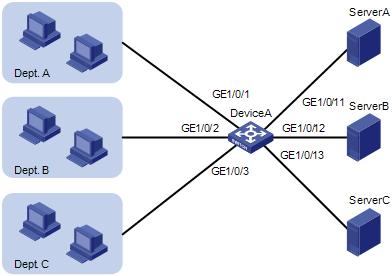
As shown in Figure 4, Dept. A, Dept. B, and Dept. C are connected to Device A through ports GigabitEthernet 1/0/1, GigabitEthernet 1/0/2, and GigabitEthernet 1/0/3, respectively. Configure port mirroring to enable all three data monitoring devices (Server A, Server B, and Server C), to monitor both the incoming and outgoing traffic of the three departments.
Configuration procedure
# Create remote source mirroring group 1.
<DeviceA> system-view
[DeviceA] mirroring-group 1 remote-source
# Configure GigabitEthernet 1/0/1 through GigabitEthernet 1/0/3 as source ports of remote source mirroring group 1.
[DeviceA] mirroring-group 1 mirroring-port gigabitethernet 1/0/1 to gigabitethernet 1/0/3 both
# Configure an unused port (GigabitEthernet 1/0/5, for example) of Device A as the reflector port of remote source mirroring group 1.
[DeviceA] mirroring-group 1 reflector-port gigabitethernet 1/0/5
# Create VLAN 10 and assign the three ports (GigabitEthernet 1/0/11 through GigabitEthernet 1/0/13) connecting the three data monitoring devices to VLAN 10.
[DeviceA] vlan 10
[DeviceA-vlan10] port gigabitethernet 1/0/11 to gigabitethernet 1/0/13
[DeviceA-vlan10] quit
# Configure VLAN 10 as the remote probe VLAN of remote source mirroring group 1.
[DeviceA] mirroring-group 1 remote-probe vlan 10
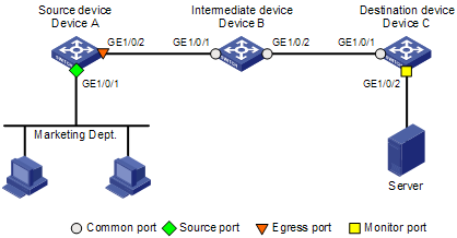
Layer 2 remote port mirroring configuration example
Network requirements
As shown in Figure 5, configure Layer 2 remote port mirroring to enable the server to monitor the bidirectional traffic of the marketing department.
Configuration procedure
1. Configure Device A (the source device):
# Create a remote source group.
<DeviceA> system-view
[DeviceA] mirroring-group 1 remote-source
# Create VLAN 2.
[DeviceA] vlan 2
# Disable MAC address learning for VLAN 2.
[DeviceA-vlan2] mac-address mac-learning disable
[DeviceA-vlan2] quit
# Configure VLAN 2 as the remote probe VLAN of the mirroring group. Configure GigabitEthernet 1/0/1 as a source port and GigabitEthernet 1/0/2 as the egress port in the mirroring group.
[DeviceA] mirroring-group 1 remote-probe vlan 2
[DeviceA] mirroring-group 1 mirroring-port gigabitethernet 1/0/1 both
[DeviceA] mirroring-group 1 monitor-egress gigabitethernet 1/0/2
# Configure output port GigabitEthernet 1/0/2 as a trunk port to permit the packets from VLAN 2 to pass through, and disable the spanning tree feature on the port.
[DeviceA] interface gigabitethernet 1/0/2
[DeviceA-GigabitEthernet1/0/2] port link-type trunk
[DeviceA-GigabitEthernet1/0/2] port trunk permit vlan 2
[DeviceA-GigabitEthernet1/0/2] undo stp enable
[DeviceA-GigabitEthernet1/0/2] quit
2. Configure Device B (the intermediate device):
# Create VLAN 2 as the remote probe VLAN.
<DeviceB> system-view
[DeviceB] vlan 2
# Disable MAC address learning for the remote probe VLAN.
[DeviceB-vlan2] mac-address mac-learning disable
[DeviceB-vlan2] quit
# Configure GigabitEthernet 1/0/1 as a trunk port that permits the packets from VLAN 2 to pass through.
[DeviceB] interface gigabitethernet 1/0/1
[DeviceB-GigabitEthernet1/0/1] port link-type trunk
[DeviceB-GigabitEthernet1/0/1] port trunk permit vlan 2
[DeviceB-GigabitEthernet1/0/1] quit
# Configure GigabitEthernet 1/0/2 as a trunk port that permits the packets from VLAN 2 to pass through.
[DeviceB] interface gigabitethernet 1/0/2
[DeviceB-GigabitEthernet1/0/2] port link-type trunk
[DeviceB-GigabitEthernet1/0/2] port trunk permit vlan 2
[DeviceB-GigabitEthernet1/0/2] quit
3. Configure Device C (the destination device):
# Configure GigabitEthernet 1/0/1 as a trunk port that permits the packets from VLAN 2 to pass through.
<DeviceC> system-view
[DeviceC] interface gigabitethernet 1/0/1
[DeviceC-GigabitEthernet1/0/1] port link-type trunk
[DeviceC-GigabitEthernet1/0/1] port trunk permit vlan 2
[DeviceC-GigabitEthernet1/0/1] quit
# Create a remote destination group.
[DeviceC] mirroring-group 1 remote-destination
# Create VLAN 2.
[DeviceC] vlan 2
# Disable MAC address learning for VLAN 2.
[DeviceC-vlan2] mac-address mac-learning disable
[DeviceC-vlan2] quit
# Configure VLAN 2 as the remote probe VLAN of the mirroring group and GigabitEthernet1/0/2 as the monitor port of the mirroring group, disable the spanning tree feature on GigabitEthernet1/0/2, and assign the port to VLAN 2.
[DeviceC] mirroring-group 1 remote-probe vlan 2
[DeviceC] interface gigabitethernet 1/0/2
[DeviceC-GigabitEthernet1/0/2] mirroring-group 1 monitor-port
[DeviceC-GigabitEthernet1/0/2] undo stp enable
[DeviceC-GigabitEthernet1/0/2] port access vlan 2
[DeviceC-GigabitEthernet1/0/2] quit
Verifying the configuration
After the configurations are completed, you can monitor all packets received and sent by the marketing department on the server.