- Table of Contents
- Related Documents
-
| Title | Size | Download |
|---|---|---|
| 02-NTP configuration | 397.64 KB |
Configuring NTP operation modes
Configuring the client/server mode
Configuring the symmetric peers mode·
Configuring the broadcast mode
Configuring the multicast mode
Configuring optional parameters
Specifying the source interface for NTP messages
Disabling an interface from receiving NTP messages
Configuring the allowed maximum number of dynamic sessions
Configuring the DSCP value for NTP messages
Configuring access-control rights
Configuring NTP authentication
Configuring NTP authentication in client/server mode
Configuring NTP authentication in symmetric peers mode
Configuring NTP authentication in broadcast mode
Configuring NTP authentication in multicast mode
Displaying and maintaining NTP
NTP client/server mode configuration example
NTP symmetric peers mode configuration example
NTP broadcast mode configuration example
NTP multicast mode configuration example
Configuration example for NTP client/server mode with authentication
Configuration example for NTP broadcast mode with authentication
This chapter provides an overview of NTP configuration.
Overview
NTP is typically used in large networks to dynamically synchronize time among network devices. It guarantees higher clock accuracy than manual system clock setting. In a small network that does not require high clock accuracy, you can keep time synchronized among devices by changing their system clocks one by one.
NTP runs over UDP and uses UDP port 123.
NTP application
An administrator is unable to keep time synchronized among all devices within a network by changing the system clock on each station, because this is a huge work and does not guarantee clock precision. NTP, however, allows quick clock synchronization within the entire network and ensures high clock precision.
NTP is used when all devices within the network must keep consistent time. For example:
· In analyzing log and debugging information collected from different devices in network management, time must be used as a reference basis.
· All devices must use the same reference clock in a charging system.
· To implement certain functions, such as a scheduled restart of all devices within the network, all devices must keep consistent time.
· If multiple systems process a complex event in cooperation, these systems must use the same reference clock to ensure the correct execution sequence.
· For incremental backup between a backup server and clients, timekeeping must be synchronized between the backup server and all clients.
NTP advantages
· NTP uses a stratum to describe clock accuracy. The stratum ranges from 1 to 16. Clock accuracy decreases as the stratum number increases. The stratum of a reference clock ranges from 1 to 15. A stratum 16 clock is in unsynchronized state.
· NTP supports access control and MD5 authentication.
· NTP can unicast, multicast, or broadcast protocol messages.
How NTP works
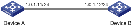
Figure 1 shows the basic workflow of NTP. Device A and Device B are connected over a network. They have their own independent system clocks, which need to be automatically synchronized through NTP. Assume that:
· Prior to system clock synchronization between Device A and Device B, the clock of Device A is set to 10:00:00 am while that of Device B is set to 11:00:00 am.
· Device B is used as the NTP time server, so Device A synchronizes to Device B.
· It takes 1 second for an NTP message to travel from one device to the other.
Figure 1 Basic work flow of NTP
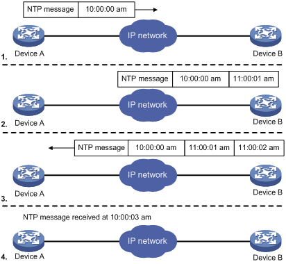
The synchronization process is as follows:
· Device A sends Device B an NTP message, which is timestamped when it leaves Device A. The timestamp is 10:00:00 am (T1).
· When this NTP message arrives at Device B, it is timestamped by Device B. The timestamp is 11:00:01 am (T2).
· When the NTP message leaves Device B, Device B timestamps it. The timestamp is 11:00:02 am (T3).
· When Device A receives the NTP message, the local time of Device A is 10:00:03 am (T4).
Up to now, Device A can calculate the following parameters based on the timestamps:
· The roundtrip delay of NTP message: Delay = (T4–T1) – (T3-T2) = 2 seconds.
· Time difference between Device A and Device B: Offset = ((T2-T1) + (T3-T4))/2 = 1 hour.
Based on these parameters, Device A can synchronize its own clock to the clock of Device B.
This is a rough description of how NTP works. For more information, see RFC 1305.
NTP message format
NTP uses two types of messages: clock synchronization and NTP control messages. All NTP messages mentioned in this document refer to NTP clock synchronization messages. NTP control messages are used in environments where network management is needed. Because NTP control messages are not essential for clock synchronization, they are not described in this document.
A clock synchronization message is encapsulated in a UDP message in the format shown in Figure 2.
Figure 2 Clock synchronization message format
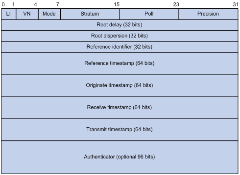
The main fields are described as follows:
· LI (Leap Indicator)—A 2-bit leap indicator. If set to 11, it warns of an alarm condition (clock unsynchronized). If set to any other value, it is not to be processed by NTP.
· VN (Version Number)—A 3-bit version number that indicates the version of NTP. The latest version is version 4.
· Mode—A 3-bit code that indicates the operation mode of NTP. This field can be set to these values:
¡ 0—Reserved.
¡ 1—Symmetric active.
¡ 2—Symmetric passive.
¡ 3—Client.
¡ 4—Server.
¡ 5—Broadcast or multicast.
¡ 6—NTP control message.
¡ 7—Reserved for private use.
· Stratum—An 8-bit integer that indicates the stratum level of the local clock, with the value ranging from 1 to 16. Clock precision decreases from stratum 1 through stratum 16. A stratum 1 clock has the highest precision, and a stratum 16 clock is not synchronized.
· Poll—An 8-bit signed integer that indicates the maximum interval between successive messages, which is called the poll interval.
· Precision—An 8-bit signed integer that indicates the precision of the local clock.
· Root Delay—Roundtrip delay to the primary reference source.
· Root Dispersion—The maximum error of the local clock relative to the primary reference source.
· Reference Identifier—Identifier of the particular reference source.
· Reference Timestamp—The local time at which the local clock was last set or corrected.
· Originate Timestamp—The local time at which the request departed from the client for the service host.
· Receive Timestamp—The local time at which the request arrived at the service host.
· Transmit Timestamp—The local time at which the reply departed from the service host for the client.
· Authenticator—Authentication information.
Operation modes
Devices that run NTP can implement clock synchronization in one of the following modes:
· Client/server mode
· Symmetric peers mode
· Broadcast mode
· Multicast mode
You can select operation modes of NTP as needed. If the IP address of the NTP server or peer is unknown and many devices in the network need to be synchronized, adopt the broadcast or multicast mode. In the client/server or symmetric peers mode, a device is synchronized from the specified server or peer, so clock reliability is enhanced.
Client/server mode
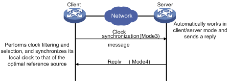
When operating in client/server mode, a client sends a clock synchronization message to servers with the Mode field in the message set to 3 (client mode). Upon receiving the message, the servers automatically operate in server mode and send a reply, with the Mode field in the messages set to 4 (server mode). Upon receiving the replies from the servers, the client performs clock filtering and selection and synchronizes to the optimal reference source.
In client/server mode, a client can synchronize to a server, but a server cannot synchronize to a client.
Symmetric peers mode
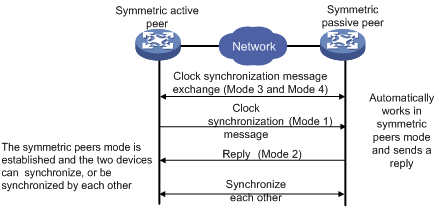
In symmetric peers mode, devices that operate in symmetric active mode and symmetric passive mode exchange NTP messages with the Mode field 3 (client mode) and 4 (server mode). Then the device that operates in symmetric active mode periodically sends clock synchronization messages, with the Mode field in the messages set to 1 (symmetric active). The device that receives the messages automatically enters symmetric passive mode and sends a reply, with the Mode field in the message set to 2 (symmetric passive). This exchange of messages establishes symmetric peers mode between the two devices, so the two devices can synchronize, or be synchronized by, each other. If the clocks of both devices have been synchronized, the device whose local clock has a lower stratum level synchronizes the other device.
Broadcast mode
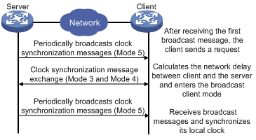
In broadcast mode, a server periodically sends clock synchronization messages to broadcast address 255.255.255.255, with the Mode field in the messages set to 5 (broadcast mode). Clients listen to the broadcast messages from servers. When a client receives the first broadcast message, the client and the server start to exchange messages with the Mode field set to 3 (client mode) and 4 (server mode), to calculate the network delay between client and the server. Then, the client enters broadcast client mode. The client continues listening to broadcast messages, and synchronizes its local clock based on the received broadcast messages.
Multicast mode
Figure 6 Multicast mode

In multicast mode, a server periodically sends clock synchronization messages to the user-configured multicast address, or, if no multicast address is configured, to the default NTP multicast address 224.0.1.1, with the Mode field in the messages set to 5 (multicast mode). Clients listen to the multicast messages from servers. When a client receives the first multicast message, the client and the server start to exchange messages with the Mode field set to 3 (client mode) and 4 (server mode), to calculate the network delay between client and server. Then, the client enters multicast client mode. It continues listening to multicast messages, and synchronizes its local clock based on the received multicast messages.
In symmetric peers mode, broadcast mode, and multicast mode, the client (or the symmetric active peer) and the server (the symmetric passive peer) can operate in the specified NTP operation mode only after they exchange NTP messages with the Mode field 3 (client mode) and the Mode field 4 (server mode). During this message exchange process, NTP clock synchronization can be implemented.
NTP configuration task list
|
Task |
Remarks |
|
Required. |
|
|
Optional. |
|
|
Optional. |
|
|
Optional. |
Configuring NTP operation modes
Devices can implement clock synchronization in one of the following modes:
· Client/server mode—Configure only clients.
· Symmetric mode—Configure only symmetric-active peers.
· Broadcast mode—Configure both clients and servers.
· Multicast mode—Configure both clients and servers.
Configuring the client/server mode
For devices operating in client/server mode, make configurations on the clients.
If you specify the source interface for NTP messages by specifying the source interface source-interface option, NTP uses the primary IP address of the specified interface as the source IP address of the NTP messages.
A device can act as a server to synchronize other devices only after it is synchronized. If a server has a stratum level higher than or equal to a client, the client will not synchronize to that server.
To specify an NTP server on the client:
|
Step |
Command |
Remarks |
|
1. Enter system view. |
system-view |
N/A |
|
2. Specify an NTP server for the device. |
ntp-service unicast-server { ip-address | server-name } [ authentication-keyid keyid | priority | source-interface interface-type interface-number | version number ] * |
By default, no NTP server is specified. In this command, the ip-address argument must be a unicast address, rather than a broadcast address, a multicast address or the IP address of the local clock. You can configure multiple servers by repeating the command. The clients will select the optimal reference source. |
Configuring the symmetric peers mode
Follow these guidelines when you configure the NTP symmetric peers mode:
· For devices operating in symmetric mode, specify a symmetric-passive peer on a symmetric-active peer.
· Use any NTP configuration command in "Configuring NTP operation modes" to enable NTP. Otherwise, a symmetric-passive peer does not process NTP messages from a symmetric-active peer.
· Either the symmetric-active peer or the symmetric-passive peer must be in synchronized state. Otherwise, clock synchronization does not proceed.
To specify a symmetric-passive peer on the active peer:
|
Step |
Command |
Remarks |
|
1. Enter system view. |
system-view |
N/A |
|
2. Specify a symmetric-passive peer for the device. |
ntp-service unicast-peer { ip-address | peer-name } [ authentication-keyid keyid | priority | source-interface interface-type interface-number | version number ] * |
By default, no symmetric-passive peer is specified. The ip-address argument must be a unicast address, rather than a broadcast address, a multicast address, or the IP address of the local clock. After you specify the source interface for NTP messages by specifying the source interface source-interface option, the source IP address of the NTP messages is set as the primary IP address of the specified interface. You can configure multiple symmetric-passive peers by repeating this command. |
Configuring the broadcast mode
The broadcast server periodically sends NTP broadcast messages to the broadcast address 255.255.255.255. After receiving the messages, the device operating in NTP broadcast client mode sends a reply and synchronizes to the server.
Configure the NTP broadcast mode on both the server and clients. The NTP broadcast mode can only be configured in a specific interface view because an interface needs to be specified on the broadcast server for sending NTP broadcast messages and on each broadcast client for receiving broadcast messages.
Configuring a broadcast client
|
Step |
Command |
Remarks |
|
1. Enter system view. |
system-view |
N/A |
|
2. Enter VLAN interface view. |
interface interface-type interface-number |
This command enters the view of the interface for sending NTP broadcast messages. |
|
3. Configure the device to operate in NTP broadcast client mode. |
ntp-service broadcast-client |
N/A |
Configuring the broadcast server
|
Step |
Command |
Remarks |
|
1. Enter system view. |
system-view |
N/A |
|
2. Enter VLAN interface view. |
interface interface-type interface-number |
This command enters the view of the interface for sending NTP broadcast messages. |
|
3. Configure the device to operate in NTP broadcast server mode. |
ntp-service broadcast-server [ authentication-keyid keyid | version number ] * |
A broadcast server can synchronize broadcast clients only when its clock has been synchronized. |
Configuring the multicast mode
The multicast server periodically sends NTP multicast messages to multicast clients, which send replies after receiving the messages and synchronize their local clocks.
Configure the NTP multicast mode on both the server and clients. The NTP multicast mode must be configured in a specific interface view.
Configuring a multicast client
|
Step |
Command |
Remarks |
|
1. Enter system view. |
system-view |
N/A |
|
2. Enter VLAN interface view. |
interface interface-type interface-number |
This command enters the view of the interface for sending NTP multicast messages. |
|
3. Configure the device to operate in NTP multicast client mode. |
ntp-service multicast-client [ ip-address ] |
N/A |
Configuring the multicast server
|
Step |
Command |
Remarks |
|
1. Enter system view. |
system-view |
N/A |
|
2. Enter VLAN interface view. |
interface interface-type interface-number |
This command enters the view of the interface for sending NTP multicast messages. |
|
3. Configure the device to operate in NTP multicast server mode. |
ntp-service multicast-server [ ip-address ] [ authentication-keyid keyid | ttl ttl-number | version number ] * |
A multicast server can synchronize broadcast clients only when its clock has been synchronized. |
Configuring optional parameters
This section explains how to configure the optional parameters of NTP.
Specifying the source interface for NTP messages
If you specify the source interface for NTP messages, the device sets the source IP address of the NTP messages as the primary IP address of the specified interface when sending the NTP messages.
When the device responds to an NTP request received, the source IP address of the NTP response is always the IP address of the interface that received the NTP request.
Configuration guidelines
· The source interface for NTP unicast messages is the interface specified in the ntp-service unicast-server or ntp-service unicast-peer command.
· The source interface for NTP broadcast or multicast messages is the interface where you configure the ntp-service broadcast-server or ntp-service multicast-server command.
· If the specified source interface goes down, NTP uses the primary IP address of the outgoing interface as the source IP address.
Configuration procedure
To specify the source interface for NTP messages:
|
Step |
Command |
Remarks |
|
1. Enter system view. |
system-view |
N/A |
|
2. Specify the source interface for NTP messages. |
ntp-service source-interface interface-type interface-number |
By default, no source interface is specified for NTP messages, and the system uses the IP address of the interface determined by the matching route as the source IP address of NTP messages. |
Disabling an interface from receiving NTP messages
If NTP is enabled, NTP messages can be received from all interfaces by default. You can disable an interface from receiving NTP messages by using the following configuration.
|
Step |
Command |
Remarks |
|
1. Enter system view. |
system-view |
N/A |
|
2. Enter VLAN interface view. |
interface interface-type interface-number |
N/A |
|
3. Disable the interface from receiving NTP messages. |
ntp-service in-interface disable |
By default, an interface is enabled to receive NTP messages. |
Configuring the allowed maximum number of dynamic sessions
NTP has the following types of associations:
· Static association—An association that a user has manually created by using an NTP command.
· Dynamic association—Temporary association created by the system during operation. A dynamic association is removed if the system fails to receive messages from it over a specific period of time.
The following describes how an association is established in different operation modes:
· Client/server mode—After you specify an NTP server, the system creates a static association on the client. The server simply responds passively upon the receipt of a message, rather than creating an association (static or dynamic).
· Symmetric active/passive mode—After you specify a symmetric-passive peer on a symmetric active peer, static associations are created on the symmetric-active peer, and dynamic associations are created on the symmetric-passive peer.
· Broadcast or multicast mode—Static associations are created on the server, and dynamic associations are created on the client.
A single device can have a maximum of 128 concurrent associations, including static associations and dynamic associations.
To configure the allowed maximum number of dynamic sessions:
|
Step |
Command |
Remarks |
|
1. Enter system view. |
system-view |
N/A |
|
2. Configure the maximum number of dynamic sessions allowed to be established locally. |
ntp-service max-dynamic-sessions number |
The default is 100. |
Configuring the DSCP value for NTP messages
|
Step |
Command |
Remarks |
|
1. Enter system view. |
system-view |
N/A |
|
2. Configure the Differentiated Service Code Point (DSCP) value for NTP messages. |
ntp-service dscp dscp-value |
Optional. The default setting is 16. |
Configuring access-control rights
From the highest to lowest, the NTP service access-control rights are peer, server, synchronization, and query. If a device receives an NTP request, it performs an access-control right match and uses the first matched right. If no matched right is found, the device drops the NTP request.
· Query—Control query permitted. This level of right permits the peer devices to perform control query to the NTP service on the local device, but it does not permit a peer device to synchronize to the local device. "Control query" refers to the query of some states of the NTP service, including alarm information, authentication status, and clock source information.
· Synchronization—Server access only. This level of right permits a peer device to synchronize to the local device, but it does not permit the peer devices to perform control query.
· Server—Server access and query permitted. This level of right permits the peer devices to perform synchronization and control query to the local device, but it does not permit the local device to synchronize to a peer device.
· Peer—Full access. This level of right permits the peer devices to perform synchronization and control query to the local device, and it permits the local device to synchronize to a peer device.
The access-control right mechanism provides only a minimum level of security protection for a system running NTP. A more secure method is identity authentication.
Configuration prerequisites
Before you configure the NTP service access-control right to the local device, create and configure an ACL associated with the access-control right. For more information about ACLs, see ACL and QoS Configuration Guide.
Configuration procedure
To configure the NTP service access-control right to the local device:
|
Step |
Command |
Remarks |
|
1. Enter system view. |
system-view |
N/A |
|
2. Configure the NTP service access-control right for a peer device to access the local device. |
ntp-service access { peer | query | server | synchronization } acl-number |
The default is peer. |
Configuring NTP authentication
To configure NTP authentication, do the following:
· Enable NTP authentication
· Configure an authentication key
· Configure the key as a trusted key
· Associate the specified key with an NTP server or a symmetric peer
These tasks are required. If any task is omitted, NTP authentication cannot function.
Configuring NTP authentication in client/server mode
Follow these instructions to configure NTP authentication in client/server mode:
· A client can synchronize to the server only when you configure all the required tasks on both the client and server.
· On the client, if NTP authentication is not enabled or no key is specified to associate with the NTP server, the client is not authenticated. No matter whether NTP authentication is enabled or not on the server, the clock synchronization between the server and client can be performed.
· On the client, if NTP authentication is enabled and a key is specified to associate with the NTP server, but the key is not a trusted key, the client does not synchronize to the server no matter whether NTP authentication is enabled or not on the server.
Configuring NTP authentication for client
|
Step |
Command |
Remarks |
|
1. Enter system view. |
system-view |
N/A |
|
2. Enable NTP authentication. |
ntp-service authentication enable |
By default, NTP authentication is disabled. |
|
3. Configure an NTP authentication key. |
ntp-service authentication-keyid keyid authentication-mode md5 [ cipher | simple ] value |
By default, no NTP authentication key is configured. Configure the same authentication key on the client and server. |
|
4. Configure the key as a trusted key. |
ntp-service reliable authentication-keyid keyid |
By default, the authentication key is not configured as a trusted key. |
|
5. Associate the specified key with an NTP server. |
ntp-service unicast-server { ip-address | server-name } authentication-keyid keyid |
You can associate a non-existing key with an NTP server. To make NTP authentication effective, you must configure the key as an authentication key and specify it as a trusted key after associating the key with the NTP server. |
Configuring NTP authentication for a server
|
Step |
Command |
Remarks |
|
1. Enter system view. |
system-view |
N/A |
|
2. Enable NTP authentication. |
ntp-service authentication enable |
By default, NTP authentication is disabled. |
|
3. Configure an NTP authentication key. |
ntp-service authentication-keyid keyid authentication-mode md5 [ cipher | simple ] value |
By default, no NTP authentication key is configured. Configure the same authentication key on the client and server. |
|
4. Configure the key as a trusted key. |
ntp-service reliable authentication-keyid keyid |
By default, the authentication key is not configured as a trusted key. |
Configuring NTP authentication in symmetric peers mode
Follow these instructions to configure NTP authentication in symmetric peers mode:
· An active symmetric peer can synchronize to the passive symmetric peer only when you configure all the required tasks on both the active symmetric peer and passive symmetric peer.
· When the active peer has a greater stratum level than the passive peer:
¡ On the active peer, if NTP authentication is not enabled or no key is specified to associate with the passive peer, the active peer synchronizes to the passive peer as long as NTP authentication is disabled on the passive peer.
¡ On the active peer, if NTP authentication is enabled and a key is associated with the passive peer, but the key is not a trusted key, no matter whether NTP authentication is enabled or not on the passive peer, the active peer does not synchronize to the passive peer.
· When the active peer has a smaller stratum level than the passive peer:
On the active peer, if NTP authentication is not enabled, no key is specified to associate with the passive peer, or the key is not a trusted key, the active peer can synchronize to the passive peer as long as NTP authentication is disabled on the passive peer.
Configuring NTP authentication for an active peer
|
Step |
Command |
Remarks |
|
1. Enter system view. |
system-view |
N/A |
|
2. Enable NTP authentication. |
ntp-service authentication enable |
By default, NTP authentication is disabled. |
|
3. Configure an NTP authentication key. |
ntp-service authentication-keyid keyid authentication-mode md5 [ cipher | simple ] value |
By default, no NTP authentication key is configured. Configure the same authentication key on the active symmetric peer and passive symmetric peer. |
|
4. Configure the key as a trusted key. |
ntp-service reliable authentication-keyid keyid |
By default, the authentication key is not configured as a trusted key. |
|
5. Associate the specified key with the passive peer. |
ntp-service unicast-peer { ip-address | peer-name } authentication-keyid keyid |
You can associate a non-existing key with a passive peer. To make NTP authentication effective, you must specify the key as an authentication key and specify it as a trusted key after associating the key with the passive peer. |
Configuring NTP authentication for a passive peer
|
Step |
Command |
Remarks |
|
1. Enter system view. |
system-view |
N/A |
|
2. Enable NTP authentication. |
ntp-service authentication enable |
By default, NTP authentication is disabled. |
|
3. Configure an NTP authentication key. |
ntp-service authentication-keyid keyid authentication-mode md5 [ cipher | simple ] value |
By default, no NTP authentication key is configured. Configure the same authentication key on the active symmetric peer and passive symmetric peer. |
|
4. Configure the key as a trusted key. |
ntp-service reliable authentication-keyid keyid |
By default, the authentication key is not configured as a trusted key. |
Configuring NTP authentication in broadcast mode
Follow these instructions to configure NTP authentication in broadcast mode:
· A broadcast client can synchronize to the broadcast server only when you configure all the required tasks on both the broadcast client and server.
· If NTP authentication is not enabled on the client, the broadcast client can synchronize to the broadcast server no matter whether NTP authentication is enabled or not on the server.
Configuring NTP authentication for a broadcast client
|
Step |
Command |
Remarks |
|
1. Enter system view. |
system-view |
N/A |
|
2. Enable NTP authentication. |
ntp-service authentication enable |
By default, NTP authentication is disabled. |
|
3. Configure an NTP authentication key. |
ntp-service authentication-keyid keyid authentication-mode md5 [ cipher | simple ] value |
By default, no NTP authentication key is configured. Configure the same authentication key on the client and server. |
|
4. Configure the key as a trusted key. |
ntp-service reliable authentication-keyid keyid |
By default, the authentication key is not configured as a trusted key. |
Configuring NTP authentication for a broadcast server
|
Step |
Command |
Remarks |
|
1. Enter system view. |
system-view |
N/A |
|
2. Enable NTP authentication. |
ntp-service authentication enable |
By default, NTP authentication is disabled. |
|
3. Configure an NTP authentication key. |
ntp-service authentication-keyid keyid authentication-mode md5 [ cipher | simple ] value |
By default, no NTP authentication key is configured. Configure the same authentication key on the client and server. |
|
4. Configure the key as a trusted key. |
ntp-service reliable authentication-keyid keyid |
By default, the authentication key is not configured as a trusted key. |
|
5. Enter VLAN interface view. |
interface interface-type interface-number |
N/A |
|
6. Associate the specified key with the broadcast server. |
ntp-service broadcast-server authentication-keyid keyid |
You can associate a non-existing key with the broadcast server. To enable NTP authentication, you must configure the key and specify it as a trusted key after associating the key with the broadcast server. |
Configuring NTP authentication in multicast mode
Follow these instructions to configure NTP authentication in multicast mode:
· A broadcast client can synchronize to the broadcast server only when you configure all the required tasks on both the broadcast client and server.
· If NTP authentication is not enabled on the client, the multicast client can synchronize to the multicast server no matter whether NTP authentication is enabled or not on the server.
Configuring NTP authentication for a multicast client
|
Step |
Command |
Remarks |
|
1. Enter system view. |
system-view |
N/A |
|
2. Enable NTP authentication. |
ntp-service authentication enable |
By default, NTP authentication is disabled. |
|
3. Configure an NTP authentication key. |
ntp-service authentication-keyid keyid authentication-mode md5 [ cipher | simple ] value |
By default, no NTP authentication key is configured. Configure the same authentication key on the client and server. |
|
4. Configure the key as a trusted key. |
ntp-service reliable authentication-keyid keyid |
By default, the authentication key is not configured as a trusted key. |
Configuring NTP authentication for a multicast server
|
Step |
Command |
Remarks |
|
1. Enter system view. |
system-view |
N/A |
|
2. Enable NTP authentication. |
ntp-service authentication enable |
By default, NTP authentication is disabled. |
|
3. Configure an NTP authentication key. |
ntp-service authentication-keyid keyid authentication-mode md5 [ cipher | simple ] value |
By default, no NTP authentication key is configured. Configure the same authentication key on the client and server. |
|
4. Configure the key as a trusted key. |
ntp-service reliable authentication-keyid keyid |
By default, the authentication key is not configured as a trusted key. |
|
5. Enter VLAN interface view. |
interface interface-type interface-number |
N/A |
|
6. Associate the specified key with the multicast server. |
ntp-service multicast-server authentication-keyid keyid |
You can associate a non-existing key with the multicast server. To enable NTP authentication, you must configure the key and specify it as a trusted key after associating the key with the multicast server. |
Displaying and maintaining NTP
|
Task |
Command |
Remarks |
|
Display information about NTP service status. |
display ntp-service status [ | { begin | exclude | include } regular-expression ] |
Available in any view. |
|
Display information about NTP sessions. |
display ntp-service sessions [ verbose ] [ | { begin | exclude | include } regular-expression ] |
Available in any view. |
|
Display the brief information about the NTP servers from the local device back to the primary reference source. |
display ntp-service trace [ | { begin | exclude | include } regular-expression ] |
Available in any view. |
NTP configuration examples
This section provides configuration examples for NTP.
NTP client/server mode configuration example
Network requirements
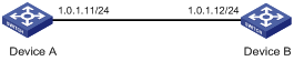
Perform the following configurations to synchronize the time between Device B and Device A:
· As shown in Figure 7, the local clock of Device A is to be used as a reference source, with the stratum level 2.
· Device B operates in client/server mode and Device A is to be used as the NTP server of Device B.
Configuration procedure
1. Set the IP address for each interface as shown in Figure 7. (Details not shown.)
2. Configure Device B:
# Display the NTP status of Device B before clock synchronization.
<DeviceB> display ntp-service status
Clock status: unsynchronized
Clock stratum: 16
Reference clock ID: none
Nominal frequency: 64.0000 Hz
Actual frequency: 64.0000 Hz
Clock precision: 2^7
Clock offset: 0.0000 ms
Root delay: 0.00 ms
Root dispersion: 0.00 ms
Peer dispersion: 0.00 ms
Reference time: 00:00:00.000 UTC Jan 1 1900 (00000000.00000000)
# Specify Device A as the NTP server of Device B so that Device B synchronizes to Device A.
<DeviceB> system-view
[DeviceB] ntp-service unicast-server 1.0.1.11
# Display the NTP status of Device B after clock synchronization.
[DeviceB] display ntp-service status
Clock status: synchronized
Clock stratum: 3
Reference clock ID: 1.0.1.11
Nominal frequency: 64.0000 Hz
Actual frequency: 64.0000 Hz
Clock precision: 2^7
Clock offset: 0.0000 ms
Root delay: 31.00 ms
Root dispersion: 1.05 ms
Peer dispersion: 7.81 ms
Reference time: 14:53:27.371 UTC Sep 19 2012 (C6D94F67.5EF9DB22)
The output shows that Device B has synchronized to Device A. The stratum level of Device B is 3, and that of Device A is 2.
# Display NTP session information for Device B, which shows that an association has been set up between Device B and Device A.
[DeviceB] display ntp-service sessions
source reference stra reach poll now offset delay disper
**************************************************************************
[12345] 1.0.1.11 127.127.1.0 2 63 64 3 -75.5 31.0 16.5
note: 1 source(master),2 source(peer),3 selected,4 candidate,5 configured
Total associations : 1
NTP symmetric peers mode configuration example
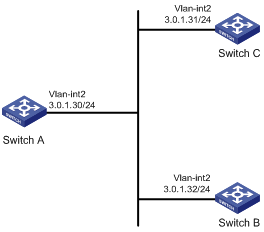
Network requirements
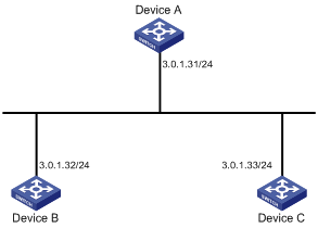
· As shown in Figure 8, configure Device A as a reference source, with the stratum level 2.
· Configure Device B to operate in client mode and use Device A as its NTP server.
· Configure Device C to operate in symmetric-active mode and use Device B as its symmetric-passive peer.
Configuration procedure
1. Configure IP addresses for interfaces. (Details not shown.)
2. Configure Device B:
# Specify Device A as the NTP server of Device B.
<DeviceB> system-view
[DeviceB] ntp-service unicast-server 3.0.1.31
3. Display the NTP status of Device B after clock synchronization.
[DeviceB] display ntp-service status
Clock status: synchronized
Clock stratum: 3
Reference clock ID: 3.0.1.31
Nominal frequency: 100.0000 Hz
Actual frequency: 100.0000 Hz
Clock precision: 2^18
Clock offset: -21.1982 ms
Root delay: 15.00 ms
Root dispersion: 775.15 ms
Peer dispersion: 34.29 ms
Reference time: 15:22:47.083 UTC Sep 19 2013 (C6D95647.153F7CED)
The output shows that Device B has synchronized to Device A because it has a higher stratum than Device A.
4. Configure Device C (after Device B is synchronized to Device A):
# Configure Device C as a symmetric peer after local synchronization.
[DeviceC] ntp-service unicast-peer 3.0.1.32
The output shows that Device B and Device C are configured as symmetric peers, with Device C in symmetric-active mode and Device B in symmetric-passive mode. Because the stratus level of Device C is 16 while that of Device B is 3, Device B synchronizes to Device C.
# Display the NTP status of Device C after clock synchronization.
[DeviceC] display ntp-service status
Clock status: synchronized
Clock stratum: 4
Reference clock ID: 3.0.1.32
Nominal frequency: 100.0000 Hz
Actual frequency: 100.0000 Hz
Clock precision: 2^18
Clock offset: -21.1982 ms
Root delay: 15.00 ms
Root dispersion: 775.15 ms
Peer dispersion: 34.29 ms
Reference time: 15:22:47.083 UTC Sep 19 2013 (C6D95647.153F7CED)
The output shows that Device C has synchronized to Device B because it has a higher stratum than Device B.
# Display NTP session information for Device C.
[DeviceC] display ntp-service sessions
source reference stra reach poll now offset delay disper
********************************************************************************
[12345] 3.0.1.32 3.0.1.31 3 3 64 16 -6.4 4.8 1.0
note: 1 source(master),2 source(peer),3 selected,4 candidate,5 configured
Total associations : 1
The output shows that an association has been set up between Device B and Device C.
NTP broadcast mode configuration example
Network requirements
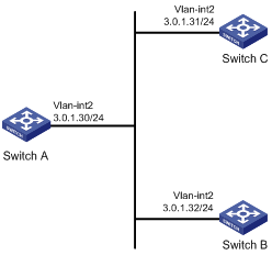
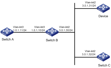
As shown in Figure 9, Switch C functions as the NTP server for multiple devices on a network segment and synchronizes the time among multiple devices.
· Switch C’s local clock is to be used as a reference source, with the stratum level 2.
· Switch C operates in broadcast server mode and sends out broadcast messages from VLAN-interface 2.
· Switch A and Switch B operate in broadcast client mode, and listen to broadcast messages through their VLAN-interface 2 respectively.
Configuration procedure
1. Set the IP address for each interface as shown in Figure 9. (Details not shown.)
2. Configure Switch C:
# Configure Switch C to operate in broadcast server mode and send broadcast messages through VLAN-interface 2.
[SwitchC] interface vlan-interface 2
[SwitchC-Vlan-interface2] ntp-service broadcast-server
3. Configure Switch A:
# Configure Switch A to operate in broadcast client mode and receive broadcast messages on VLAN-interface 2.
<SwitchA> system-view
[SwitchA] interface vlan-interface 2
[SwitchA-Vlan-interface2] ntp-service broadcast-client
4. Configure Switch B:
# Configure Switch B to operate in broadcast client mode and receive broadcast messages on VLAN-interface 2.
<SwitchB> system-view
[SwitchB] interface vlan-interface 2
[SwitchB-Vlan-interface2] ntp-service broadcast-client
Switch A and Switch B get synchronized upon receiving a broadcast message from Switch C.
# Take Switch A as an example. Display the NTP status of Switch A after clock synchronization.
[SwitchA-Vlan-interface2] display ntp-service status
Clock status: synchronized
Clock stratum: 3
Reference clock ID: 3.0.1.31
Nominal frequency: 64.0000 Hz
Actual frequency: 64.0000 Hz
Clock precision: 2^7
Clock offset: 0.0000 ms
Root delay: 31.00 ms
Root dispersion: 8.31 ms
Peer dispersion: 34.30 ms
Reference time: 16:01:51.713 UTC Sep 19 2012 (C6D95F6F.B6872B02)
The output shows that Switch A has synchronized to Switch C. The stratum level of Switch A is 3, and that of Switch C is 2.
# Display NTP session information for Switch A, which shows that an association has been set up between Switch A and Switch C.
[SwitchA-Vlan-interface2] display ntp-service sessions
source reference stra reach poll now offset delay disper
**************************************************************************
[1234] 3.0.1.31 127.127.1.0 2 254 64 62 -16.0 32.0 16.6
note: 1 source(master),2 source(peer),3 selected,4 candidate,5 configured
Total associations : 1
NTP multicast mode configuration example
Network requirements
As shown in Figure 10, the device functions as the NTP server for multiple devices on different network segments and synchronizes the time among multiple devices.
· The local clock of the device is to be used as a reference source, with the stratum level 2.
· The device operates in multicast server mode and sends out multicast messages from VLAN-interface 2.
· Switch A and Switch C operate in multicast client mode and receive multicast messages through VLAN-interface 3 and VLAN-interface 2, respectively.
Configuration procedure
1. Set the IP address for each interface as shown in Figure 10. (Details not shown.)
2. Configure the device:
# Configure the device to operate in multicast server mode and send multicast messages through VLAN-interface 2.
[Device] interface vlan-interface 2
[Device-Vlan-interface2] ntp-service multicast-server
3. Configure Switch C:
# Configure Switch C to operate in multicast client mode and receive multicast messages on VLAN-interface 2.
<SwitchC> system-view
[SwitchC] interface vlan-interface 2
[SwitchC-Vlan-interface2] ntp-service multicast-client
Because Switch C and the device are on the same subnet, Switch C can receive the multicast messages from the device without being enabled with the multicast functions and can synchronize to the device.
# Display the NTP status of Switch C after clock synchronization.
[SwitchC-Vlan-interface2] display ntp-service status
Clock status: synchronized
Clock stratum: 3
Reference clock ID: 3.0.1.31
Nominal frequency: 64.0000 Hz
Actual frequency: 64.0000 Hz
Clock precision: 2^7
Clock offset: 0.0000 ms
Root delay: 31.00 ms
Root dispersion: 8.31 ms
Peer dispersion: 34.30 ms
Reference time: 16:01:51.713 UTC Sep 19 2012 (C6D95F6F.B6872B02)
The output shows that Switch C has synchronized to the device. The stratum level of Switch C is 3, and that of the device is 2.
# Display NTP session information for Switch C, which shows that an association has been set up between Switch C and the device.
[SwitchC-Vlan-interface2] display ntp-service sessions
source reference stra reach poll now offset delay disper
**************************************************************************
[1234] 3.0.1.31 127.127.1.0 2 254 64 62 -16.0 31.0 16.6
note: 1 source(master),2 source(peer),3 selected,4 candidate,5 configured
Total associations : 1
4. Configure Switch B:
Because Switch A and the device are on different subnets, you must enable the multicast function on Switch B before Switch A can receive multicast messages from the device.
# Enable IP multicast routing and IGMP.
<SwitchB> system-view
[SwitchB] multicast routing-enable
[SwitchB] interface vlan-interface 2
[SwitchB-Vlan-interface2] pim dm
[SwitchB-Vlan-interface2] quit
[SwitchB] vlan 3
[SwitchB-vlan3] port gigabitethernet 1/0/1
[SwitchB-vlan3] quit
[SwitchB] interface vlan-interface 3
[SwitchB-Vlan-interface3] igmp enable
[SwitchB-Vlan-interface3] igmp static-group 224.0.1.1
[SwitchB-Vlan-interface3] quit
[SwitchB] interface gigabitethernet 1/0/1
[SwitchB-GigabitEthernet1/0/1] igmp-snooping static-group 224.0.1.1 vlan 3
5. Configure Switch A:
# Configure Switch A to operate in multicast client mode and receive multicast messages on VLAN-interface 3.
<SwitchA> system-view
[SwitchA] interface vlan-interface 3
[SwitchA-Vlan-interface3] ntp-service multicast-client
# Display the NTP status of Switch A after clock synchronization.
[SwitchA-Vlan-interface3] display ntp-service status
Clock status: synchronized
Clock stratum: 3
Reference clock ID: 3.0.1.31
Nominal frequency: 64.0000 Hz
Actual frequency: 64.0000 Hz
Clock precision: 2^7
Clock offset: 0.0000 ms
Root delay: 40.00 ms
Root dispersion: 10.83 ms
Peer dispersion: 34.30 ms
Reference time: 16:02:49.713 UTC Sep 19 2012 (C6D95F6F.B6872B02)
The output shows that Switch A has synchronized to the device. The stratum level of Switch A is 3, and that of the device is 2.
# Display NTP session information for Switch A, which shows that an association has been set up between Switch A and the device.
[SwitchA-Vlan-interface3] display ntp-service sessions
source reference stra reach poll now offset delay disper
**************************************************************************
[1234] 3.0.1.31 127.127.1.0 2 255 64 26 -16.0 40.0 16.6
note: 1 source(master),2 source(peer),3 selected,4 candidate,5 configured
Total associations : 1
Configuration example for NTP client/server mode with authentication
Network requirements
As shown in Figure 11, perform the following configurations to synchronize the time between Device B and Device A and ensure network security.
· The local clock of Device A is to be configured as a reference source, with the stratum level 2.
· Device B operates in client mode and Device A is to be used as the NTP server of Device B, with Device B as the client.
· NTP authentication is to be enabled on both Device A and Device B.
Configuration procedure
1. Set the IP address for each interface as shown in Figure 11. (Details not shown.)
2. Configure Device B:
<DeviceB> system-view
# Enable NTP authentication on Device B.
[DeviceB] ntp-service authentication enable
# Set an authentication key.
[DeviceB] ntp-service authentication-keyid 42 authentication-mode md5 aNiceKey
# Specify the key as a trusted key.
[DeviceB] ntp-service reliable authentication-keyid 42
# Specify Device A as the NTP server of Device B.
[DeviceB] ntp-service unicast-server 1.0.1.11 authentication-keyid 42
Before Device B can synchronize its clock to that of Device A, enable NTP authentication for Device A.
Perform the following configuration on Device A:
# Enable NTP authentication.
[DeviceA] ntp-service authentication enable
# Set an authentication key.
[DeviceA] ntp-service authentication-keyid 42 authentication-mode md5 aNiceKey
# Specify the key as a trusted key.
[DeviceA] ntp-service reliable authentication-keyid 42
# Display the NTP status of Device B after clock synchronization.
[DeviceB] display ntp-service status
Clock status: synchronized
Clock stratum: 3
Reference clock ID: 1.0.1.11
Nominal frequency: 64.0000 Hz
Actual frequency: 64.0000 Hz
Clock precision: 2^7
Clock offset: 0.0000 ms
Root delay: 31.00 ms
Root dispersion: 1.05 ms
Peer dispersion: 7.81 ms
Reference time: 14:53:27.371 UTC Sep 19 2012 (C6D94F67.5EF9DB22)
The output shows that Device B has synchronized to Device A. The stratum level of Device B is 3, and that of Device A is 2.
# Display NTP session information for Device B, which shows that an association has been set up between Device B and Device A.
[DeviceB] display ntp-service sessions
source reference stra reach poll now offset delay disper
**************************************************************************
[12345] 1.0.1.11 127.127.1.0 2 63 64 3 -75.5 31.0 16.5
note: 1 source(master),2 source(peer),3 selected,4 candidate,5 configured
Total associations : 1
Configuration example for NTP broadcast mode with authentication
Network requirements
As shown in Figure 12, Switch C functions as the NTP server for multiple devices on different network segments and synchronizes the time among multiple devices. Switch B authenticates the reference source.
· Switch C’s local clock is to be used as a reference source, with the stratum level 3.
· Switch C operates in broadcast server mode and sends out broadcast messages from VLAN-interface 2.
· Switch A and Switch B operate in broadcast client mode and receive broadcast messages through VLAN-interface 2.
· NTP authentication is enabled on both Switch B and Switch C.
Configuration procedure
1. Set the IP address for each interface as shown in Figure 12. (Details not shown.)
2. Configure Switch A:
# Configure Switch A to operate in NTP broadcast client mode and receive NTP broadcast messages on VLAN-interface 2.
<SwitchA> system-view
[SwitchA] interface vlan-interface 2
[SwitchA-Vlan-interface2] ntp-service broadcast-client
3. Configure Switch B:
# Enable NTP authentication on Switch B. Configure an NTP authentication key, with the key ID of 88 and key value of 123456. Specify the key as a trusted key.
<SwitchB> system-view
[SwitchB] ntp-service authentication enable
[SwitchB] ntp-service authentication-keyid 88 authentication-mode md5 123456
[SwitchB] ntp-service reliable authentication-keyid 88
# Configure Switch B to operate in broadcast client mode and receive NTP broadcast messages on VLAN-interface 2.
[SwitchB] interface vlan-interface 2
[SwitchB-Vlan-interface2] ntp-service broadcast-client
4. Configure Switch C:
# Configure Switch C to operate in NTP broadcast server mode and use VLAN-interface 2 to send NTP broadcast packets.
[SwitchC] interface vlan-interface 2
[SwitchC-Vlan-interface2] ntp-service broadcast-server
[SwitchC-Vlan-interface2] quit
# Switch A synchronizes its local clock based on the received broadcast messages sent from Switch C. Display NTP service status information on Switch A, and you can see that Switch A has synchronized to Switch C, the stratum level of Switch A is 4, and the stratum level of Switch C is 3.
[SwitchA-Vlan-interface2] display ntp-service status
Clock status: synchronized
Clock stratum: 4
Reference clock ID: 3.0.1.31
Nominal frequency: 64.0000 Hz
Actual frequency: 64.0000 Hz
Clock precision: 2^7
Clock offset: 0.0000 ms
Root delay: 31.00 ms
Root dispersion: 8.31 ms
Peer dispersion: 34.30 ms
Reference time: 16:01:51.713 UTC Sep 19 2012 (C6D95F6F.B6872B02)
# Display NTP session information for Switch A, which shows that an association has been set up between Switch A and Switch C.
[SwitchA-Vlan-interface2] display ntp-service sessions
source reference stra reach poll now offset delay disper
**************************************************************************
[1234] 3.0.1.31 127.127.1.0 3 254 64 62 -16.0 32.0 16.6
note: 1 source(master),2 source(peer),3 selected,4 candidate,5 configured
Total associations : 1
# NTP authentication is enabled on Switch B, but not enabled on Switch C, so Switch B cannot synchronize to Switch C.
[SwitchB-Vlan-interface2] display ntp-service status
Clock status: unsynchronized
Clock stratum: 16
Reference clock ID: none
Nominal frequency: 100.0000 Hz
Actual frequency: 100.0000 Hz
Clock precision: 2^18
Clock offset: 0.0000 ms
Root delay: 0.00 ms
Root dispersion: 0.00 ms
Peer dispersion: 0.00 ms
Reference time: 00:00:00.000 UTC Jan 1 1900(00000000.00000000)
# Enable NTP authentication on Switch C. Configure an NTP authentication key, with the key ID of 88 and key value of 123456. Specify the key as a trusted key.
[SwitchC] ntp-service authentication enable
[SwitchC] ntp-service authentication-keyid 88 authentication-mode md5 123456
[SwitchC] ntp-service reliable authentication-keyid 88
# Specify Switch C as an NTP broadcast server, and associate the key 88 with Switch C.
[SwitchC] interface vlan-interface 2
[SwitchC-Vlan-interface2] ntp-service broadcast-server authentication-keyid 88
# After NTP authentication is enabled on Switch C, Switch B can synchronize to Switch C. Display NTP service status information on Switch B, and you can see that Switch B has synchronized to Switch C, the stratum level of Switch B is 4, and the stratum level of Switch C is 3.
[SwitchB-Vlan-interface2] display ntp-service status
Clock status: synchronized
Clock stratum: 4
Reference clock ID: 3.0.1.31
Nominal frequency: 64.0000 Hz
Actual frequency: 64.0000 Hz
Clock precision: 2^7
Clock offset: 0.0000 ms
Root delay: 31.00 ms
Root dispersion: 8.31 ms
Peer dispersion: 34.30 ms
Reference time: 16:01:51.713 UTC Sep 19 2012 (C6D95F6F.B6872B02)
# Display NTP session information for Switch B, which shows that an association has been set up between Switch B and Switch C.
[SwitchB-Vlan-interface2] display ntp-service sessions
source reference stra reach poll now offset delay disper
**************************************************************************
[1234] 3.0.1.31 127.127.1.0 3 254 64 62 -16.0 32.0 16.6
note: 1 source(master),2 source(peer),3 selected,4 candidate,5 configured
Total associations : 1
# Configuration of NTP authentication on Switch C does not affect Switch A. Switch A still synchronizes to Switch C.
[SwitchA-Vlan-interface2] display ntp-service status
Clock status: synchronized
Clock stratum: 4
Reference clock ID: 3.0.1.31
Nominal frequency: 64.0000 Hz
Actual frequency: 64.0000 Hz
Clock precision: 2^7
Clock offset: 0.0000 ms
Root delay: 31.00 ms
Root dispersion: 8.31 ms
Peer dispersion: 34.30 ms
Reference time: 16:01:51.713 UTC Sep 19 2012 (C6D95F6F.B6872B02)