- Table of Contents
- Related Documents
-
| Title | Size | Download |
|---|---|---|
| 02-Installing the device | 664.53 KB |
Contents
Confirming installation preparations
Mounting the device on a workbench
Attaching the ring terminal to the grounding cable
Connecting the grounding cable to the device
Connecting the console cable and setting terminal parameters
Connecting the Ethernet cables
Connecting a copper Ethernet port
Installing the device
|
|
WARNING! Keep the tamper-proof seal on a mounting screw on the chassis cover intact, and if you want to open the chassis, contact H3C Support for permission. Otherwise, H3C shall not be liable for any consequence. |
Confirming installation preparations
Before you install the device, verify that you have read "Preparing for installation" carefully and the installation site meets all the requirements.
Installation flow
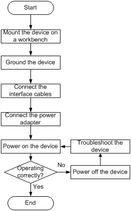
Mounting the device on a workbench
|
|
IMPORTANT: Do not place heavy objects on the device. |
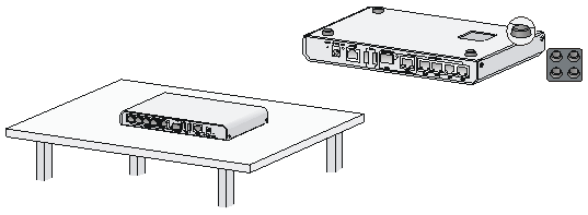
To mount the device on a workbench:
1. Place the device with bottom up and clean the round holes in the chassis bottom.
2. Attach the rubber feet to the four round holes in the chassis bottom.
3. Place the switch with upside up on the workbench.
Figure 2 Mounting the device on a workbench
Grounding the device
|
|
WARNING! · Correctly connecting the device grounding cable is crucial to lightning protection and EMI protection. · Connect the grounding cable to the grounding system in the equipment room. Do not connect it to a fire main or lightning rod. |
No grounding cable is provided with the device. Prepare a grounding cable yourself.
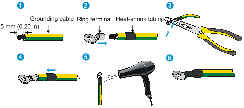
Attaching the ring terminal to the grounding cable
1. Cut the grounding cable as appropriate for connecting to the grounding strip.
2. Use a wire stripper to strip 5 mm (0.20 in) of insulation off the end of the grounding cable.
3. Slide the heat-shrink tubing onto the cable and insert the bare metal part into the end of the ring terminal.
4. Use a crimper to secure the metal part of the cable to the ring terminal.
5. Slide the heat-shrink tubing down the cable until the tubing covers the joint.
6. Use a blow dryer to shrink the tubing around the cable.
Figure 3 Attaching the ring terminal to the grounding cable
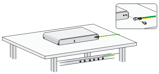
Connecting the grounding cable to the device
1. Use a Phillips screwdriver to remove the grounding screw from the rear panel of chassis.
2. Use the grounding screw to attach the ring terminal of the grounding cable to the chassis.
3. Connect the other end of the grounding cable to the grounding strip.
Make sure the grounding strip has been reliably grounded.
Figure 4 Grounding the device with a grounding strip
Connecting the console cable and setting terminal parameters
Connecting the console cable
1. Prepare a configuration terminal.
The configuration terminal can be an ASCII terminal with an RS232 serial port or a PC. The description in this section assumes that you use a PC as the configuration terminal.
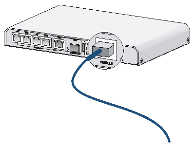
2. Connect the console cable:
a. Plug the DB-9 female connector of the console cable to the serial port of the PC.
b. Connect the RJ-45 connector to the console port of the device.
Figure 5 Connecting the console cable
|
|
NOTE: · Identify the mark on the console port and make sure you are connecting to the correct port. · The serial ports on PCs do not support hot swapping. To connect a PC to an operating device, first connect the PC end. To disconnect a PC from an operating device, first disconnect the device end. |
Setting terminal parameters
To set terminal parameters, for example, on a Windows 95/98/NT/2000/XP HyperTerminal:
1. Select Start > All Programs > Accessories > Communications > HyperTerminal.
The Connection Description dialog box appears.
2. Enter a name for the new connection in the Name field and click OK.
Figure 6 Connection description

3. Select the serial port to be used from the Connect using list, and click OK.
Figure 7 Setting the serial port used by the HyperTerminal connection

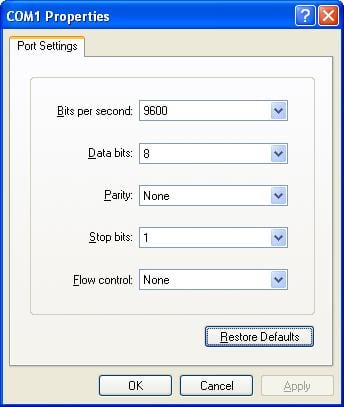
4. Set Bits per second to 9600, Data bits to 8, Parity to None, Stop bits to 1, and Flow control to None, and click OK.
To restore the default settings, click Restore Defaults.
Figure 8 Setting the serial port parameters
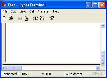
5. Select File > Properties in the HyperTerminal window.
Figure 9 HyperTerminal window
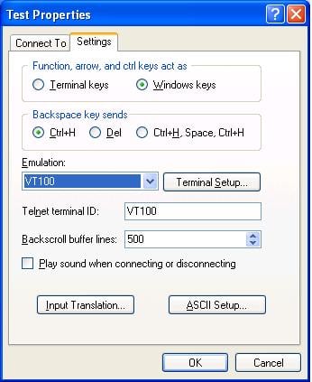
6. On the Settings tab, set the emulation to VT100 or Auto detect and click OK.
Figure 10 Setting the terminal emulation in Test Properties dialog box
Connecting the Ethernet cables
Connecting a copper Ethernet port
1. Connect one end of the Ethernet cable to the copper Ethernet port on the device, and the other end to the Ethernet port on the peer device.
2. After powering on the device, examine the LEDs of the fixed copper Ethernet port.
For more information about the LED description, see "Appendix B LEDs."
Connecting a fiber port
No transceiver module is provided with the device. The device supports only LC-type fiber connectors. For transceiver module specifications, see "Appendix A Chassis views and technical specifications."
Follow these guidelines when you connect an optical fiber:
· Never stare into an open fiber port, because invisible rays might be emitted from the fiber port.
· Install dust plugs in empty fiber ports.
· Never bend a fiber excessively. The bend radius should not be less than 10 cm (3.94 in).
· Make sure the Tx and Rx ports on a transceiver module are correctly connected.
To connect the device to the network through an optical fiber:
1. Remove the dust plug from the fiber port.
2. Remove the dust cover from the transceiver module, and insert the transceiver module into the fiber port.
3. Remove the dust covers from the optical fiber connector.
4. Identify the Rx and Tx ports on the transceiver module. Use the optical fiber to connect the Rx port and Tx port on the transceiver module to the Tx port and Rx port on the peer end, respectively.
5. Power on the device, and examine the fiber port LED:
¡ If the LED is on, a fiber link is present.
¡ If the LED is off, no link is present. Verify that the Tx and Rx ports are correctly connected.
Figure 11 Connecting an optical fiber

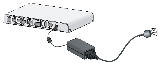
Connecting the power adapter
1. Make sure the device is reliably grounded.
2. Connect the power adapter to an AC power source.
3. Connect the DC power connector on the power adapter to the power adapter receptacle on the front panel of the device.
Figure 12 Connecting the power adapter
Verifying the installation
Before powering on the device, verify that:
· The workbench is stable.
· There is sufficient clearance around the device.
· The power source is as required.
· The grounding cable is securely connected.
· The console cable and power cord are correctly connected.
Powering on the device
1. Power on the device. The device initializes its memory and runs BootWare. The following information appears on the terminal screen:
System is starting...
Press Ctrl+D to access BASIC-BOOTWARE MENU
Press Ctrl+T to start heavy memory test
Booting Normal Extend BootWare
The Extend BootWare is self-decompressing...................................
..Done!
****************************************************************************
* *
* H3C WX2540E BootWare, Version 1.02 *
* *
****************************************************************************
Copyright (c) 2004-2017 New H3C Technologies Co., Ltd.
Compiled Date : May 19 2016
CPU Type : BCM58622
CPU L1 Cache : 32KB
CPU Clock Speed : 1200MHz
Memory Type : DDR3 SDRAM
Memory Size : 1024MB
Memory Speed : 800MHz
BootWare Size : 896KB
Flash Size : 1024MB
CPLD Version : 002
PCB Version : Ver.B
BootWare Validating...
Press Ctrl+B to enter extended boot menu...
2. Press Ctrl + B at the prompt within 4 seconds to access the Boot menu. Otherwise, the system enters the system image file reading and self-compressing process.
To access the Boot menu after the system enters the system image file reading and self-compressing process, restart the device.
Starting to get the main application file-- flash:/wx2500.bin!...
............................................................
The main application file is self-decompressing.............................
............................................................................
......................................................Done!
System application is starting...
User interface con0 is available.
Press ENTER to get started.
Press Enter at the prompt, and you can configure the device when the prompt <H3C> appears.
During the startup process, the CPLD is automatically upgraded to the latest version.
