- Table of Contents
- Related Documents
-
| Title | Size | Download |
|---|---|---|
| 01-Text | 2.46 MB |
Contents
Examining the installation site
Installation tools and equipment
Installing the mounting brackets and chassis rails
Installing an LPU with standard ejector levers
Installing an LPU with foldable ejector levers
Installing and removing fan trays
Installing and removing power modules
(Optional) Installing a DC input terminal block
(Optional) Installing transceiver modules
Installing an SFP+/SFP/QSFP+/QSFP28 module
Connecting an SFP+/QSFP+/QSFP28/QSFP+ to SFP+ cable
Preparing for installation
ESD prevention
To prevent electronic components from electrostatic discharge (ESD) damage, wear an ESD wrist strap and make sure it makes good skin contact and is reliably grounded before you touch any switch module.
Examining the installation site
The switch must be used indoors. To make sure the switch operates correctly and to prolong its service lifetime, the installation site must meet the load-bearing, temperature, humidity, cleanliness, EMI, grounding, power supply, ventilation, and space requirements. Reserve a minimum of 1.2 m (3.94 ft) of clearance between the switch and walls or other devices. For more information, see H3C S12500X-AF Switch Series Installation Guide.
Installation tools and equipment
No installation tools and equipment are provided with the switch. Prepare the following tools yourself:
· Phillips screwdriver.
· ESD wrist strap.
· Marker.
Installing the switch
Switch dimensions
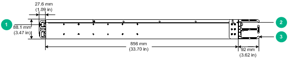
Figure 1 Switch dimensions
|
(1) Power module latch |
(2) Mounting bracket |
|
(3) Cable management bracket |
|
Rack requirements
|
Model |
Switch dimensions |
Rack requirements |
|
S12501X-AF |
· Height—88.1 mm (3.47 in) (2 RU). · Width—440 mm (17.32 in). · Total depth—975.6 mm (38.41 in) ? 856 mm (33.70 in) for the chassis. ? 92 mm (3.62 in) from the rear side of the mounting bracket rear ear to the management bracket front end. ? 27.6 mm (1.09 in) for the power module latch at the chassis rear. |
· A minimum of 1.1 m (3.61 ft) in depth (recommended.) · A minimum of 130 mm (5.12 in) from the front rack post to the front door. · A minimum of 950 mm (37.40 in) from the front rack post to the rear door. |
|
|
NOTE: As a best practice, use a rack that has a single door at the front. |
Installing the mounting brackets and chassis rails
Attach the mounting brackets to the chassis front and the chassis rails to installation position a, b, c, d, or e as shown in Figure 2. The installation position depends on the distance between the front and the rear rack posts. The cable management brackets have been attached on the mounting brackets and do not require separate installation.
To install the mounting brackets and chassis rails:
1. Read the sign on each mounting bracket to identify the left and right mounting brackets. The left mounting bracket is marked L and the right mounting bracket is marked R.
2. Align the round holes in the wide flange of one mounting bracket with the screw holes in the chassis. See Figure 2.
3. Use M4 screws provided with the switch to attach the mounting bracket to the chassis.
4. Determine the installation position of the chassis rails based on the distance between the front and the rear rack posts. See Table 2.
5. Align the round holes in one chassis rail with the screw holes in the chassis. See Figure 2.
6. Use M4 screws provided with the switch to attach the chassis rail to the chassis.
7. Repeat the proceeding steps to install the other mounting bracket and chassis rail.
Figure 2 Installing the mounting bracket and chassis rail
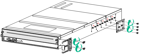
Table 2 Distance between the front and rear rack posts and installation position
|
Distance between the front and rear rack posts |
Installation position |
|
552 to 799 mm (21.73 to 31.46 in) |
Positon a |
|
617 to 864 mm (24.29 to 34.02 in) |
Positon b |
|
682 to 929 mm (26.85 to 36.57 in) |
Positon c |
|
747 to 994 mm (29.41 to 39.13 in) |
Positon d |
|
812 to 1059 mm (31.97 to 41.69 in) |
Positon e |
Installing slide rails
Install the slide rails on the rear posts.
To install slide rails:
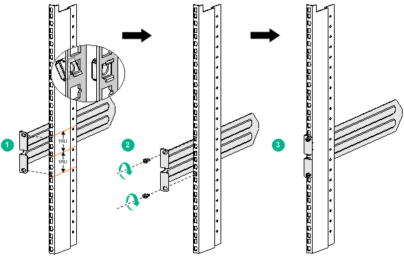
1. As shown in Figure 3, mark the installation positions on a rack post for installing the slide rail. The slide rail is 2 U high.
2. Install a cage nut in each marked position, as shown by callout 1 in Figure 3.
3. Align the installation holes on the slide rail with the cage nuts on the rack post, and use screws to attach the slide rail to the rack post. See callout 2 in Figure 3.
4. Repeat the proceeding steps to install the other slide rail.
Make sure the two slide rails are at the same height.
Figure 3 Installing the slide rail (rear view)
Mounting the switch in a rack
|
|
WARNING! · Two persons are required to mount the switch in a rack. · Support the switch bottom from both sides to move the switch. Do not hold the handle of a fan tray, power module, or card to move the switch. Any attempt to carry the switch with these parts might cause equipment damage or even bodily injury. · After you place the switch on the slide rails, do not leave go of your hands immediately because this might tip the switch, damaging the switch or even causing bodily injury. |
|
|
CAUTION: · Do not place your hand into any slot when you move the chassis. · Mount the switch in a rack from the front to prevent the mounting brackets and cable management brackets from getting jammed in the rack. |
To mount the switch in the rack:
1. Make sure the mounting brackets and chassis rails have been attached to the chassis. For the installation procedure, see "Installing the mounting brackets and chassis rails."
2. Make sure the slide rails have been attached to the rear posts. For the installation procedure, see "Installing slide rails."
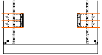
3. Determine the installation holes on the front posts for the mounting brackets. Install four cage nuts on the left front post and two cage nuts on the right front post.
The mounting bracket is 2 RU high. On the left front post, the uppermost, the lowermost, and the two middle installation holes require cage nuts. On the right front post, only the uppermost and lowermost installation holes require cage nuts. See Figure 4.
Make sure the uppermost cage nuts on the four rack posts are at the same height.
Figure 4 Installing cage nuts on the front rack posts
4. Supporting the switch bottom, one person aligns the chassis rails with the slide rails and slides the switch into the rack along the chassis rails until the switch stops.
Make sure the slide rails fit into the chassis rails correctly and the front ends of the slide rails extend out of the chassis rails. See Figure 5.
5. The other person uses screws provided with the switch to secure the switch in the rack.
If the mounting holes in the mounting brackets cannot align with the cage nuts on the rack, verify that the cage nuts are installed in the correct holes.
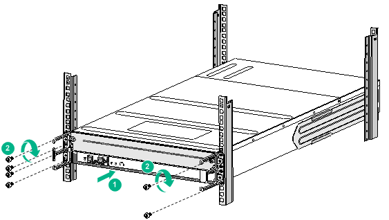
Figure 5 Mounting the switch in the rack
|
(1) Slide the chassis into the rack |
(2) Use screws to secure the mounting brackets to the rack |
Grounding the switch
|
|
CAUTION: · Grounding the switch reliably is crucial to lightning protection and EMI protection. Ground the switch reliably before you use it. · Use the grounding cable (yellow-green grounding cable) provided with the switch. · Connect the grounding cable to the earthing system in the equipment room. Do not connect it to a fire main or lightning rod. |
To connect the grounding cable to the grounding strip:
1. Unpack the grounding cable.
The grounding cable provided with the switch is compliant with the NEBS standards. The two-hole grounding lug of the grounding cable is used for connecting the chassis. The ring terminal of the grounding cable is used for connecting the grounding strip.
2. Remove the grounding screws from the grounding holes at the rear of the chassis.
A grounding sign is provided with the grounding holes, as shown by callout 1 in Figure 6.
3. Use grounding screws to attach the two-hole grounding lug of the grounding cable to the chassis.
|
|
IMPORTANT: For an S12501X-AF switch, attach the two-hole grounding lug to the chassis as shown in Figure 6 so that the grounding cable is on top of the grounding lug. |
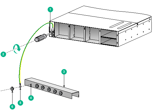
Figure 6 Connecting the grounding cable to a grounding strip
|
(1) Grounding sign |
(2) Use grounding screws to attach the two-hole grounding lug to the grounding point |
||
|
(3) Grounding strip |
(4) Grounding post |
(5) Ring terminal |
(6) Hex nut |
Installing FRUs
This section describes the installation procedures for the LPUs, fan trays, and power modules. For the compatibility matrix between these modules and the switch models, see H3C S12500X-AF Switch Series Installation Guide.
|
|
WARNING! Long-time exposure to strong air flow might cause discomfort. As a best practice, do not stand close to the air outlet vents while the switch is operating. If you must be next to the switch on the air outlet vent side for an extended period, avoid the air flow or take other protective measures. |
|
|
CAUTION: For good ventilation of the switch, install filler panels in empty card and power module slots. |
Attaching an ESD wrist strap
To prevent electronic components from ESD damage, wear an ESD wrist strap and make sure it makes good skin contact and is reliably grounded before you install FRUs.
Installing an LPU
|
|
CAUTION: The switch comes with the LPU slot installed with a filler panel. If you are not to install an LPU in the slot, keep the filler panel in slot. |
The S12500X-AF H LPUs are available for the switch.
Removing the filler panel
1. Loose the captive screws that secure the filler panel to the slot. See callout 1 in Figure 7.
2. As shown by callout 2 in Figure 7, remove the filler panel.
Keep the removed filler panel secure for future use.
Figure 7 Removing the filler panel
Installing an LPU with standard ejector levers
1. Orient the LPU with the upside up based on the orientation of the lettering on the LPU.
2. As shown by callout 1 in Figure 8, holding the LPU by the front panel with one hand and supporting its bottom with the other, gently slide the LPU into the slot along the slide rails.
Keep the LPU parallel to the slot to avoid damaging other components in the chassis.
3. As shown by callout 2 in Figure 8, rotate the ejector levers outward to the outmost when most of the LPU is inserted into the slot.
4. As shown by callout 3 in Figure 8, continue to push the LPU by its middle part on the front panel until you cannot move it.
5. As shown by callout 4 in Figure 8, push the ejector levers inward until they come in close contact with the panel.
6. As shown by callout 5 in Figure 8, fasten the captive screws to secure the LPU to the slot.
Figure 8 Installing an LPU with standard ejector levers
|
(1) Push the LPU slowly along the slide rails into the slot |
(2) Rotate the ejector levers outward |
|
(3) Push the LPU by the middle part on the front panel |
(4) Push the ejector levers inward |
|
(5) Fasten the captive screws on the LPU |
|
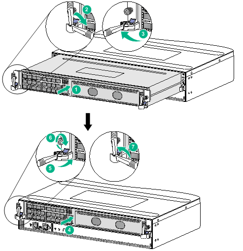
Installing an LPU with foldable ejector levers
1. Orient the LPU with the upside up based on the orientation of the lettering on the LPU.
2. As shown by callout 1 in Figure 9, holding the LPU by the front panel with one hand and supporting its bottom with the other, gently slide the LPU into the slot along the slide rails.
Keep the LPU parallel to the slot to avoid damaging other components in the chassis.
3. As shown by callout 2 in Figure 9, rotate the ejector levers downward to the horizontal position when most of the LPU is inserted into the slot.
4. As shown by callout 3 in Figure 9, rotate the ejector levers outward to the outmost.
5. As shown by callout 4 in Figure 9, continue to push the LPU by its middle part on the front panel until you cannot move it.
6. As shown by callout 5 in Figure 9, push the ejector levers inward until they come in close contact with the panel.
7. As shown by callout 6 in Figure 9, fasten the captive screws to secure the LPU to the chassis.
8. As shown by callout 7 in Figure 9, rotate the ejector levers upward to the vertical position.
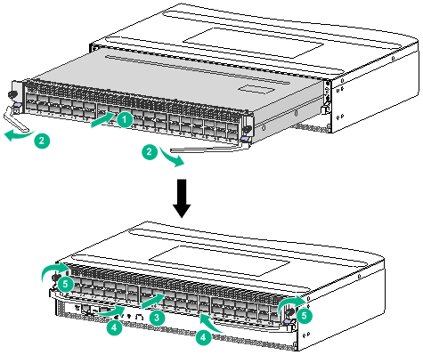
Figure 9 Installing an LPU with foldable ejector levers
|
(1) Push the LPU slowly along the slide rails into the slot |
|
(2) Rotate the ejector levers downward to the horizontal position |
|
(3) Rotate the ejector levers outward to the outmost |
|
(4) Push the LPU by the middle part on the front panel |
|
(5) Push the ejector levers inward until they come in close contact with the panel |
|
(6) Fasten the captive screws on the LPU |
|
(7) Rotate the ejector levers upward to the vertical position |
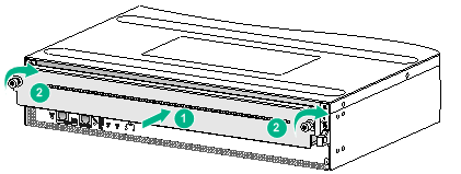
Installing the filler panel
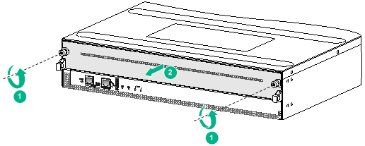
1. As shown by callout 1 in Figure 10, squeezing the captive screws on the filler panel, insert the filler panel into the slot.
2. As shown by callout 2 in Figure 10, fasten the captive screws on the filler panel.
Figure 10 Installing the filler panel
Installing and removing fan trays
Follow these restrictions and guidelines when you install a fan tray:
· For correct operation of the switch, install fan trays in all the three fan tray slots on the switch.
· The fan trays are hot swappable. Follow these guidelines when you hot swap a fan tray:
? Do not touch rotating fan blades.
? Ensure electricity safety.
? Replace a fan tray only when the other two fan trays are operating correctly.
· To avoid fan tray damage, use both hands when you install and remove a fan tray.
· When you hot swap a fan tray, the other operating fan trays automatically increase the fan rotation speed and make louder noise. Take protection measures such as wearing an earmuff or earplug. In addition, make good preparation before the hot swapping to minimize the operation time.
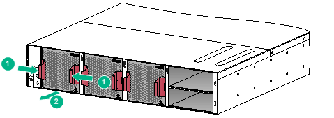
Installing fan trays
To install a fan tray in slot FAN3 for the switch:
1. Unpack the fan tray.
2. As shown by callouts 1 and 2 in Figure 11, orient the fan tray with the Top mark on the top. Grasping the fan tray handles with one hand and supporting the bottom of the fan tray with the other, slide the fan tray into the slot until the fan tray is fully seated in the slot and has a firm contact with the backplane.
Figure 11 Installing a fan tray
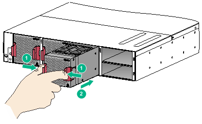
Removing a fan tray
1. As shown by callout 2 in Figure 12, grasp the fan tray handles and pull the fan tray out of the slot.
Support the fan tray bottom with one hand as you pull the fan tray out of the slot.
2. Place the removed fan tray on an antistatic mat or in an antistatic bag.
Installing and removing power modules
The installation and removal procedures are the same for DC and AC power modules. This section uses an AC power module as an example.
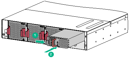
Installing a power module
To install a power module:
1. Unpack the power module. Make sure the power module model is as required.
2. Orient the power module with the upside down based on the orientation of the lettering on the power module.
3. Holding the power module with one hand on its handle, pulling the latch toward the handle with your thumb, and supporting the bottom of the power module with the other, slide the power module along the slide rails into the slot and release the latch. The latch automatically locks the power module in place.
Figure 13 Installing a power module
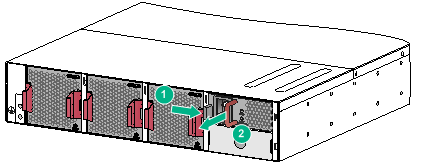
Removing a power module
|
|
CAUTION: Disconnect the power cable from the module before you remove a power module. |
To remove a power module:
1. Hold the handle on the power module with one hand and pull the latch toward the handle with your thumb. See callout 1 in Figure 14.
2. Pull the power module part out of the slot. Holding the bottom of the power module with the other hand, pull the power module out of the slot slowly. See callout 2 in Figure 14.
Figure 14 Removing a power module
Connecting the power cord
|
|
WARNING! · Power on the switch after you complete installation. · Turn off the circuit breaker before you connect the power cord. |
|
|
CAUTION: Make sure each power cord has a separate circuit breaker. |
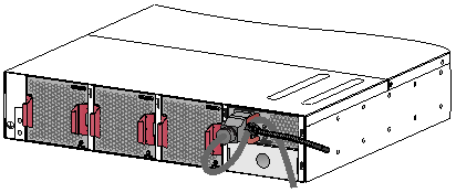
Connecting the AC power cord
1. Plug the AC power cord connector into the AC input receptacle of the power module.
2. Use a removable cable tie or self-adhesive cable tie (provided with the power module) to secure the power cord to the handle of the power module.
3. Connect the other end of the power cord to the AC power source.
Figure 15 Using a removable cable tie to secure the power cord to the switch
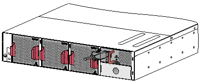
Connecting the DC power cord
To connect the DC power cord:
1. Connect the DC power cord connector to the DC input receptacle on the power module.
2. Fasten the screw on the connector to secure the connector to the receptacle.
3. Connect the other ends of the DC power cords to terminals of the power source.
Figure 16 Connecting the DC power cord
(Optional) Installing a DC input terminal block
A DC input terminal block provides eight pairs of terminals. Each pair provides one power line reconnection. A maximum of eight pairs of wires are supported. The terminals support a power cord with a size of 10 mm2 to 35 mm2 (0.02 sq.in to 0.05 sq.in).
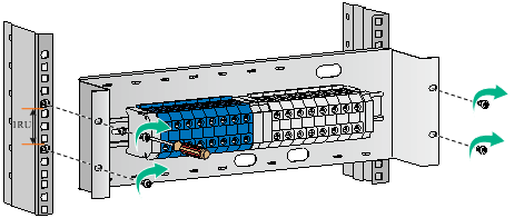
To attach a DC input terminal block to a rack:
1. Install cage nuts on the rack posts. For information about installing cage nuts, see "Installing the switch."
2. Use screws to attach the DC input terminal block to the rack, as shown in Figure 17.
Figure 17 Attaching a DC input terminal block to a rack
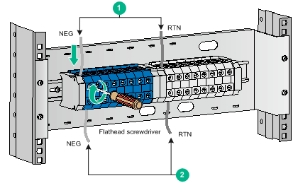
To connect cables to a DC input terminal block:
1. As shown by callout 1 in Figure 18, insert the blue and black wires of the extension cable into the DC input terminal block, and insert the other ends of the wires into the terminals on the power distribution box.
2. As shown by callout 2 in Figure 18, insert the blue and black wires of a DC power cord into the DC input terminal block, and insert the other ends of the wires into the DC input receptacle on the device.
Figure 18 Connecting cables to a DC input terminal block
(Optional) Installing transceiver modules
|
|
CAUTION: · To prevent particles from entering the ports, keep the dust plugs in the SFP+/SFP ports if you are not to install transceiver modules or cables in the ports. · To prevent particles from entering the ports, install the dust plugs that come with the LPUs in the QSFP+/QSFP28 ports if you are not to install transceiver modules or cables in the ports. |
Installing an SFP+/SFP/QSFP+/QSFP28 module
|
|
CAUTION: · Read the following instructions before you install an SFP+/SFP/QSFP+/QSFP28 module. Failure to follow these instructions might cause damage to the module. · Do not remove the dust plug from an SFP+/SFP/QSFP+/QSFP28 module if you are not to connect an optical fiber to the module. · Before you install an SFP+/SFP/QSFP+/QSFP28 module, remove the optical fiber (if any) from it. |
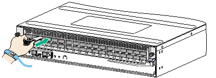
To install an SFP+/SFP/QSFP+/QSFP28 module:
1. Unpack the module.
Do not touch the golden plating of the module.
2. Pivot the clasp of the module up. Holding the module, gently push the module into the slot until it has firm contact with the slot, as shown in Figure 19.
? For a module that uses a plastic pull latch, skip this step.
? For an SFP+ module, press the module down so you can push the module straight into the port.
? If you cannot hold the module by its two sides because of high module density, press the module on its head end to push it in.
Figure 19 Installing an SFP+/SFP/QSFP+/QSFP28 module
Connecting an SFP+/QSFP+/QSFP28/QSFP+ to SFP+ cable
|
|
CAUTION: When you connect a fiber cable, make sure the bend radius of the cable is not less than eight times the fiber diameter. |
The cables are hot swappable.
Use SFP+ cables to connect SFP+ ports, QSFP+ cables to connect QSFP+ ports, QSFP28 cables to connect QSFP28 ports, and QSFP+ to SFP+ cables to connect QSFP+ and SFP+ ports.
To connect an SFP+/QSFP+/QSFP28/QSFP+ to SFP+ cable:
1. Unpack the cable.
2. Plug the cable connector into the port. Make sure the cable connector is correctly oriented.
Accessing the switch
The first time you access the switch you must use a console cable to connect a console terminal, for example, a PC, to the console port on the switch.
Connecting the console cable
|
|
IMPORTANT: · Identify the mark on the console port and make sure you are connecting to the correct port. · The serial ports on PCs do not support hot swapping. If the switch has been powered on, connect the console cable to the PC before connecting to the switch, and when you disconnect the cable, first disconnect from the switch. |
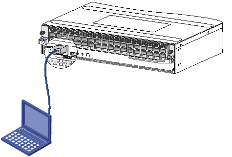
To connect the console cable:
1. Plug the DB-9 female connector of the console cable to the serial port of the PC.
2. Plug the RJ-45 connector of the console cable to the console port of the switch.
Figure 20 Connecting a terminal to the console port
Verification before login
Before you log in to the switch, perform the following tasks:
· Verify that the switch has been correctly installed.
· Verify that the card has been correctly installed.
· Verify that all the network cables, fibers, power cables, and grounding cables have been correctly connected.
· Verify that the voltage of the power source is as required.
· Verify that the console cable has been correctly connected, the terminal or PC used for configuration has started, and the configuration parameters have been set.
· Verify that the switch has been powered on.
