- Table of Contents
-
- 05-Layer 3 - IP Routing Configuration Examples
- 01-H3C_BGP_Configuration_Examples
- 02-H3C_BGP_Route_Selection_Configuration_Examples
- 03-H3C_IPv6_IS-IS_Configuration_Examples
- 04-H3C_IS-IS_Configuration_Examples
- 05-H3C_IS-IS_Route_Summarization_Configuration_Examples
- 06-H3C_OSPFv3_Configuration_Examples
- 07-H3C_OSPF_Configuration_Examples
- 08-H3C_Policy-Based_Routing_Configuration_Examples
- 09-H3C_Routing_Policy_Configuration_Examples
- Related Documents
-
| Title | Size | Download |
|---|---|---|
| 04-H3C_IS-IS_Configuration_Examples | 94.39 KB |
H3C IS-IS Configuration Examples
|
Copyright © 2017 New H3C Technologies Co., Ltd. All rights reserved. No part of this manual may be reproduced or transmitted in any form or by any means without prior written consent of New H3C Technologies Co., Ltd. The information in this document is subject to change without notice. |
|
Contents
Introduction
This document provides IS-IS configuration examples.
Prerequisites
The configuration examples in this document were created and verified in a lab environment, and all the devices were started with the factory default configuration. When you are working on a live network, make sure you understand the potential impact of every command on your network.
This document assumes that you have basic knowledge of IS-IS.
Example: Configuring IS-IS
Network configuration
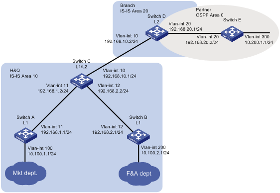
As shown in Figure 1, the company's headquarters and the branch run IS-IS. The partner runs OSPF.
Configure the switches to meet the following requirements:
· Reduce traffic for Switch A and Switch B because they have relative low performance.
· The Marketing department can reach the Finance department, the branch, and the partner.
· The Finance department and the branch cannot reach each other, and the branch does not have a route to the Finance department.
· When the IS-IS process on Switch C restarts, the communication is not interrupted.
Analysis
To meet the network requirements, you must perform the following tasks:
· To reduce traffic for Switch A and Switch B, configure them as Level-1 routers to allow communication only between the Marketing department and the Finance department.
· Configure route redistribution between IS-IS and OSPF on Switch D to allow communication between the Marketing department and the partner.
· Configure Switch C to use a prefix list to advertise only network 10.100.1.0/24 to Level-2 to ensure that the branch does not have a route to the Finance department.
· Enable IS-IS Graceful Restart (GR) on Switch C to ensure that the communication is not interrupted when the IS-IS process on Switch C restarts.
Software versions used
This configuration example was created and verified on S7500X-CMW710-R7536P05.
Restrictions and guidelines
To avoid blackhole routes, do not change the network topology during the IS-IS GR process.
Procedures
Configuring Switch A
# Configure an IP address for VLAN-interface 11.
<SwitchA> system-view
[SwitchA] interface vlan-interface 11
[SwitchA-Vlan-interface11] ip address 192.168.1.1 24
[SwitchA-Vlan-interface11] quit
# Configure IP addresses for other interfaces, as shown in Figure 1. (Details not shown.)
# Configure IS-IS.
[SwitchA] isis 1
[SwitchA-isis-1] is-level level-1
[SwitchA-isis-1] network-entity 10.1921.6800.1001.00
[SwitchA-isis-1] quit
[SwitchA] interface vlan-interface 11
[SwitchA–Vlan-interface11] isis enable 1
[SwitchA–Vlan-interface11] quit
[SwitchA] interface vlan-interface 100
[SwitchA–Vlan-interface100] isis enable 1
[SwitchA–Vlan-interface100] quit
Configuring Switch B
# Configure an IP address for VLAN-interface 12.
<SwitchB> system-view
[SwitchB] interface vlan-interface 12
[SwitchB-Vlan-interface12] ip address 192.168.2.1 24
[SwitchB-Vlan-interface12] quit
# Configure IP addresses for other interfaces, as shown in Figure 1. (Details not shown.)
# Configure IS-IS.
[SwitchB] isis 1
[SwitchB-isis-1] is-level level-1
[SwitchB-isis-1] network-entity 10.1921.6800.2001.00
[SwitchB-isis-1] quit
[SwitchB] interface vlan-interface 12
[SwitchB–Vlan-interface12] isis enable 1
[SwitchB–Vlan-interface12] quit
[SwitchB] interface vlan-interface 200
[SwitchB–Vlan-interface 200] isis enable 1
[SwitchB–Vlan-interface 200] quit
Configuring Switch C
# Configure an IP address for VLAN-interface 11.
<SwitchC> system-view
[SwitchC] interface vlan-interface 11
[SwitchC-Vlan-interface11] ip address 192.168.1.2 24
[SwitchC-Vlan-interface11] quit
# Configure IP addresses for other interfaces, as shown in Figure 1. (Details not shown.)
# Configure IS-IS.
[SwitchC] isis 1
[SwitchC-isis-1] network-entity 10.1921.6801.0001.00
[SwitchC-isis-1] quit
[SwitchC] interface vlan-interface 10
[SwitchC–Vlan-interface10] isis enable 1
[SwitchC–Vlan-interface10] quit
[SwitchC] interface vlan-interface 11
[SwitchC–Vlan-interface11] isis enable 1
[SwitchC–Vlan-interface11] quit
[SwitchC] interface vlan-interface 12
[SwitchC–Vlan-interface12] isis enable 1
[SwitchC–Vlan-interface12] quit
# Configure route leaking from Level-1 to Level-2, and use prefix list 1 to advertise only network 10.100.1.0/24 to Level-2.
[SwitchC] ip prefix-list 1 permit 10.100.1.0 24
[SwitchC] isis 1
[SwitchC-isis-1] address-family ipv4
[SwitchC-isis-1-ipv4] import-route isis level-1 into level-2 filter-policy prefix-list 1
[SwitchC-isis-1-ipv4] quit
# Enable IS-IS GR.
[SwitchC-isis-1] graceful-restart
[SwitchC-isis-1] quit
Configuring Switch D
# Configure an IP address for VLAN-interface 10.
<SwitchD> system-view
[SwitchD] interface vlan-interface 10
[SwitchD- Vlan-interface10] ip address 192.168.10.2 24
[SwitchD- Vlan-interface10] quit
# Configure IP addresses for other interfaces, as shown in Figure 1. (Details not shown.)
# Configure IS-IS.
[SwitchD] isis 1
[SwitchD-isis-1] is-level level-2
[SwitchD-isis-1] network-entity 20.1921.6802.0001.00
[SwitchD-isis-1] quit
[SwitchD] interface vlan-interface 10
[SwitchD–Vlan-interface10] isis enable 1
[SwitchD–Vlan-interface10] quit
[SwitchD] interface vlan-interface 20
[SwitchD–Vlan-interface20] isis enable 1
[SwitchD–Vlan-interface20] quit
# Configure OSPF.
[SwitchD] ospf
[SwitchD-ospf-1] area 0
[SwitchD-ospf-1-area-0.0.0.0] network 192.168.20.0 0.0.0.255
[SwitchD-ospf-1-area-0.0.0.0] quit
[SwitchD-ospf-1] quit
# Redistribute OSPF and direct routes into IS-IS
[SwitchD] isis 1
[SwitchD-isis-1] address-family ipv4
[SwitchD-isis-1-ipv4] import-route ospf
[SwitchD-isis-1-ipv4] import-route direct
[SwitchD-isis-1-ipv4] quit
[SwitchD-isis-1] quit
# Redistribute IS-IS and direct routes into OSPF.
[SwitchD] ospf 1
[SwitchD-ospf-1] import-route isis 1
[SwitchD-ospf-1] import-route direct
Configuring Switch E
# Configure an IP address for VLAN-interface 20.
<SwitchE> system-view
[SwitchE] interface vlan-interface20
[SwitchE-Vlan-interface12] ip address 192.168.20.2 24
[SwitchE-Vlan-interface12] quit
# Configure IP addresses for other interfaces, as shown in Figure 1. (Details not shown.)
# Configure OSPF.
[SwitchE] ospf
[SwitchE-ospf-1] area 0
[SwitchE-ospf-1-area-0.0.0.0] network 192.168.20.0 0.0.0.255
[SwitchE-ospf-1-area-0.0.0.0] network 10.200.1.0 0.0.0.255
[SwitchE-ospf-1-area-0.0.0.0] quit
[SwitchE-ospf-1] quit
Verifying the configuration
# Verify that the branch can reach the Marketing department, but cannot reach the Finance department.
[SwitchD] display isis route
Route information for IS-IS(1)
------------------------------
Level-2 IPv4 Forwarding Table
-----------------------------
IPv4 Destination IntCost ExtCost ExitInterface NextHop Flags
-------------------------------------------------------------------------------
192.168.10.0/24 10 NULL Vlan10 Direct D/L/-
192.168.1.0/24 20 NULL Vlan10 192.168.10.1 R/-/-
10.100.1.0/24 30 NULL Vlan10 192.168.10.1 R/-/-
192.168.2.0/24 20 NULL Vlan10 192.168.10.1 R/-/-
Flags: D-Direct, R-Added to Rib, L-Advertised in LSPs, U-Up/Down Bit Set
# Verify that the company can communicate with the partner.
· Display the IS-IS routing table on Switch C.
[SwitchC] display isis route
Route information for IS-IS(1)
------------------------------
Level-1 IPv4 Forwarding Table
-----------------------------
IPv4 Destination IntCost ExtCost ExitInterface NextHop Flags
-------------------------------------------------------------------------------
192.168.10.0/24 10 NULL Vlan10 Direct D/L/-
192.168.1.0/24 10 NULL Vlan11 Direct D/L/-
10.100.1.0/24 20 NULL Vlan11 192.168.1.1 R/L/-
10.100.2.0/24 20 NULL Vlan12 192.168.2.1 R/-/-
192.168.2.0/24 10 NULL Vlan12 Direct D/L/-
Flags: D-Direct, R-Added to Rib, L-Advertised in LSPs, U-Up/Down Bit Set
Level-2 IPv4 Forwarding Table
-----------------------------
IPv4 Destination IntCost ExtCost ExitInterface NextHop Flags
-------------------------------------------------------------------------------
192.168.10.0/24 10 NULL Vlan10 Direct D/L/-
10.200.1.0/24 10 0 Vlan10 192.168.10.2 R/-/-
192.168.20.0/24 10 0 Vlan10 192.168.10.2 R/-/-
192.168.1.0/24 10 NULL Vlan11 Direct D/L/-
192.168.2.0/24 10 NULL Vlan12 Direct D/L/-
Flags: D-Direct, R-Added to Rib, L-Advertised in LSPs, U-Up/Down Bit Set
· Ping 10.200.1.1 from the interface VLAN-interface 100 on Switch A.
[SwitchA] ping –a 10.1.1.1 10.200.1.1
Ping 10.200.1.1 (10.200.1.1): 56 data bytes, press CTRL_C to break
56 bytes from 10.200.1.1: icmp_seq=0 ttl=252 time=1.862 ms
56 bytes from 10.200.1.1: icmp_seq=1 ttl=252 time=2.969 ms
56 bytes from 10.200.1.1: icmp_seq=2 ttl=252 time=1.402 ms
56 bytes from 10.200.1.1: icmp_seq=3 ttl=252 time=1.324 ms
56 bytes from 10.200.1.1: icmp_seq=4 ttl=252 time=1.510 ms
--- Ping statistics for 10.200.1.1 ---
5 packet(s) transmitted, 5 packet(s) received, 0.0% packet loss
round-trip min/avg/max/std-dev = 1.324/1.813/2.969/0.606 ms
# Verify that the communication is not interrupted when the IS-IS process restarts.
· Ping Switch B from Switch A.
[SwitchA] ping -c 10000 10.100.2.1
Ping 10.100.2.1 (10.100.2.1): 56 data bytes, press CTRL_C to break
56 bytes from 10.100.2.1: icmp_seq=0 ttl=254 time=1.185 ms
56 bytes from 10.100.2.1: icmp_seq=1 ttl=254 time=1.087 ms
…
· Restart the IS-IS process on Switch C.
[SwitchC] reset isis all graceful-restart
Reset IS-IS process? [Y/N] :y
# Ping Switch B from Switch A.
[SwitchA] ping -c 10000 10.100.2.1
Ping 10.100.2.1 (10.100.2.1): 56 data bytes, press CTRL_C to break
56 bytes from 10.100.2.1: icmp_seq=0 ttl=254 time=1.185 ms
56 bytes from 10.100.2.1: icmp_seq=1 ttl=254 time=1.087 ms
56 bytes from 10.100.2.1: icmp_seq=2 ttl=254 time=1.672 ms
56 bytes from 10.100.2.1: icmp_seq=3 ttl=254 time=1.751 ms
56 bytes from 10.100.2.1: icmp_seq=4 ttl=254 time=1.816 ms
56 bytes from 10.100.2.1: icmp_seq=5 ttl=254 time=1.814 ms
# Check the IS-IS GR state on Switch C.
[SwitchC] display isis graceful-restart status
Restart information for IS-IS(1)
--------------------------------
Restart status: COMPLETE
Restart phase: Finish
Restart t1: 3, count 10; Restart t2: 60; Restart t3: 300
SA Bit: supported
Level-1 restart information
---------------------------
Total number of interfaces: 3
Number of waiting LSPs: 0
Level-2 restart information
---------------------------
Total number of interfaces: 3
Number of waiting LSPs: 0
Configuration files
· Switch A:
#
isis 1
is-level level-1
network-entity 10.1921.6800.1001.00
#
vlan 11
#
vlan 100
#
interface Vlan-interface11
ip address 192.168.1.1 255.255.255.0
isis enable 1
#
interface Vlan-interface100
ip address 10.100.1.1 255.255.255.0
isis enable 1
#
· Switch B:
#
isis 1
is-level level-1
network-entity 10.1921.6800.2001.00
#
vlan 12
#
vlan 200
#
interface Vlan-interface12
ip address 192.168.2.1 255.255.255.0
isis enable 1
#
interface Vlan-interface200
ip address 10.100.2.1 255.255.255.0
isis enable 1
#
· Switch C:
#
isis 1
graceful-restart
network-entity 10.1921.6801.0001.00
#
address-family ipv4 unicast
import-route isis level-1 into level-2 filter-policy prefix-list 1
#
isis 1
graceful-restart
network-entity 10.1921.6801.0001.00
#
address-family ipv4 unicast
import-route isis level-1 into level-2 filter-policy prefix-list 1
#
vlan 11 to 13
#
interface Vlan-interface11
ip address 192.168.1.2 255.255.255.0
isis enable 1
#
interface Vlan-interface12
ip address 192.168.2.2 255.255.255.0
isis enable 1
#
interface Vlan-interface13
ip address 192.168.10.1 255.255.255.0
isis enable 1
#
ip prefix-list 1 index 10 permit 10.100.1.0 24
#
· Switch D:
#
isis 1
is-level level-2
network-entity 20.1921.6802.0001.00
#
address-family ipv4 unicast
import-route direct
import-route ospf 1
#
address-family ipv4 unicast
import-route direct
import-route ospf 1
#
ospf 1
import-route direct
import-route isis 1
area 0.0.0.0
network 192.168.20.0 0.0.0.255
#
vlan 10
#
vlan 20
#
interface Vlan-interface10
ip address 192.168.10.2 255.255.255.0
isis enable 1
#
interface Vlan-interface20
ip address 192.168.20.1 255.255.255.0
#
· Switch E:
#
ospf 1
area 0.0.0.0
network 10.200.1.0 0.0.0.255
network 192.168.20.0 0.0.0.255
#
vlan 20
#
vlan 300
#
interface Vlan-interface20
ip address 192.168.20.2 255.255.255.0
#
interface Vlan-interface300
ip address 10.200.1.1 255.255.255.0
#
Related documentation
· H3C S7500X Switch Series Layer 3—IP Routing Command Reference-R7536P05
· H3C S7500X Switch Series Layer 3—IP Routing Configuration Guide-R7536P05