- Table of Contents
- Related Documents
-
| Title | Size | Download |
|---|---|---|
| 03-HDLC configuration | 105.96 KB |
Enabling HDLC encapsulation on an interface
Configuring link status polling
Displaying and maintaining HDLC
Configuring HDLC link bundling
Configuring an HDLC link bundle interface
Configuration restrictions and guidelines
Assigning an interface to an HDLC link bundle
Configuration restrictions and guidelines
Displaying and maintaining HDLC link bundling
HDLC link bundling configuration example
Configuring HDLC
High-level Data Link Control (HDLC) is a bit-oriented link layer protocol. HDLC can transmit any types of bit stream transparently.
HDLC supports only point-to-point link and does not support point-to-multipoint link.
HDLC supports neither IP address negotiation nor authentication. It uses keepalives to check link status.
HDLC works only on synchronous interfaces. HDLC is supported by serial interfaces that operate in synchronous mode and POS interfaces.
Enabling HDLC encapsulation on an interface
|
Command |
Remarks |
|
|
1. Enter system view. |
system-view |
N/A |
|
2. Enter synchronous-mode serial interface view or POS interface view. |
interface interface-type interface-number |
N/A |
|
3. Enable HDLC encapsulation on the interface. |
link-protocol hdlc |
PPP encapsulation is enabled by default. |
Configuring link status polling
An HDLC-enabled interface can regularly check link status by sending keepalives to the peer at the keepalive interval at the link layer. A keepalive carries the local sender sequence number and the last received sequence number of the peer.
After sending a keepalive, an interface increments the sender sequence number by 1 in the next keepalive when the following conditions exist:
· The interface receives a response within the keepalive interval.
· The response carries the sender sequence number in the sent keepalive.
After sending a keepalive, if the interface does not receive a response within the keepalive interval, it resends the keepalive with an unchanged sequence number. When the keepalive retry limit is reached, the interface considers the link faulty and reports a link layer down event.
When you configure link status polling, follows these restrictions and guidelines:
· Link status check is disabled if you set the keepalive interval to 0.
· As a best practice, set the same keepalive interval for the two ends of a link.
· If the network has a long delay or is experiencing congestion, you can increase the keepalive interval to prevent the link from being closed.
To configure link status polling:
|
Step |
Command |
Remarks |
|
1. Enter system view. |
system-view |
N/A |
|
2. Enter interface view. |
interface interface-type interface-number |
N/A |
|
3. Set the keepalive interval. |
timer hold seconds |
By default, the keepalive interval is 10 seconds. |
|
4. Set the keepalive retry limit. |
timer-hold retry retries |
By default, the keepalive retry limit is 5. |
Displaying and maintaining HDLC
Execute display commands in any view and reset commands in user view.
|
Task |
Command |
|
Display the HDLC configuration on an interface. |
display interface serial interface-number display interface pos interface-number |
|
Clear the statistics and restart statistics collection on interfaces. |
reset counters interface [ serial [ interface-number ] ] reset counters interface [ pos [ interface-number ] ] |
HDLC configuration example
Network requirements
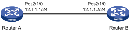
As shown in Figure 1, Router A and Router B are connected by POS interfaces.
Run HDLC on the link between them.
Configuration procedure
Configuring Router A
# Configure the clock mode of POS 2/1/0 as master.
<RouterA> system-view
[RouterA] interface pos 2/1/0
[RouterA-Pos2/1/0] clock master
# Enable HDLC encapsulation on POS 2/1/0.
[RouterA-Pos2/1/0] link-protocol hdlc
# Assign an IP address to POS 2/1/0.
[RouterA-Pos2/1/0] ip address 12.1.1.1 24
[RouterA-Pos2/1/0] quit
Configuring Router B
# Enable HDLC encapsulation on POS 2/1/0.
<RouterB> system-view
[RouterB] interface pos 2/1/0
[RouterB-Pos2/1/0] link-protocol hdlc
# Assign an IP address to POS 2/1/0.
[RouterB-Pos2/1/0] ip address 12.1.1.2 24
Verifying the configuration
# Ping a router from the other router, for example, ping Router B from Router A.
[RouterA] ping 12.1.1.2
Ping 12.1.1.2 (12.1.1.2): 56 data bytes, press CTRL_C to break
56 bytes from 12.1.1.2: icmp_seq=0 ttl=254 time=2.137 ms
56 bytes from 12.1.1.2: icmp_seq=1 ttl=254 time=2.051 ms
56 bytes from 12.1.1.2: icmp_seq=2 ttl=254 time=1.996 ms
56 bytes from 12.1.1.2: icmp_seq=3 ttl=254 time=1.963 ms
56 bytes from 12.1.1.2: icmp_seq=4 ttl=254 time=1.991 ms
--- Ping statistics for 12.1.1.2 ---
5 packet(s) transmitted, 5 packet(s) received, 0.0% packet loss
round-trip min/avg/max/std-dev = 1.963/2.028/2.137/0.062 ms
The output shows that Router A can successfully ping Router B.
Configuring HDLC link bundling
Overview
HDLC link bundling bundles multiple interfaces using HDLC encapsulation (also known as HDLC interfaces) together to form one logical link.
HDLC link bundling delivers the following benefits:
· Load balancing—Incoming/outgoing traffic is distributed across multiple HDLC link bundle member interfaces.
· Increased bandwidth—The bandwidth of the HDLC link bundle interface is the total bandwidth of all available member interfaces.
· Improved connection reliability—When a member interface goes down, the traffic on it automatically switches over to other available member interfaces. This avoids service interruption and improves the connection reliability of the whole HDLC link bundle.
Basic concepts
HDLC link bundle interface
An HDLC link bundle interface is a logical interface comprising a bundle of HDLC links.
HDLC link bundle
An HDLC link bundle is a group of HDLC interfaces. When you create an HDLC link bundle interface, an HDLC link bundle numbered the same as the HDLC link bundle interface is automatically generated.
Member interface
An interface assigned to an HDLC link bundle is called an HDLC link bundle member interface. Only POS interface and serial interfaces with HDLC encapsulation enabled can be assigned to an HDLC link bundle.
Member interfaces in an HDLC link bundle use the configuration on the HDLC link bundle interface to process Layer 3 services. All layer 3 service settings on the member interfaces, including the IP address, are void when the interfaces are assigned to the HDLC link bundle.
States of member interfaces
An HDLC link bundle member interface can be in one of the following states:
· Initial—The member interface is down at the link layer.
· Negotiated—The member interface is as follows:
¡ Up at the link layer.
¡ Does not meet the conditions for being a Selected interface in the HDLC link bundle.
· Ready—The member interface is as follows:
¡ Up at the link layer.
¡ Meets the conditions for being a Selected interface.
¡ Not Selected yet due to the following restrictions:
- The maximum number of Selected interfaces.
- The minimum number of Selected interfaces required for bringing up the HDLC link bundle.
- The minimum bandwidth required for bringing up the HDLC link bundle.
· Selected—The member interface is up at the link layer, meets the conditions for being Selected, and conforms to the restrictions. Only member interfaces in Selected state can forward traffic.
If an HDLC link bundle does not contain any Selected interfaces, the HDLC link bundle interface is brought down, and it cannot forward traffic. It will not be brought up and forward traffic until Selected interfaces are detected in the HDLC link bundle. The bandwidth of an HDLC link bundle interface is the total bandwidth of all Selected interfaces.
The states of HDLC link bundle member interfaces are determined according to the following rules:
1. An interface is placed in the Initial state if its link layer protocol is down.
2. An interface is placed in the Negotiated state when its link layer protocol goes up.
3. An interface in the Negotiated state might transit to the Selected or Ready state after completing the following selection process.
4. For example:
¡ The number of member interfaces in the Negotiated state is M.
¡ The maximum number of Selected interfaces allowed in the HDLC link bundle is set to N.
The maximum number of Selected member interfaces allowed in a bundle is set by using the bundle max-active links command. If the command is not set, the hardware capability 8 applies.
¡ When N is no smaller than M, all the member interfaces in the Negotiated state enter the Selected state.
¡ When N is smaller than M, these member interfaces are sorted as follows:
- They are first sorted in the descending order of rates/baud rates.
- Member interfaces with the same rate/baud rate are sorted in the descending order of bundling priorities.
- Member interfaces with the same bundling priority are sorted in the ascending order of interface numbers.
The first N member interfaces enter the Selected state, and the remaining (M-N) member interfaces enter the Ready state.
5. For example, the number of member interfaces meeting the conditions for being Selected is P. The minimum number of Selected interfaces required for bringing up the HDLC link bundle is set to Q.
The P interfaces will be Selected when any of the following conditions exist:
¡ P is not smaller than Q.
¡ The following limits are not set:
- Minimum number of Selected interfaces required for bringing up the HDLC link bundle.
- Minimum bandwidth required for bringing up the HDLC link bundle.
None of the P member interfaces will be Selected and they all stay in the Ready state when any of the following conditions exist:
¡ P is smaller than Q.
¡ The total bandwidths of the P member interfaces is smaller than the minimum bandwidth required for bringing up the HDLC link bundle.
Load balancing modes
An HDLC link bundle forwards traffic through its Selected interfaces. When multiple Selected interfaces exist in an HDLC link bundle, the device chooses the Selected interfaces to forward traffic according to its load balancing mode.
The following load balancing modes are available:
· Per-flow load balancing—Forwards packets of the same flow out of the same Selected interface. A flow is identified by match criteria.
¡ For IPv4 and IPv6 packets, the match criteria include source IP address and destination IP address.
¡ For MPLS packets, the match criteria are MPLS labels.
· Per-packet load balancing—Distributes packets evenly across all Selected interfaces by using the round-robin method.
Configuring an HDLC link bundle interface
Configuration restrictions and guidelines
When you configure an HDLC link bundle interface, follow these restrictions and guidelines:
· The minimum number of Selected interfaces required cannot be greater than the maximum number of Selected interfaces allowed in the HDLC link bundle.
· As a best practice to guarantee correct traffic transmission, configure each of the following parameters the same at both ends of an HDLC link bundle:
¡ Minimum number of Selected interfaces required for bringing up the HDLC link bundle.
¡ Maximum number of Selected interfaces allowed in the HDLC link bundle.
¡ Minimum bandwidth required for bringing up the HDLC link bundle.
· After the HDLC link bundle configuration is complete, the state of each member interface is determined again if you modify any of the following parameters:
¡ Minimum number of Selected interfaces required for bringing up the HDLC link bundle.
¡ Maximum number of Selected interfaces allowed in the HDLC link bundle.
¡ Minimum bandwidth required for bringing up the HDLC link bundle.
· As a best practice, set the same load balancing mode at both ends of an HDLC link bundle.
Configuration procedure
|
Step |
Command |
Remarks |
|
1. Enter system view. |
system-view |
N/A |
|
2. Create an HDLC link bundle interface and enter its view. |
interface hdlc-bundle bundle-id |
By default, no HDLC link bundle interface is created. |
|
3. Set the load balancing mode. |
bundle load-balance { per-flow | per-packet } |
By default, per-packet load balancing applies. |
|
4. (Optional.) Specify a primary traffic processing slot for the interface. |
· In standalone mode: · In IRF mode: |
By default, no primary traffic processing slot is specified for an interface. |
|
5. (Optional.) Specify a backup traffic processing slot for the interface. |
· In standalone mode: · In IRF mode: |
By default, no backup traffic processing slot is specified for an interface. |
|
6. (Optional.) Set the minimum number of Selected interfaces required for bringing up the HDLC link bundle. |
bundle min-active links number |
By default, the minimum number of Selected interfaces required for bringing up an HDLC link bundle is not set. |
|
7. (Optional.) Set the maximum number of Selected interfaces allowed in the HDLC link bundle. |
bundle max-active links number |
By default, the maximum number of Selected interfaces allowed in the HDLC link bundle is not set. |
|
8. (Optional.) Set the minimum bandwidth required for bringing up the HDLC link bundle. |
bundle min-active bandwidth bandwidth |
By default, the minimum bandwidth required for bringing up an HDLC link bundle is not set. |
|
9. (Optional.) Set the expected bandwidth for the HDLC link bundle interface. |
bandwidth bandwidth-value |
By default, the expected bandwidth (in kbps) is the interface baud rate divided by 1000. |
|
10. (Optional.) Set a description for the HDLC link bundle interface. |
description text |
By default, the description of an HDLC link bundle interface is the interface name followed by the Interface string. |
|
11. (Optional.) Set the MTU size for the HDLC link bundle interface. |
mtu size |
The default setting is 1500 bytes. The MTU size affects the fragmentation and reassembly of IP packets. Use this command to set a proper MTU size according to your network conditions. |
|
12. (Optional.) Restore the default settings for the HDLC link bundle interface. |
default |
N/A |
|
13. (Optional.) Bring up the HDLC link bundle interface |
undo shutdown |
By default, an HDLC link bundle interface is up. When an HDLC link bundle interface is brought up, the state of each member interface is re-determined. When an HDLC link bundle interface is shut down, the state of each Selected interface is placed into the Negotiated state. |
Assigning an interface to an HDLC link bundle
Configuration restrictions and guidelines
When you assign an interface to an HDLC link bundle, follow these restrictions and guidelines:
· An interface can belong to only one HDLC link bundle at any point in time. To assign a member interface to another HDLC link bundle, remove the interface from the current HDLC link bundle first.
· The link layer protocol of an interface to be assigned to an HDLC link bundle must be HDLC. After the interface is assigned to the HDLC link bundle, its link layer protocol cannot be changed.
· You can assign interfaces to a nonexistent HDLC link bundle as members.
· You can assign interfaces on different cards to the same HDLC link bundle.
· Changing the bundling priority of a member interface might cause the device to determine the state of each member interface.
· The peer interface directly connected to a local HDLC link bundle member interface must also join the same HDLC link bundle. A HDLC link bundle ID is locally significant. The ID on the peer device can be different from the local one.
· As a best practice, use the bundle member-priority command and the bundle max-active links command together to make sure that:
¡ Interconnected interfaces at both ends can be Selected.
¡ They can exchange traffic correctly.
Configuration procedure
|
Step |
Command |
Remarks |
|
1. Enter system view. |
system-view |
N/A |
|
2. Enter POS interface view or serial interface view. |
interface interface-type interface-number |
N/A |
|
3. Enable HDLC encapsulation on the interface. |
link-protocol hdlc |
By default, PPP encapsulation is enabled on an interface. |
|
4. Assign the interface to an HDLC link bundle. |
bundle id bundle-id |
By default, an interface is not assigned to any HDLC link bundle. |
|
5. Set the bundling priority for the member interface. |
bundle member-priority priority |
The default setting is 32768. |
Displaying and maintaining HDLC link bundling
Execute display commands in any view and reset commands in user view.
|
Task |
Command |
|
Display information about an HDLC link bundle (in standalone mode). |
display bundle hdlc-bundle [ bundle-id ] slot slot-number |
|
Display information about an HDLC link bundle (in IRF mode). |
display bundle hdlc-bundle [ bundle-id ] chassis chassis-number slot slot-number |
|
Display information about an HDLC link bundle interface. |
display interface [ hdlc-bundle [ bundle-id ] ] [ brief [ description | down ] ] |
|
Clear statistics for an HDLC link bundle interface. |
reset counters interface [ hdlc-bundle [ bundle-id ] ] |
HDLC link bundling configuration example
Network requirements
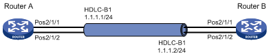
As shown in Figure 2, to increase bandwidth and enhance connection reliability between Router A and Router B, create an HDLC link bundle.
Configuring Router A
# Create HDLC link bundle interface 1 and assign an IP address to it.
<RouterA> system-view
[RouterA] interface hdlc-bundle 1
[RouterA-HDLC-bundle1] ip address 1.1.1.1 24
[RouterA-HDLC-bundle1] quit
# Assign POS interfaces POS 2/1/1 to HDLC link bundle 1, and configure the interface to use the master clock mode.
[RouterA] interface pos 2/1/1
[RouterA-Pos2/1/1] clock master
[RouterA-Pos2/1/1] link-protocol hdlc
[RouterA-Pos2/1/1] bundle id 1
[RouterA-Pos2/1/1] quit
# Assign POS interfaces POS 2/1/2 to HDLC link bundle 1, and configure the interface to use the master clock mode.
[RouterA] interface pos 2/1/2
[RouterA-Pos2/1/2] clock master
[RouterA-Pos2/1/2] link-protocol hdlc
[RouterA-Pos2/1/2] bundle id 1
[RouterA-Pos2/1/2] quit
Configuring Router B
# Create HDLC link bundle interface 1 and assign an IP address to it.
<RouterB> system-view
[RouterB] interface hdlc-bundle 1
[RouterB-HDLC-bundle1] ip address 1.1.1.2 24
[RouterB-HDLC-bundle1] quit
# Assign POS interfaces POS 2/1/1 to HDLC link bundle 1.
[RouterB] interface pos 2/1/1
[RouterB-Pos2/1/1] link-protocol hdlc
[RouterB-Pos2/1/1] bundle id 1
[RouterB-Pos2/1/1] quit
# Assign POS interfaces POS 2/1/2 to HDLC link bundle 1.
[RouterB] interface pos 2/1/2
[RouterB-Pos2/1/2] link-protocol hdlc
[RouterB-Pos2/1/2] bundle id 1
[RouterB-Pos2/1/2] quit
Verifying the configuration
# Verify that the HDLC link bundle interfaces on Router A and Router B can ping each other.
[RouterA] ping –a 1.1.1.1 1.1.1.2
Ping 1.1.1.2 (1.1.1.2) from 1.1.1.1: 56 data bytes, press CTRL_C to break
56 bytes from 1.1.1.2: icmp_seq=0 ttl=255 time=0.000 ms
56 bytes from 1.1.1.2: icmp_seq=1 ttl=255 time=0.000 ms
56 bytes from 1.1.1.2: icmp_seq=2 ttl=255 time=0.000 ms
56 bytes from 1.1.1.2: icmp_seq=3 ttl=255 time=0.000 ms
56 bytes from 1.1.1.2: icmp_seq=4 ttl=255 time=0.000 ms
--- Ping statistics for 1.1.1.2 ---
5 packet(s) transmitted, 5 packet(s) received, 0.0% packet loss
round-trip min/avg/max/std-dev = 0.000/0.000/0.000/0.000 ms
# Verify that:
· POS 2/1/1 and POS 2/1/2 are in Selected state and can perform load balancing.
· The bandwidth of the HDLC link bundle is 1244160 kbps, the total bandwidth of two POS interfaces.
· When one POS interface fails, the traffic can be forwarded through the other POS interface. This improves the link reliability.
Use Router A as an example.
[RouterA] display bundle hdlc-bundle 1
Bundle: HDLC-bundle1
Selected members: 2, Total bandwidth: 1244160 kbps
Member State Bandwidth(kbps) Priority
Pos2/1/1 Selected 622080 32768
Pos2/1/2 Selected 622080 32768
