- Table of Contents
-
- 10-Security Configuration Guide
- 00-Preface
- 01-AAA configuration
- 02-802.1X configuration
- 03-MAC authentication configuration
- 04-Portal configuration
- 05-Port security configuration
- 06-Password control configuration
- 07-Keychain configuration
- 08-Public key management
- 09-PKI configuration
- 10-IPsec configuration
- 11-SSH configuration
- 12-SSL configuration
- 13-Attack detection and prevention configuration
- 14-TCP attack prevention configuration
- 15-IP source guard configuration
- 16-ARP attack protection configuration
- 17-ND attack defense configuration
- 18-uRPF configuration
- 19-MFF configuration
- 20-FIPS configuration
- 21-MACsec configuration
- 22-802.1X client configuration
- 23-Web authentication configuration
- 24-Triple authentication configuration
- Related Documents
-
| Title | Size | Download |
|---|---|---|
| 19-MFF configuration | 178.39 KB |
Enabling periodic gateway probe
Specifying the IP addresses of servers
Displaying and maintaining MFF
Auto-mode MFF configuration example in a tree network
Auto-mode MFF configuration example in a ring network
Manual-mode MFF configuration example in a tree network
Manual-mode MFF configuration example in a ring network
Configuring MFF
Overview
MAC-forced forwarding (MFF) implements Layer 2 isolation and Layer 3 communication between hosts in the same broadcast domain.
An MFF-enabled device intercepts ARP requests and returns the MAC address of a gateway (or server) to the senders. In this way, the senders are forced to send packets to the gateway for traffic monitoring and attack prevention.
|
|
NOTE: MFF does not support VRRPE for a gateway. |
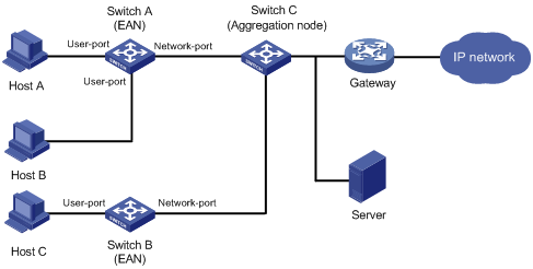
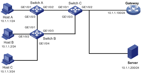
As shown in Figure 1, hosts are connected to Switch C through Switch A and Switch B, which are called Ethernet access nodes (EANs). The MFF-enabled EANs forward packets from hosts to the gateway for further forwarding. The hosts are isolated at Layer 2, but they can communicate at Layer 3.
An MFF-enabled device and a host cannot ping each other.
Figure 1 Network diagram for MFF
MFF works with any of the following features to implement traffic filtering and Layer 2 isolation on the EANs:
· DHCP snooping (see Layer 3—IP Services Configuration Guide).
· ARP snooping (see Layer 3—IP Services Configuration Guide).
· IP source guard (see "Configuring IP source guard).
· ARP detection (see "Configuring ARP attack protection").
· VLAN mapping (see Layer 2—LAN Switching Configuration Guide).
|
|
NOTE: When MFF works with static IP source guard bindings, you must configure VLAN IDs in the static bindings. Otherwise, IP packets allowed by IP source guard are permitted even if their destination MAC addresses are not the MAC address of the gateway. |
Basic concepts
An MFF-enabled device has two types of ports: user port and network port.
User port
An MFF user port is directly connected to a host and processes the following packets differently:
· Allows DHCP packets and multicast packets to pass.
· Delivers ARP packets to the CPU.
· After learning gateways' MAC addresses, a user port allows only the unicast packets with the gateways' MAC addresses as the destination MAC addresses to pass. If no gateways' MAC addresses are learned, a user port discards all received unicast packets.
Network port
An MFF network port is connected to any of the following networking devices:
· An access switch.
· A distribution switch.
· A gateway.
· A server.
A network port processes the following packets differently:
· Allows multicast packets and DHCP packets to pass.
· Delivers ARP packets to the CPU.
· Denies broadcast packets other than DHCP and ARP packets.
You need to configure the following ports as network ports:
· Upstream ports connected to a gateway.
· Ports connected to the MFF devices in a cascaded network (a network with multiple MFF devices connected to one another).
· Ports between devices in a ring network.
Link aggregation is supported by network ports in an MFF-enabled VLAN, but it is not supported by user ports in the VLAN. You can add the network ports to link aggregation groups, but cannot add the user ports to link aggregation groups. For more information about link aggregation, see Layer 2—LAN Switching Configuration Guide.
|
|
NOTE: · A network port is not always an upstream port. · If you enable MFF for a VLAN, each port in the VLAN must be a network or user port. |
MFF operation modes
Manual mode
The manual mode applies to networks where the hosts' IP addresses are manually configured. The hosts cannot obtain the gateway information through DHCP. VLAN maintains only the MAC address of the default gateway.
After receiving an ARP request for a host's MAC address from the gateway, the MFF device directly replies the host's MAC address to the gateway according to the ARP snooping entries. After learning the gateway's MAC address, the MFF device updates the MAC address upon receiving an ARP packet with a different sender MAC address from the default gateway.
Automatic mode
The automatic mode applies to networks that allocate IP addresses to hosts through DHCP.
In automatic mode, the device configured with DHCP snooping resolves Option 3 (Router IP option) in the received DHCP ACK message to obtain a gateway for the DHCP snooping entry. If the DHCP ACK message contains multiple gateway addresses, only the first one is recorded for the entry. If the message contains no gateway IP address, the first gateway recorded by the current VLAN is used.
If the sender MAC address of an ARP packet from a gateway is different from the MAC address recorded for the gateway, the MFF device updates the gateway's MAC address.
|
|
NOTE: In MFF automatic mode, a VLAN can learn and maintain a maximum of 20 gateways. The gateway IP addresses will not be updated, and the gateway information does not age out unless MFF is disabled. |
MFF working mechanism
An MFF-enabled device implements Layer 3 communication between hosts by intercepting ARP requests from the hosts and replies with the MAC address of a gateway. This mechanism helps reduce the number of broadcast messages.
The MFF device processes ARP packets as follows:
· After receiving an ARP request from a host, the MFF device sends the MAC address of the corresponding gateway to the host. In this way, hosts in the network have to communicate at Layer 3 through a gateway.
· After receiving an ARP request from a gateway, the MFF device sends the requested host's MAC address to the gateway if the corresponding entry is available. If the entry is not available, the MFF device forwards the ARP request.
· The MFF device forwards ARP replies between hosts and gateways.
· If the source MAC addresses of ARP requests from gateways are different from those recorded, the MFF device updates and broadcasts the IP and MAC addresses of the gateways.
Protocols and standards
RFC 4562, MAC-Forced Forwarding
Configuring MFF
Enabling MFF
For MFF to take effect in manual mode, make sure ARP snooping is enabled on the device.
For MFF to take effect in automatic mode, make sure DHCP snooping is enabled on the device and DHCP snooping trusted ports are configured.
To enable MFF and specify an MFF operating mode:
|
Step |
Command |
Remarks |
|
1. Enter system view. |
system-view |
N/A |
|
2. Enter VLAN view. |
vlan vlan-id |
N/A |
|
3. Enable MFF. |
· Enable automatic mode: · Enable manual mode: |
By default, MFF is disabled. |
Configuring a network port
|
Step |
Command |
Remarks |
|
1. Enter system view. |
system-view |
N/A |
|
2. Enter Layer 2 Ethernet interface view or Layer 2 aggregate interface view. |
· Enter Layer 2 Ethernet interface view: · Enter Layer 2 aggregate interface view: |
N/A |
|
3. Configure the port as a network port. |
mac-forced-forwarding network-port |
By default, the port is a user port. |
Enabling periodic gateway probe
You can configure the MFF device to detect gateways every 30 seconds for the change of MAC addresses by sending forged ARP packets. The ARP packets use 0.0.0.0 as the sender IP address and bridge MAC address as the sender MAC address.
This feature is supported by MFF in both manual and automatic modes.
To enable periodic gateway probe:
|
Step |
Command |
Remarks |
|
1. Enter system view. |
system-view |
N/A |
|
2. Enter VLAN view. |
vlan vlan-id |
N/A |
|
3. Enable periodic gateway probe. |
mac-forced-forwarding gateway probe |
By default, this feature is disabled. |
Specifying the IP addresses of servers
Perform this task to ensure communication between the servers and clients.
Specify the IP addresses of the following items if they are in the network:
· DHCP servers.
· Servers providing some other service.
· Interfaces on a router in a VRRP group.
When the MFF device receives an ARP request from a server, the device searches IP-to-MAC address entries it has stored. Then the device replies with the requested MAC address to the server.
As a result, packets from a host to a server are forwarded by the gateway. However, packets from a server to a host are not forwarded by the gateway.
MFF does not check whether the IP address of a server is on the same network segment as that of a gateway. Instead, it checks whether the IP address of a server is all-zero or all-one. An all-zero or all-one server IP address is invalid.
You can specify a server's IP address in either manual or automatic MFF mode.
To specify the IP addresses of servers:
|
Step |
Command |
Remarks |
|
1. Enter system view. |
system-view |
N/A |
|
2. Enter VLAN view. |
vlan vlan-id |
N/A |
|
3. Specify the IP addresses of servers. |
mac-forced-forwarding server server-ip&<1-10> |
By default, no server IP address is specified. If the server's interface connecting to the MFF device uses secondary IP addresses to send ARP packets, include all these IP addresses in the server IP address list. |
Displaying and maintaining MFF
Execute display commands in any view.
|
Task |
Command |
|
Display MFF port configuration. |
display mac-forced-forwarding interface |
|
Display the MFF configuration for a VLAN. |
display mac-forced-forwarding vlan vlan-id |
MFF configuration examples
Auto-mode MFF configuration example in a tree network
Network requirements
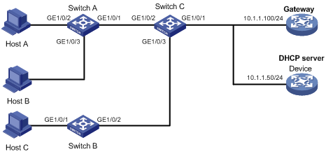
As shown in Figure 2, all the devices are in VLAN 100. Hosts A, B, and C obtain IP addresses from the DHCP server.
Configure MFF to isolate the hosts at Layer 2 and allow them to communicate with each other through the gateway at Layer 3.
Configuration procedure
1. Configure the IP addresses of the gateway and the DHCP server, as shown in Figure 2.
2. Configure Switch A:
# Enable DHCP snooping.
<SwitchA> system-view
[SwitchA] dhcp snooping enable
# Enable MFF in automatic mode on VLAN 100.
[SwitchA] vlan 100
[SwitchA-vlan100] mac-forced-forwarding auto
[SwitchA-vlan100] quit
# Configure IP address 10.1.1.50 for the DHCP server.
[SwitchA-vlan100] mac-forced-forwarding server 10.1.1.50
# Configure GigabitEthernet 1/0/1 as a network port.
[SwitchA] interface gigabitethernet 1/0/1
[SwitchA-GigabitEthernet1/0/1] mac-forced-forwarding network-port
# Configure GigabitEthernet 1/0/1 as a DHCP snooping trusted port.
[SwitchA-GigabitEthernet1/0/1] dhcp snooping trust
3. Configure Switch B:
# Enable DHCP snooping.
<SwitchB> system-view
[SwitchB] dhcp snooping enable
# Enable MFF in automatic mode on VLAN 100.
[SwitchB] vlan 100
[SwitchB-vlan100] mac-forced-forwarding auto
[SwitchB-vlan100] quit
# Configure IP address 10.1.1.50 for the DHCP server.
[SwitchB-vlan100] mac-forced-forwarding server 10.1.1.50
# Configure GigabitEthernet 1/0/2 as a network port.
[SwitchB] interface gigabitethernet 1/0/2
[SwitchB-GigabitEthernet1/0/2] mac-forced-forwarding network-port
# Configure GigabitEthernet 1/0/2 as a DHCP snooping trusted port.
[SwitchB-GigabitEthernet1/0/2] dhcp snooping trust
Auto-mode MFF configuration example in a ring network
Network requirements
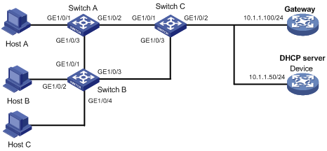
As shown in Figure 3, all the devices are in VLAN 100, and the switches form a ring. Hosts A, B, and C obtain IP addresses from the DHCP server.
Configure MFF to isolate the hosts at Layer 2 and allow them to communicate with each other through the gateway at Layer 3.
Configuration procedure
1. Configure the IP addresses of the gateway and the DHCP server, as shown in Figure 3.
2. Configure Switch A:
# Enable DHCP snooping.
<SwitchA> system-view
[SwitchA] dhcp snooping enable
# Enable STP globally to make sure STP is enabled on interfaces.
[SwitchA] stp global enable
# Enable MFF in automatic mode on VLAN 100.
[SwitchA] vlan 100
[SwitchA-vlan100] mac-forced-forwarding auto
[SwitchA-vlan100] quit
# Assign IP address 10.1.1.50 to the DHCP server.
[SwitchA-vlan100] mac-forced-forwarding server 10.1.1.50
# Configure GigabitEthernet 1/0/2 as a network port.
[SwitchA] interface gigabitethernet 1/0/2
[SwitchA-GigabitEthernet1/0/2] mac-forced-forwarding network-port
# Configure GigabitEthernet 1/0/2 as a DHCP snooping trusted port.
[SwitchA-GigabitEthernet1/0/2] dhcp snooping trust
[SwitchA-GigabitEthernet1/0/2] quit
# Configure GigabitEthernet 1/0/3 as a network port.
[SwitchA] interface gigabitethernet 1/0/3
[SwitchA-GigabitEthernet1/0/3] mac-forced-forwarding network-port
# Configure GigabitEthernet 1/0/3 as a DHCP snooping trusted port.
[SwitchA-GigabitEthernet1/0/3] dhcp snooping trust
3. Configure Switch B:
# Enable DHCP snooping.
<SwitchB> system-view
[SwitchB] dhcp-snooping
# Enable STP globally to make sure STP is enabled on interfaces.
[SwitchB] stp global enable
# Enable MFF in automatic mode on VLAN 100.
[SwitchB] vlan 100
[SwitchB-vlan100] mac-forced-forwarding auto
[SwitchB-vlan100] quit
# Configure IP address 10.1.1.50 for the DHCP server.
[SwitchB-vlan100] mac-forced-forwarding server 10.1.1.50
# Configure GigabitEthernet 1/0/1 as a network port.
[SwitchB] interface gigabitethernet 1/0/1
[SwitchB-GigabitEthernet1/0/1] mac-forced-forwarding network-port
# Configure GigabitEthernet 1/0/1 as a DHCP snooping trusted port.
[SwitchB-GigabitEthernet1/0/1] dhcp snooping trust
[SwitchB-GigabitEthernet1/0/1] quit
# Configure GigabitEthernet 1/0/3 as a network port.
[SwitchB] interface gigabitethernet 1/0/3
[SwitchB-GigabitEthernet1/0/3] mac-forced-forwarding network-port
# Configure GigabitEthernet 1/0/3 as a DHCP snooping trusted port.
[SwitchB-GigabitEthernet1/0/3] dhcp snooping trust
4. Enable STP on Switch C globally to make sure STP is enabled on interfaces.
<SwitchC> system-view
Manual-mode MFF configuration example in a tree network
Network requirements
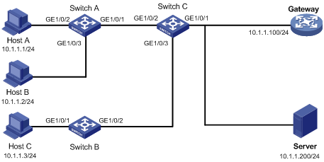
As shown in Figure 4, all the devices are in VLAN 100. Hosts A, B, and C are assigned IP addresses manually.
Configure MFF to isolate the hosts at Layer 2 and allow them to communicate with each other through the gateway at Layer 3.
Configuration procedure
1. Configure the IP addresses of the hosts and the gateway, as shown in Figure 4.
2. Configure Switch A:
# Configure manual-mode MFF on VLAN 100.
[SwitchA] vlan 100
[SwitchA-vlan100] mac-forced-forwarding default-gateway 10.1.1.100
# Specify the IP address of the server.
[SwitchA-vlan100] mac-forced-forwarding server 10.1.1.200
# Enable ARP snooping on VLAN 100.
[SwitchA-vlan100] arp snooping enable
[SwitchA-vlan100] quit
# Configure GigabitEthernet 1/0/1 as a network port.
[SwitchA] interface gigabitethernet 1/0/1
[SwitchA-GigabitEthernet1/0/1] mac-forced-forwarding network-port
3. Configure Switch B:
# Configure manual-mode MFF on VLAN 100.
[SwitchB] vlan 100
[SwitchB-vlan100] mac-forced-forwarding default-gateway 10.1.1.100
# Specify the IP address of the server.
[SwitchB-vlan100] mac-forced-forwarding server 10.1.1.200
# Enable ARP snooping on VLAN 100.
[SwitchB-vlan100] arp snooping enable
[SwitchB-vlan100] quit
# Configure GigabitEthernet 1/0/2 as a network port.
[SwitchB] interface gigabitethernet 1/0/2 1/0/6
[SwitchB-GigabitEthernet1/0/2] mac-forced-forwarding network-port
Manual-mode MFF configuration example in a ring network
Network requirements
As shown in Figure 5, all the devices are in VLAN 100, and the switches form a ring. Hosts A, B, and C are assigned IP addresses manually.
Configure MFF to isolate the hosts at Layer 2 and allow them to communicate with each other through the gateway at Layer 3.
Configuration procedure
1. Configure the IP addresses of the hosts and the gateway, as in shown in Figure 5.
2. Configure Switch A:
# Enable STP globally to make sure STP is enabled on interfaces.
[SwitchA] stp global enable
# Configure manual-mode MFF on VLAN 100.
[SwitchA] vlan 100
[SwitchA-vlan100] mac-forced-forwarding default-gateway 10.1.1.100
# Specify the IP address of the server.
[SwitchA-vlan100] mac-forced-forwarding server 10.1.1.200
# Enable ARP snooping on VLAN 100.
[SwitchA-vlan100] arp snooping enable
[SwitchA-vlan100] quit
# Configure GigabitEthernet 1/0/2 and GigabitEthernet 1/0/3 as network ports.
[SwitchA] interface gigabitethernet 1/0/2
[SwitchA-GigabitEthernet1/0/2] mac-forced-forwarding network-port
[SwitchA-GigabitEthernet1/0/2] quit
[SwitchA] interface gigabitethernet 1/0/3
[SwitchA-GigabitEthernet1/0/3] mac-forced-forwarding network-port
3. Configure Switch B:
# Enable STP globally to make sure STP is enabled on interfaces.
[SwitchB] stp global enable
# Configure manual-mode MFF on VLAN 100.
[SwitchB] vlan 100
[SwitchB-vlan100] mac-forced-forwarding default-gateway 10.1.1.100
# Specify the IP address of the server.
[SwitchB-vlan100] mac-forced-forwarding server 10.1.1.200
# Enable ARP snooping on VLAN 100.
[SwitchB-vlan100] arp snooping enable
[SwitchB-vlan100] quit
# Configure GigabitEthernet 1/0/1 and GigabitEthernet 1/0/3 as network ports.
[SwitchB] interface gigabitethernet 1/0/1
[SwitchB-GigabitEthernet1/0/1] mac-forced-forwarding network-port
[SwitchB-GigabitEthernet1/0/1] quit
[SwitchB] interface gigabitethernet 1/0/3
[SwitchB-GigabitEthernet1/0/3] mac-forced-forwarding network-port
4. Enable STP on Switch C globally to make sure STP is enabled on interfaces.
<SwitchC> system-view
[SwitchC] stp global enable