- Table of Contents
-
- 10-Security Configuration Guide
- 00-Preface
- 01-AAA configuration
- 02-802.1X configuration
- 03-MAC authentication configuration
- 04-Portal configuration
- 05-Port security configuration
- 06-Password control configuration
- 07-Keychain configuration
- 08-Public key management
- 09-PKI configuration
- 10-IPsec configuration
- 11-SSH configuration
- 12-SSL configuration
- 13-Attack detection and prevention configuration
- 14-TCP attack prevention configuration
- 15-IP source guard configuration
- 16-ARP attack protection configuration
- 17-ND attack defense configuration
- 18-uRPF configuration
- 19-MFF configuration
- 20-FIPS configuration
- 21-MACsec configuration
- 22-802.1X client configuration
- 23-Web authentication configuration
- 24-Triple authentication configuration
- Related Documents
-
| Title | Size | Download |
|---|---|---|
| 02-802.1X configuration | 526.21 KB |
Controlled/uncontrolled port and port authorization status
802.1X authentication initiation
802.1X client as the initiator
Access device as the initiator
802.1X authentication procedures
Comparing EAP relay and EAP termination
Using 802.1X authentication with other features
802.1X configuration task list
Enabling EAP relay or EAP termination
Setting the port authorization state
Specifying an access control method
Setting the maximum number of concurrent 802.1X users on a port
Setting the maximum number of authentication request attempts
Setting the 802.1X authentication timeout timers
Configuring online user handshake
Configuring the authentication trigger feature
Specifying a mandatory authentication domain on a port
Configuring 802.1X reauthentication
Configuration restrictions and guidelines
Configuring 802.1X periodic reauthentication
Configuring 802.1X manual reauthentication
Enabling the keep-online feature
Configuring an 802.1X guest VLAN
Enabling 802.1X guest VLAN assignment delay
Configuring an 802.1X Auth-Fail VLAN
Configuring an 802.1X critical VLAN
Enabling the 802.1X critical voice VLAN
Configuration restrictions and guidelines
Specifying supported domain name delimiters
Enabling 802.1X user IP freezing
Sending 802.1X protocol packets out of a port without VLAN tags
Setting the maximum number of 802.1X authentication attempts for MAC authenticated users
Configuring the EAD assistant feature
Displaying and maintaining 802.1X
802.1X authentication configuration examples
Basic 802.1X authentication configuration example
802.1X guest VLAN and authorization VLAN configuration example
802.1X with ACL assignment configuration example
802.1X with EAD assistant configuration example (with DHCP relay agent)
802.1X with EAD assistant configuration example (with DHCP server)
802.1X SmartOn configuration example
EAD assistant URL redirection failure
802.1X overview
802.1X is a port-based network access control protocol initially proposed for securing WLANs. The protocol has also been widely used on Ethernet networks for access control.
802.1X controls network access by authenticating the devices connected to 802.1X-enabled LAN ports.
802.1X architecture
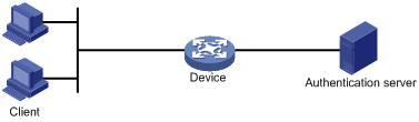
802.1X operates in the client/server model. As shown in Figure 1, 802.1X authentication includes the following entities:
· Client (supplicant)—A user terminal seeking access to the LAN. The terminal must have 802.1X software to authenticate to the access device.
· Access device (authenticator)—Authenticates the client to control access to the LAN. In a typical 802.1X environment, the access device uses an authentication server to perform authentication.
· Authentication server—Provides authentication services for the access device. The authentication server first authenticates 802.1X clients by using the data sent from the access device. Then, the server returns the authentication results to the access device to make access decisions. The authentication server is typically a RADIUS server. In a small LAN, you can use the access device as the authentication server.
Controlled/uncontrolled port and port authorization status
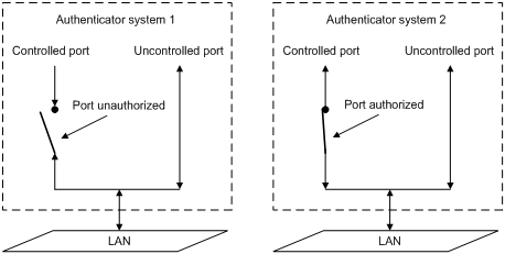
802.1X defines two logical ports for the network access port: controlled port and uncontrolled port. Any packet arriving at the network access port is visible to both logical ports.
· Uncontrolled port—Is always open to receive and transmit authentication packets.
· Controlled port—Filters packets depending on the port state.
¡ Authorized state—The controlled port is in authorized state when the client has passed authentication. The port allows traffic to pass through.
¡ Unauthorized state—The port is in unauthorized state when the client has failed authentication. The port controls traffic by using one of the following methods:
- Performs bidirectional traffic control to deny traffic to and from the client.
- Performs unidirectional traffic control to deny traffic from the client. The H3C devices support only unidirectional traffic control.
Figure 2 Authorization state of a controlled port
802.1X-related protocols
802.1X uses the Extensible Authentication Protocol (EAP) to transport authentication information for the client, the access device, and the authentication server. EAP is an authentication framework that uses the client/server model. The framework supports a variety of authentication methods, including MD5-Challenge, EAP-Transport Layer Security (EAP-TLS), and Protected EAP (PEAP).
802.1X defines EAP over LAN (EAPOL) for passing EAP packets between the client and the access device over a wired or wireless LAN. Between the access device and the authentication server, 802.1X delivers authentication information by using one of the following methods:
· Encapsulates EAP packets in RADIUS by using EAP over RADIUS (EAPOR), as described in "EAP relay."
· Extracts authentication information from the EAP packets and encapsulates the information in standard RADIUS packets, as described in "EAP termination."
Packet formats
EAP packet format
Figure 3 shows the EAP packet format.
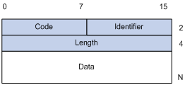
· Code—Type of the EAP packet. Options include Request (1), Response (2), Success (3), or Failure (4).
· Identifier—Used for matching Responses with Requests.
· Length—Length (in bytes) of the EAP packet. The EAP packet length is the sum of the Code, Identifier, Length, and Data fields.
· Data—Content of the EAP packet. This field appears only in a Request or Response EAP packet. The Data field contains the request type (or the response type) and the type data. Type 1 (Identity) and type 4 (MD5-Challenge) are two examples for the type field.
EAPOL packet format
Figure 4 shows the EAPOL packet format.
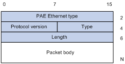
· PAE Ethernet type—Protocol type. It takes the value 0x888E for EAPOL.
· Protocol version—The EAPOL protocol version used by the EAPOL packet sender.
· Type—Type of the EAPOL packet. Table 1 lists the types of EAPOL packets supported by H3C implementation of 802.1X.
Table 1 Types of EAPOL packets
|
Value |
Type |
Description |
|
0x00 |
EAP-Packet |
The client and the access device uses EAP-Packets to transport authentication information. |
|
0x01 |
EAPOL-Start |
The client sends an EAPOL-Start message to initiate 802.1X authentication to the access device. |
|
0x02 |
EAPOL-Logoff |
The client sends an EAPOL-Logoff message to tell the access device that the client is logging off. |
· Length—Data length in bytes, or length of the Packet body. If packet type is EAPOL-Start or EAPOL-Logoff, this field is set to 0, and no Packet body field follows.
· Packet body—Content of the packet. When the EAPOL packet type is EAP-Packet, the Packet body field contains an EAP packet.
EAP over RADIUS
RADIUS adds two attributes, EAP-Message and Message-Authenticator, for supporting EAP authentication. For the RADIUS packet format, see "Configuring AAA."
EAP-Message
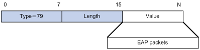
RADIUS encapsulates EAP packets in the EAP-Message attribute, as shown in Figure 5. The Type field takes 79, and the Value field can be up to 253 bytes. If an EAP packet is longer than 253 bytes, RADIUS encapsulates it in multiple EAP-Message attributes.
Figure 5 EAP-Message attribute format
Message-Authenticator
As shown in Figure 6, RADIUS includes the Message-Authenticator attribute in all packets that have an EAP-Message attribute to check their integrity. The packet receiver drops the packet if the calculated packet integrity checksum is different from the Message-Authenticator attribute value. The Message-Authenticator prevents EAP authentication packets from being tampered with during EAP authentication.
Figure 6 Message-Authenticator attribute format
![]()
802.1X authentication initiation
Both the 802.1X client and the access device can initiate 802.1X authentication.
802.1X client as the initiator
The client sends an EAPOL-Start packet to the access device to initiate 802.1X authentication. The destination MAC address of the packet is the IEEE 802.1X specified multicast address 01-80-C2-00-00-03 or the broadcast MAC address. If any intermediate device between the client and the authentication server does not support the multicast address, you must use an 802.1X client that can send broadcast EAPOL-Start packets. For example, you can use the H3C iNode 802.1X client.
Access device as the initiator
The access device initiates authentication, if a client cannot send EAPOL-Start packets. One example is the 802.1X client available with Windows XP.
The access device supports the following modes:
· Multicast trigger mode—The access device multicasts EAP-Request/Identity packets to initiate 802.1X authentication at the identity request interval.
· Unicast trigger mode—Upon receiving a frame from an unknown MAC address, the access device sends an EAP-Request/Identity packet out of the receiving port to the MAC address. The device retransmits the packet if no response has been received within the identity request timeout interval. This process continues until the maximum number of request attempts set by using the dot1x retry command is reached.
The username request timeout timer sets both the identity request interval for the multicast trigger and the identity request timeout interval for the unicast trigger.
802.1X authentication procedures
802.1X authentication has two methods: EAP relay and EAP termination. You choose either mode depending on support of the RADIUS server for EAP packets and EAP authentication methods.
· EAP relay mode.
EAP relay is defined in IEEE 802.1X. In this mode, the network device uses EAPOR packets to send authentication information to the RADIUS server, as shown in Figure 7.
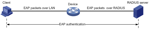
In EAP relay mode, the client must use the same authentication method as the RADIUS server. On the access device, you only need to use the dot1x authentication-method eap command to enable EAP relay.
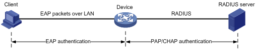
· EAP termination mode.
As shown in Figure 8, the access device performs the following operations in EAP termination mode:
a. Terminates the EAP packets received from the client.
b. Encapsulates the client authentication information in standard RADIUS packets.
c. Uses PAP or CHAP to authenticate to the RADIUS server.
Comparing EAP relay and EAP termination
|
Packet exchange method |
Benefits |
Limitations |
|
EAP relay |
· Supports various EAP authentication methods. · The configuration and processing are simple on the access device. |
The RADIUS server must support the EAP-Message and Message-Authenticator attributes, and the EAP authentication method used by the client. |
|
EAP termination |
Works with any RADIUS server that supports PAP or CHAP authentication. |
· Supports only the following EAP authentication methods: ¡ MD5-Challenge EAP authentication. ¡ The username and password EAP authentication initiated by an H3C iNode 802.1X client. · The processing is complex on the access device. |
EAP relay
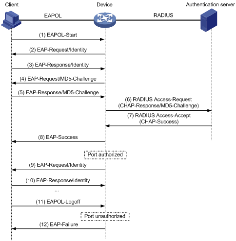
Figure 9 shows the basic 802.1X authentication procedure in EAP relay mode, assuming that EAP-MD5 is used.
Figure 9 802.1X authentication procedure in EAP relay mode
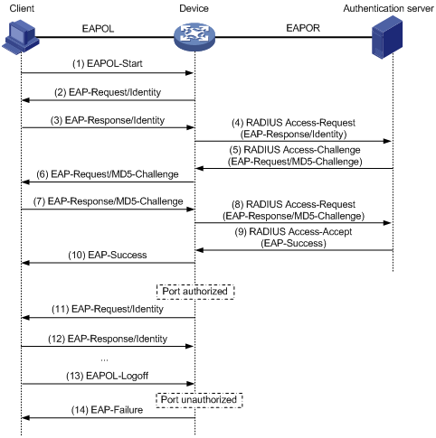
The following steps describe the 802.1X authentication procedure:
1. When a user launches the 802.1X client and enters a registered username and password, the 802.1X client sends an EAPOL-Start packet to the access device.
2. The access device responds with an EAP-Request/Identity packet to ask for the client username.
3. In response to the EAP-Request/Identity packet, the client sends the username in an EAP-Response/Identity packet to the access device.
4. The access device relays the EAP-Response/Identity packet in a RADIUS Access-Request packet to the authentication server.
5. The authentication server uses the identity information in the RADIUS Access-Request to search its user database. If a matching entry is found, the server uses a randomly generated challenge (EAP-Request/MD5-Challenge) to encrypt the password in the entry. Then, the server sends the challenge in a RADIUS Access-Challenge packet to the access device.
6. The access device transmits the EAP-Request/MD5-Challenge packet to the client.
7. The client uses the received challenge to encrypt the password, and sends the encrypted password in an EAP-Response/MD5-Challenge packet to the access device.
8. The access device relays the EAP-Response/MD5-Challenge packet in a RADIUS Access-Request packet to the authentication server.
9. The authentication server compares the received encrypted password with the encrypted password it generated at step 5. If the two passwords are identical, the server considers the client valid and sends a RADIUS Access-Accept packet to the access device.
10. Upon receiving the RADIUS Access-Accept packet, the access device performs the following operations:
a. Sends an EAP-Success packet to the client.
b. Sets the controlled port in authorized state.
The client can access the network.
11. After the client comes online, the access device periodically sends handshake requests to check whether the client is still online. By default, if two consecutive handshake attempts fail, the device logs off the client.
13. The client can also send an EAPOL-Logoff packet to ask the access device for a logoff.
14. In response to the EAPOL-Logoff packet, the access device changes the status of the controlled port from authorized to unauthorized. Then, the access device sends an EAP-Failure packet to the client.
EAP termination
Figure 10 shows the basic 802.1X authentication procedure in EAP termination mode, assuming that CHAP authentication is used.
Figure 10 802.1X authentication procedure in EAP termination mode
In EAP termination mode, the access device rather than the authentication server generates an MD5 challenge for password encryption. The access device then sends the MD5 challenge together with the username and encrypted password in a standard RADIUS packet to the RADIUS server.
Configuring 802.1X
This chapter describes how to configure 802.1X on an H3C device. You can also configure the port security feature to perform 802.1X. Port security combines and extends 802.1X and MAC authentication. It applies to a network, a WLAN, for example, that requires different authentication methods for different users on a port. For more information about the port security feature, see "Configuring port security."
Access control methods
H3C implements port-based access control as defined in the 802.1X protocol, and extends the protocol to support MAC-based access control.
· Port-based access control—Once an 802.1X user passes authentication on a port, any subsequent user can access the network through the port without authentication. When the authenticated user logs off, all other users are logged off.
· MAC-based access control—Each user is separately authenticated on a port. When a user logs off, no other online users are affected.
802.1X VLAN manipulation
Authorization VLAN
The device uses the authorization VLAN to control the access of an 802.1X user to authorized network resources.
Supported VLAN types and forms
Which VLAN types and forms are supported depends on the authorization type.
· Local VLAN authorization.
The authorization VLAN of an 802.1X user is specified in user view or user group view in the form of VLAN ID on the device. The port through which the user accesses the device is assigned to the VLAN as an untagged member. Tagged VLAN assignment is not supported.
For more information about local user configuration, see "Configuring AAA."
· Remote VLAN authorization.
· The authorization VLAN information of an 802.1X user is assigned by a remote server. The device resolves the VLAN information and selects a VLAN as the authorization VLAN for the user. The port through which the user accesses the device can be assigned to the VLAN as a tagged or untagged member.
· The access device can resolve server-assigned VLANs in the following forms:
¡ VLAN ID.
¡ VLAN name.
The VLAN name represents the VLAN description on the access device.
¡ Combination of VLAN IDs and VLAN names.
In the string, some VLANs are represented by their IDs, and some VLANs are represented by their names.
¡ VLAN group name.
For more information about VLAN groups, see Layer 2—LAN Switching Configuration Guide.
¡ VLAN ID with suffix.
The suffix can be t or u, which indicates whether the ports assigned to the VLAN are tagged members or not. For example, 2u indicates that the ports assigned to VLAN 2 are untagged members.
|
|
NOTE: The access device converts VLAN names and VLAN group name into VLAN IDs before VLAN assignment. |
Unsupported VLAN types
Do not specify the following types of VLANs for VLAN authorization. The access device does not assign these VLANs to 802.1X users.
· VLANs that have not been created.
· Dynamically-learnt VLANs.
· Reserved VLANs.
· Super VLANs.
· Private VLANs.
VLAN selection and assignment
If the server assigns a group of VLANs, the access device selects and assigns a VLAN according to the VLAN ID format. Table 2 describes the VLAN selection and assignment rules for a group of authorization VLANs.
Table 2 VLAN selection and assignment for a group of authorization VLANs
|
Types of authorized VLANs |
VLAN selection and assignment rules |
|
· VLANs by IDs · VLANs by names · VLAN group name |
The device selects a VLAN to be the authorization VLAN of a user, depending on whether the port has other online users: · If the port does not have other online users, the device selects the VLAN with the lowest ID from the group of VLANs. · If the port has other online users, the device selects the VLAN by using the following process: a. The device selects the VLAN that has the fewest number of online users. b. If two VLANs have the same number of online 802.1X users, the device selects the VLAN with the lower ID. The device follows the rules in Table 3 to handle VLAN assignment. |
|
VLAN IDs with suffixes |
1. The device selects the leftmost VLAN ID without a suffix, or the leftmost VLAN ID suffixed by u as an untagged VLAN, whichever is more leftmost. 2. The device assigns the untagged VLAN to the port as the PVID, and it assigns the remaining as tagged VLANs. If no untagged VLAN is assigned, the PVID of the port does not change. The port permits traffic from these tagged and untagged VLANs to pass through. For example, the authentication server sends the string 1u 2t 3 to the access device for a user. The device assigns VLAN 1 as an untagged VLAN and other VLANs as tagged VLANs. VLAN 1 becomes the PVID. |
|
|
NOTE: Assign VLAN IDs with suffixes only to hybrid or trunk ports that perform port-based access control. |
Table 3 describes how the access device handles VLANs (except for the VLANs specified with suffixes) on an 802.1X-enabled port.
|
Port access control method |
VLAN manipulation |
|
Port-based |
The device assigns the port to the first authenticated user's authorization VLAN. All subsequent 802.1X users can access the VLAN without authentication. If the port is assigned to the authorization VLAN as an untagged member, the authorization VLAN becomes the PVID. If the port is assigned to the authorization VLAN as a tagged member, the PVID of the port does not change. |
|
MAC-based |
· For a hybrid port with MAC-based VLAN enabled, the device maps the MAC address of each user to its own authorization VLAN. The PVID of the port does not change. · For an access, trunk, or MAC-based VLAN-disabled hybrid port: ¡ If the port is assigned to the authorization VLAN as an untagged member, the device assigns the port to the first authenticated user's authorization VLAN. The authorization VLAN becomes the PVID. To ensure successful authentication of subsequent users, authorize the same VLAN to all 802.1X users on the port. If a different VLAN is authorized to a subsequent user, the user cannot pass the authentication. ¡ If the port is assigned to the authorization VLAN as a tagged member, the PVID of the port does not change. The device maps the MAC address of each user to its own authorization VLAN. |
|
|
IMPORTANT: · An 802.1X-enabled access port can be assigned to an authorization VLAN only as an untagged member. · As a best practice, always assign a hybrid port to a VLAN as an untagged member. After the assignment, do not reconfigure the port as a tagged member in the VLAN. |
On a port with periodic online user reauthentication enabled, the MAC-based VLAN feature does not take effect on a user who has been online since before this feature was enabled. The access device creates a MAC-to-VLAN mapping for the user when the following requirements are met:
· The user passes reauthentication.
· The authorization VLAN for the user is changed.
For more information about VLAN configuration and MAC-based VLANs, see Layer 2—LAN Switching Configuration Guide.
Guest VLAN
The 802.1X guest VLAN on a port accommodates users who have not performed 802.1X authentication. Users in the guest VLAN can access a limited set of network resources, such as a software server, to download antivirus software and system patches. Once a user in the guest VLAN passes 802.1X authentication, it is removed from the guest VLAN and can access authorized network resources.
The access device handles VLANs on an 802.1X-enabled port based on its 802.1X access control method.
· On a port that performs port-based access control:
|
Authentication status |
VLAN manipulation |
|
A user has not passed 802.1X authentication. |
The device assigns the 802.1X guest VLAN to the port as the PVID. All 802.1X users on this port can access only resources in the guest VLAN. If no 802.1X guest VLAN is configured, the access device does not perform any VLAN operation. |
|
A user in the 802.1X guest VLAN fails 802.1X authentication. |
If an 802.1X Auth-Fail VLAN (see "Auth-Fail VLAN") is available, the device assigns the Auth-Fail VLAN to the port as the PVID. All users on this port can access only resources in the Auth-Fail VLAN. If no Auth-Fail VLAN is configured, the PVID on the port is still the 802.1X guest VLAN. All users on the port are in the guest VLAN. |
|
A user in the 802.1X guest VLAN passes 802.1X authentication. |
· The device assigns the authorization VLAN of the user to the port as the PVID, and it removes the port from the 802.1X guest VLAN. After the user logs off, the initial PVID of the port is restored. · If the authentication server does not authorize a VLAN, the initial PVID applies. The user and all subsequent 802.1X users are assigned to the initial port VLAN. After the user logs off, the port VLAN remains unchanged. NOTE: The initial PVID of an 802.1X-enabled port refers to the PVID used by the port before the port is assigned to any 802.1X VLANs. |
· On a port that performs MAC-based access control:
|
Authentication status |
VLAN manipulation |
|
A user has not passed 802.1X authentication. |
The device creates a mapping between the MAC address of the user and the 802.1X guest VLAN. The user can access only resources in the guest VLAN. |
|
A user in the 802.1X guest VLAN fails 802.1X authentication. |
If an 802.1X Auth-Fail VLAN is available, the device remaps the MAC address of the user to the Auth-Fail VLAN. The user can access only resources in the Auth-Fail VLAN. If no 802.1X Auth-Fail VLAN is configured, the user is still in the 802.1X guest VLAN. |
|
A user in the 802.1X guest VLAN passes 802.1X authentication. |
The device remaps the MAC address of the user to the authorization VLAN. If the authentication server does not authorize a VLAN, the device remaps the MAC address of the user to the initial PVID on the port. |
For the 802.1X guest VLAN feature to take effect on a port that performs MAC-based access control, make sure the following requirements are met:
¡ The port is a hybrid port.
¡ MAC-based VLAN is enabled on the port.
The network device assigns a hybrid port to an 802.1X guest VLAN as an untagged member.
For more information about VLAN configuration and MAC-based VLANs, see Layer 2—LAN Switching Configuration Guide.
Auth-Fail VLAN
The 802.1X Auth-Fail VLAN on a port accommodates users who have failed 802.1X authentication because of the failure to comply with the organization security strategy. For example, the VLAN accommodates users who have entered a wrong password. Users in the Auth-Fail VLAN can access a limited set of network resources, such as a software server, to download antivirus software and system patches.
The access device handles VLANs on an 802.1X-enabled port based on its 802.1X access control method.
· On a port that performs port-based access control:
|
Authentication status |
VLAN manipulation |
|
A user fails 802.1X authentication. |
The device assigns the Auth-Fail VLAN to the port as the PVID. All 802.1X users on this port can access only resources in the Auth-Fail VLAN. |
|
A user in the 802.1X Auth-Fail VLAN fails 802.1X authentication because of any other reason except for unreachable servers. |
The Auth-Fail VLAN is still the PVID on the port, and all 802.1X users on this port are in this VLAN. |
|
A user passes 802.1X authentication. |
· The device assigns the authorization VLAN of the user to the port as the PVID, and it removes the port from the Auth-Fail VLAN. After the user logs off, the guest VLAN is assigned to the port as the PVID. If no guest VLAN is configured, the initial PVID of the port is restored. · If the authentication server does not authorize a VLAN, the initial PVID of the port applies. The user and all subsequent 802.1X users are assigned to the initial PVID. After the user logs off, the PVID remains unchanged. |
· On a port that performs MAC-based access control:
|
Authentication status |
VLAN manipulation |
|
A user fails 802.1X authentication. |
The device maps the MAC address of the user to the 802.1X Auth-Fail VLAN. The user can access only resources in the Auth-Fail VLAN. |
|
A user in the 802.1X Auth-Fail VLAN fails 802.1X authentication because of any other reason except for unreachable servers. |
The user is still in the Auth-Fail VLAN. |
|
A user in the 802.1X Auth-Fail VLAN passes 802.1X authentication. |
The device remaps the MAC address of the user to the authorization VLAN. If the authentication server does not authorize a VLAN, the device remaps the MAC address of the user to the initial PVID on the port. |
For the 802.1X Auth-Fail VLAN feature to take effect on a port that performs MAC-based access control, make sure the following requirements are met:
¡ The port is a hybrid port.
¡ MAC-based VLAN is enabled on the port.
The access device assigns a hybrid port to an 802.1X Auth-Fail VLAN as an untagged member.
For more information about VLAN configuration and MAC-based VLANs, see Layer 2—LAN Switching Configuration Guide.
Critical VLAN
The 802.1X critical VLAN on a port accommodates 802.1X users who have failed authentication because none of the RADIUS servers in their ISP domain is reachable. Users in the critical VLAN can access a limited set of network resources depending on the configuration.
The critical VLAN feature takes effect when 802.1X authentication is performed only through RADIUS servers. If an 802.1X user fails local authentication after RADIUS authentication, the user is not assigned to the critical VLAN. For more information about the authentication methods, see "Configuring AAA."
The access device handles VLANs on an 802.1X-enabled port based on its 802.1X access control method.
· On a port that performs port-based access control:
|
Authentication status |
VLAN manipulation |
|
A user that has not been assigned to any VLAN fails 802.1X authentication because all the RADIUS servers are unreachable. |
The device assigns the critical VLAN to the port as the PVID. The 802.1X user and all subsequent 802.1X users on this port can access only resources in the 802.1X critical VLAN. |
|
A user in the 802.1X critical VLAN fails authentication because all the RADIUS servers are unreachable. |
The critical VLAN is still the PVID of the port, and all 802.1X users on this port are in this VLAN. |
|
A user in the 802.1X critical VLAN fails authentication for any other reasons except for unreachable servers. |
If an 802.1X Auth-Fail VLAN has been configured, the PVID of the port changes to the Auth-Fail VLAN ID, and all 802.1X users on this port are moved to the Auth-Fail VLAN. If no 802.1X Auth-Fail VLAN is configured, the initial PVID of the port is restored. |
|
A user in the 802.1X critical VLAN passes 802.1X authentication. |
· The device assigns the authorization VLAN of the user to the port as the PVID, and it removes the port from the 802.1X critical VLAN. After the user logs off, the guest VLAN ID changes to the PVID. If no 802.1X guest VLAN is configured, the initial PVID of the port is restored. · If the authentication server (either the local access device or a RADIUS server) does not authorize a VLAN, the initial PVID of the port applies. The user and all subsequent 802.1X users are assigned to this port VLAN. After the user logs off, the PVID remains unchanged. |
|
A user in the 802.1X guest VLAN fails authentication because all the RADIUS servers are unreachable. |
The device assigns the 802.1X critical VLAN to the port as the PVID, and all 802.1X users on this port are in this VLAN. |
|
A user in the 802.1X Auth-Fail VLAN fails authentication because all the RADIUS servers are unreachable. |
The PVID of the port remains unchanged. All 802.1X users on this port can access only resources in the 802.1X Auth-Fail VLAN. |
|
A user who has passed authentication fails reauthentication because all the RADIUS servers are unreachable, and the user is logged out of the device. |
The device assigns the 802.1X critical VLAN to the port as the PVID. |
· On a port that performs MAC-based access control:
|
Authentication status |
VLAN manipulation |
|
A user that has not been assigned to any VLAN fails 802.1X authentication because all the RADIUS servers are unreachable. |
The device maps the MAC address of the user to the 802.1X critical VLAN. The user can access only resources in the 802.1X critical VLAN. |
|
A user in the 802.1X critical VLAN fails authentication because all the RADIUS servers are unreachable. |
The user is still in the critical VLAN. |
|
If an 802.1X Auth-Fail VLAN has been configured, the device remaps the MAC address of the user to the Auth-Fail VLAN ID. If no 802.1X Auth-Fail VLAN has been configured, the device remaps the MAC address of the user to the initial PVID. |
|
|
A user in the 802.1X critical VLAN passes 802.1X authentication. |
The device remaps the MAC address of the user to the authorization VLAN. If the authentication server (either the local access device or a RADIUS server) does not authorize a VLAN to the user, the device remaps the MAC address of the user to the initial PVID on the port. |
|
A user in the 802.1X guest VLAN fails authentication because all the RADIUS servers are unreachable. |
The device remaps the MAC address of the user to the 802.1X critical VLAN. The user can access only resources in the 802.1X critical VLAN. |
|
A user in the 802.1X Auth-Fail VLAN fails authentication because all the RADIUS servers are unreachable. |
The user remains in the 802.1X Auth-Fail VLAN. |
For the 802.1X critical VLAN feature to take effect on a port that performs MAC-based access control, make sure the following requirements are met:
¡ The port is a hybrid port.
¡ MAC-based VLAN is enabled on the port.
The network device assigns a hybrid port to an 802.1X critical VLAN as an untagged member.
For more information about VLAN configuration and MAC-based VLANs, see Layer 2—LAN Switching Configuration Guide.
When a reachable RADIUS server is detected, the device performs the following operations:
¡ If MAC-based access control is used, the device removes 802.1X users from the critical VLAN. The port sends a unicast EAP-Request/Identity to these users to trigger authentication.
¡ If port-based access control is used, the device removes the port from the critical VLAN. The port sends a multicast EAP-Request/Identity to all 802.1X users on the port to trigger authentication.
Critical voice VLAN
The 802.1X critical voice VLAN on a port accommodates 802.1X voice users that have failed authentication because none of the RADIUS servers in their ISP domain is reachable.
The critical voice VLAN feature takes effect when 802.1X authentication is performed only through RADIUS servers. If an 802.1X voice user fails local authentication after RADIUS authentication, the voice user is not assigned to the critical voice VLAN. For more information about the authentication methods, see "Configuring AAA."
When a reachable RADIUS server is detected, the device performs the following operations:
· If port-based access control is used, the device removes the port from the critical voice VLAN. The port sends a multicast EAP-Request/Identity packet to all 802.1X voice users on the port to trigger authentication.
· If MAC-based access control is used, the device removes 802.1X voice users from the critical voice VLAN. The port sends a unicast EAP-Request/Identity packet to each 802.1X voice user that was assigned to the critical voice VLAN to trigger authentication.
Using 802.1X authentication with other features
ACL assignment
You can specify an ACL for an 802.1X user to control the user's access to network resources. After the user passes 802.1X authentication, the authentication server assigns the ACL to the access port to filter traffic from this user. The authentication server can be the local access device or a RADIUS server. In either case, you must configure the ACL on the access device.
To ensure a successful ACL assignment, make sure the ACL does not contain rules that match source MAC addresses.
To change the access control criteria for the user, you can use one of the following methods:
· Modify ACL rules on the access device.
· Specify another authorization ACL on the authentication server.
For more information about ACLs, see ACL and QoS Configuration Guide.
Redirect URL assignment
The device supports the URL attribute assigned by a RADIUS server when the 802.1X-enabled port performs MAC-based access control and the port authorization state is auto. During authentication, an 802.1X user is redirected to the Web interface specified by the server-assigned URL attribute. After the user passes the Web authentication, the RADIUS server records the MAC address of the Web user and uses a DM (Disconnect Message) to log off the Web user. When the user initiates 802.1X authentication again, it will pass the authentication and come online successfully.
This feature is exclusive with the EAD assistant feature.
EAD assistant
Endpoint Admission Defense (EAD) is an H3C integrated endpoint access control solution to improve the threat defensive capability of a network. The solution enables the security client, security policy server, access device, and third-party server to operate together. If a terminal device seeks to access an EAD network, it must have an EAD client, which performs 802.1X authentication.
The EAD assistant feature enables the access device to redirect a user who is seeking to access the network to download and install an EAD client. This feature eliminates the administrative task to deploy EAD clients.
EAD assistant is implemented by the following functionality:
· Free IP.
A free IP is a freely accessible network segment, which has a limited set of network resources such as software and DHCP servers. To ensure security strategy compliance, an unauthenticated user can access only this segment to perform operations. For example, the user can download EAD client from a software server or obtain a dynamic IP address from a DHCP server.
· Redirect URL.
If an unauthenticated 802.1X user is using a Web browser to access the network, the EAD assistant feature redirects the user to a specific URL. For example, you can use this feature to redirect the user to the EAD client software download page.
The EAD assistant feature creates an ACL-based EAD rule automatically to open access to the redirect URL for each redirected user.
EAD rules are implemented by using ACL resources. When the EAD rule timer expires or the user passes authentication, the rule is removed. If users fail to download EAD client or fail to pass authentication before the timer expires, they must reconnect to the network to access the free IP.
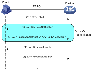
SmartOn
The SmartOn feature was developed to support the NEC 802.1X client.
As shown in Figure 11, the access device performs SmartOn authentication before 802.1X authentication. The following shows the authentication process:
1. When a SmartOn-enabled port receives an EAPOL-Start packet from an 802.1X client, it sends a unicast EAP-Request/Notification packet to the client for SmartOn authentication.
2. Upon receiving an EAP-Response/Notification from the client, the device compares the switch ID and password in the packet with the switch ID and password configured on the device.
¡ If they are the same, 802.1X authentication can continue.
¡ If they do not match, SmartOn authentication fails. The access device stops 802.1X authentication for the client.
Figure 11 802.1X authentication process with the SmartOn feature
If the user attempts to use another 802.1X client for authentication, it will fail SmartOn authentication. The access device stops 802.1X authentication for the user.
|
|
NOTE: After you install the SmartOn client software, add two values QX_ID and QX_PASSWORD to the Windows registry key [HKEY_LOCAL_MACHINE\SOFTWARE\Soliton Systems K.K.\SmartOn Client\Clients\1XGate]. Specify the switch ID and password for the QX_ID and QX_PASSWORD, respectively. The switch ID and password must be the same as the switch ID and password configured on the device. |
Configuration prerequisites
Before you configure 802.1X, complete the following tasks:
· Configure an ISP domain and AAA scheme (local or RADIUS authentication) for 802.1X users.
· If RADIUS authentication is used, create user accounts on the RADIUS server.
· If local authentication is used, create local user accounts on the access device and set the service type to lan-access.
802.1X configuration task list
Enabling 802.1X
When you enable 802.1X, follow these guidelines:
· If the PVID is a voice VLAN, the 802.1X feature cannot take effect on the port. For more information about voice VLANs, see Layer 2—LAN Switching Configuration Guide.
· Do not enable 802.1X on a port that is in a link aggregation or service loopback group.
To enable 802.1X:
|
Step |
Command |
Remarks |
|
1. Enter system view. |
system-view |
N/A |
|
2. Enable 802.1X globally. |
dot1x |
By default, 802.1X is disabled globally. |
|
3. Enter Ethernet interface view. |
interface interface-type interface-number |
N/A |
|
4. Enable 802.1X on a port. |
dot1x |
By default, 802.1X is disabled on a port. |
Enabling EAP relay or EAP termination
When configuring EAP relay or EAP termination, consider the following factors:
· Support of the RADIUS server for EAP packets.
· Authentication methods supported by the 802.1X client and the RADIUS server.
You can use both EAP termination and EAP relay in any of the following situations:
· The client is using only MD5-Challenge EAP authentication. If EAP termination is used, you must enable CHAP authentication on the access device.
· The client is an H3C iNode 802.1X client and initiates only the username and password EAP authentication. If EAP termination is used, you can enable either PAP or CHAP authentication on the access device. However, if the password is required to be transmitted in cipher text, you must use CHAP authentication on the access device.
To use EAP-TL, PEAP, or any other EAP authentication methods, you must use EAP relay. When you make your decision, see "Comparing EAP relay and EAP termination" for help.
For more information about EAP relay and EAP termination, see "802.1X authentication procedures."
To configure EAP relay or EAP termination:
|
Step |
Command |
Remarks |
|
1. Enter system view. |
system-view |
N/A |
|
2. Configure EAP relay or EAP termination. |
dot1x authentication-method { chap | eap | pap } |
By default, the access device performs EAP termination and uses CHAP to communicate with the RADIUS server. Specify the eap keyword to enable EAP relay. Specify the chap or pap keyword to enable CHAP-enabled or PAP-enabled EAP termination. |
|
|
NOTE: If EAP relay mode is used, the user-name-format command configured in RADIUS scheme view does not take effect. The access device sends the authentication data from the client to the server without any modification. |
Setting the port authorization state
The port authorization state determines whether the client is granted access to the network. You can control the authorization state of a port by using the dot1x port-control command and the following keywords:
· authorized-force—Places the port in the authorized state, enabling users on the port to access the network without authentication.
· unauthorized-force—Places the port in the unauthorized state, denying any access requests from users on the port.
· auto—Places the port initially in unauthorized state to allow only EAPOL packets to pass. After a user passes authentication, sets the port in the authorized state to allow access to the network. You can use this option in most scenarios.
To set the authorization state of a port:
|
Step |
Command |
Remarks |
|
1. Enter system view. |
system-view |
N/A |
|
2. Enter Ethernet interface view. |
interface interface-type interface-number |
N/A |
|
3. Set the port authorization state. |
dot1x port-control { authorized-force | auto | unauthorized-force } |
By default, the auto state applies. |
Specifying an access control method
|
Step |
Command |
Remarks |
|
1. Enter system view. |
system-view |
N/A |
|
2. Enter Ethernet interface view. |
interface interface-type interface-number |
N/A |
|
3. Specify an access control method. |
dot1x port-method { macbased | portbased } |
By default, MAC-based access control applies. To use both 802.1X and portal authentication on a port, you must specify MAC-based access control. For information about portal authentication, see "Configuring portal authentication." |
Setting the maximum number of concurrent 802.1X users on a port
Perform this task to prevent the system resources from being overused.
To set the maximum number of concurrent 802.1X users on a port:
|
Step |
Command |
Remarks |
|
1. Enter system view. |
system-view |
N/A |
|
2. Enter Ethernet interface view. |
interface interface-type interface-number |
N/A |
|
3. Set the maximum number of concurrent 802.1X users on a port. |
dot1x max-user max-number |
The default setting is 4294967295. |
Setting the maximum number of authentication request attempts
The access device retransmits an authentication request if it does not receive any responses to the request from the client within a period of time. To set the time, use the dot1x timer tx-period tx-period-value command or the dot1x timer supp-timeout supp-timeout-value command. The access device stops retransmitting the request if it has made the maximum number of request transmission attempts but still receives no response.
To set the maximum number of authentication request attempts:
|
Step |
Command |
Remarks |
|
1. Enter system view. |
system-view |
N/A |
|
2. Set the maximum number of attempts for sending an authentication request. |
dot1x retry retries |
The default setting is 2. |
Setting the 802.1X authentication timeout timers
The network device uses the following 802.1X authentication timeout timers:
· Client timeout timer—Starts when the access device sends an EAP-Request/MD5-Challenge packet to a client. If no response is received when this timer expires, the access device retransmits the request to the client.
· Server timeout timer—Starts when the access device sends a RADIUS Access-Request packet to the authentication server. If no response is received when this timer expires, the access device retransmits the request to the server.
In most cases, the default settings are sufficient. You can edit the timers, depending on the network conditions.
· In a low-speed network, increase the client timeout timer.
· In a network with authentication servers of different performance, adjust the server timeout timer.
To set the 802.1X authentication timeout timers:
|
Step |
Command |
Remarks |
|
1. Enter system view. |
system-view |
N/A |
|
2. Set the client timeout timer. |
dot1x timer supp-timeout supp-timeout-value |
The default is 30 seconds. |
|
3. Set the server timeout timer. |
dot1x timer server-timeout server-timeout-value |
The default is 100 seconds. |
Configuring online user handshake
The online user handshake feature checks the connectivity status of online 802.1X users. The access device sends handshake requests (EAP-Request/Identity) to online users at the interval specified by the dot1x timer handshake-period command. If the device does not receive any EAP-Response/Identity packets from an online user after it has made the maximum handshake attempts, the device sets the user to offline state. To set the maximum handshake attempts, use the dot1x retry command.
Typically, the device does not reply to 802.1X clients' EAP-Response/Identity packets with EAP-Success packets. Some 802.1X clients will go offline if they do not receive the EAP-Success packets for handshake. To avoid this problem, enable the online user handshake reply feature.
If iNode clients are deployed, you can also enable the online user handshake security feature to check authentication information in the handshake packets from clients. This feature can prevent 802.1X users who use illegal client software from bypassing iNode security check, such as dual network interface cards (NICs) detection. If a user fails the handshake security checking, the device sets the user to the offline state.
Configuration guidelines
When you configure online user handshake, follow these restrictions and guidelines:
· The SmartOn feature and the online user handshake feature are mutually exclusive. Before you enable the online user handshake feature, make sure the SmartOn feature is disabled.
· To use the online user handshake security feature, make sure the online user handshake feature is enabled.
· The online user handshake security feature takes effect only on the network where the iNode client and IMC server are used.
· If the network has 802.1X clients that cannot exchange handshake packets with the access device, disable the online user handshake feature. This operation prevents the 802.1X connections from being incorrectly torn down.
· Enable the online user handshake reply feature only if 802.1X clients will go offline without receiving EAP-Success packets from the device.
Configuration procedure
To configure the online user handshake feature:
|
Step |
Command |
Remarks |
|
1. Enter system view. |
system-view |
N/A |
|
2. (Optional.) Set the handshake timer. |
dot1x timer handshake-period handshake-period-value |
The default is 15 seconds. |
|
3. Enter Ethernet interface view. |
interface interface-type interface-number |
N/A |
|
4. Enable the online user handshake feature. |
dot1x handshake |
By default, the feature is enabled. |
|
5. (Optional.) Enable the online user handshake security feature. |
dot1x handshake secure |
By default, the feature is disabled. |
|
6. (Optional.) Enable the 802.1X online user handshake reply feature. |
dot1x handshake reply enable |
By default, the device does not reply to 802.1X clients' EAP-Response/Identity packets during the online handshake process. |
Configuring the authentication trigger feature
The authentication trigger feature enables the access device to initiate 802.1X authentication when 802.1X clients cannot initiate authentication.
This feature provides the multicast trigger and unicast trigger (see 802.1X authentication initiation in "802.1X overview").
Configuration guidelines
When you configure the authentication trigger feature, follow these guidelines:
· Enable the multicast trigger on a port when the clients attached to the port cannot send EAPOL-Start packets to initiate 802.1X authentication.
· Enable the unicast trigger on a port if only a few 802.1X clients are attached to the port and these clients cannot initiate authentication.
· To avoid duplicate authentication packets, do not enable both triggers on a port.
Configuration procedure
To configure the authentication trigger feature on a port:
|
Step |
Command |
Remarks |
|
1. Enter system view. |
system-view |
N/A |
|
2. (Optional.) Set the username request timeout timer. |
dot1x timer tx-period tx-period-value |
The default is 30 seconds. |
|
3. Enter Ethernet interface view. |
interface interface-type interface-number |
N/A |
|
4. Enable an authentication trigger. |
dot1x { multicast-trigger | unicast-trigger } |
By default, the multicast trigger is enabled, and the unicast trigger is disabled. |
Specifying a mandatory authentication domain on a port
You can place all 802.1X users in a mandatory authentication domain for authentication, authorization, and accounting on a port. No user can use an account in any other domain to access the network through the port. The implementation of a mandatory authentication domain enhances the flexibility of 802.1X access control deployment.
To specify a mandatory authentication domain for a port:
|
Step |
Command |
Remarks |
|
1. Enter system view. |
system-view |
N/A |
|
2. Enter Ethernet interface view. |
interface interface-type interface-number |
N/A |
|
3. Specify a mandatory 802.1X authentication domain on the port. |
dot1x mandatory-domain domain-name |
By default, no mandatory 802.1X authentication domain is specified. |
Setting the quiet timer
The quiet timer enables the access device to wait a period of time before it can process any authentication request from a client that has failed an 802.1X authentication.
You can edit the quiet timer, depending on the network conditions.
· In a vulnerable network, set the quiet timer to a high value.
· In a high-performance network with quick authentication response, set the quiet timer to a low value.
To set the quiet timer:
|
Step |
Command |
Remarks |
|
1. Enter system view. |
system-view |
N/A |
|
2. Enable the quiet timer. |
dot1x quiet-period |
By default, the timer is disabled. |
|
3. (Optional.) Set the quiet timer. |
dot1x timer quiet-period quiet-period-value |
The default is 60 seconds. |
Configuring 802.1X reauthentication
Overview
802.1X reauthentication tracks the connection status of online users and updates the authorization attributes assigned by the server. The attributes include the ACL and VLAN.
The following methods are available for 802.1X reauthentication:
· Manual reauthentication—Allows you to manually reauthenticate all online 802.1X users on a port.
· Periodic reauthentication—Reauthenticates online users at a user-configurable reauthentication interval.
By default, the device logs off online 802.1X users if no server is reachable for 802.1X reauthentication. The keep-online feature keeps authenticated 802.1X users online when no server is reachable for 802.1X reauthentication, either manually or periodically.
Configuration restrictions and guidelines
When you configure 802.1X reauthentication, follow these restrictions and guidelines:
· The server-assigned session timeout timer (Session-Timeout attribute) and termination action (Termination-Action attribute) together can affect periodic reauthentication. To display the server-assigned Session-Timeout and Termination-Action attributes, use the display dot1x connection command (see Security Command Reference).
¡ If the termination action is Default (logoff), periodic reauthentication on the device takes effect only when the periodic reauthentication timer is shorter than the session timeout timer.
¡ If the termination action is Radius-request, the periodic reauthentication configuration on the device does not take effect. The device reauthenticates the online 802.1X users after the session timeout timer expires.
Support for the assignment of Session-Timeout and Termination-Action attributes depends on the server model.
· You can set the periodic reauthentication timer either in system view or in interface view by using the dot1x timer reauth-period command. A change to the periodic reauthentication timer applies to online users only after the old timer expires.
The device selects a periodic reauthentication timer for 802.1X reauthentication in the following order:
a. Server-assigned reauthentication timer.
b. Port-specific reauthentication timer.
c. Global reauthentication timer.
d. Default reauthentication timer.
· The VLANs assigned to an online user before and after reauthentication can be the same or different.
Configuring 802.1X periodic reauthentication
|
Step |
Command |
Remarks |
|
1. Enter system view. |
system-view |
N/A |
|
2. (Optional.) Set the global periodic reauthentication timer. |
dot1x timer reauth-period reauth-period-value |
The default is 3600 seconds. |
|
3. Enter Ethernet interface view. |
interface interface-type interface-number |
N/A |
|
4. Enable 802.1X periodic reauthentication. |
dot1x re-authenticate |
By default, the feature is disabled. |
|
5. (Optional.) Set the periodic reauthentication timer on the port. |
dot1x timer reauth-period reauth-period-value |
By default, no periodic reauthentication timer is set on a port. The port uses the global 802.1X periodic reauthentication timer. |
Configuring 802.1X manual reauthentication
|
Step |
Command |
Remarks |
|
1. Enter system view. |
system-view |
N/A |
|
2. Enter Ethernet interface view. |
interface interface-type interface-number |
N/A |
|
3. Manually reauthenticate all online 802.1X users on the port. |
dot1x re-authenticate manual |
The device immediately reauthenticates all online 802.1X users on the port after you execute this command. |
Enabling the keep-online feature
|
Step |
Command |
Remarks |
|
1. Enter system view. |
system-view |
N/A |
|
2. Enter Ethernet interface view. |
interface interface-type interface-number |
N/A |
|
3. Enable the keep-online feature for 802.1X users. |
dot1x re-authenticate server-unreachable keep-online |
By default, this feature is disabled. The device logs off online 802.1X users if no authentication server is reachable for 802.1X reauthentication, either manually or periodically. Use the keep-online feature according to the actual network condition. In a fast-recovery network, you can use the keep-online feature to prevent 802.1X users from coming online and going offline frequently. |
Configuring an 802.1X guest VLAN
Configuration guidelines
When you configure an 802.1X guest VLAN, follow these restrictions and guidelines:
· The following matrix shows the location restrictions for the interface configured with 802.1X guest VLAN and the interface connected to the external network on an IRF 3 system:
|
Location of the interface configured with 802.1X guest VLAN |
Location restrictions of the interface connected to the external network |
|
A PEX |
The interface cannot be on an interface module of the parent fabric or on other PEXs. |
|
An interface module on the parent fabric |
The interface cannot be on PEXs. |
For more information about IRF 3, see Virtual Technologies Configuration Guide.
· You can configure only one 802.1X guest VLAN on a port. The 802.1X guest VLANs on different ports can be different.
· Assign different IDs to the voice VLAN, the port VLAN, and the 802.1X guest VLAN on a port. The assignment makes sure the port can correctly process incoming VLAN-tagged traffic.
· When you configure multiple security features on a port, follow the guidelines in Table 4.
Table 4 Relationships of the 802.1X guest VLAN and other security features
|
Feature |
Relationship description |
Reference |
|
MAC-based VLAN |
The MAC-based VLAN has higher priority than the 802.1X guest VLAN on a port that performs port-based access control. |
See Layer 2—LAN Switching Configuration Guide. |
|
Super VLAN |
You cannot specify a VLAN as both a super VLAN and an 802.1X guest VLAN. |
See Layer 2—LAN Switching Configuration Guide. |
|
802.1X Auth-Fail VLAN on a port that performs MAC-based access control |
The 802.1X Auth-Fail VLAN has higher priority than the 802.1X guest VLAN. |
See "802.1X VLAN manipulation." |
|
Port intrusion protection actions on a port that performs MAC-based access control |
The 802.1X guest VLAN feature has higher priority than the block MAC action. The 802.1X guest VLAN feature has lower priority than the shutdown port action of the port intrusion protection feature. |
See "Configuring port security." |
Configuration prerequisites
Before you configure an 802.1X guest VLAN, complete the following tasks:
· Create the VLAN to be specified as the 802.1X guest VLAN.
· If the 802.1X-enabled port performs MAC-based access control, perform the following operations for the port:
¡ Configure the port as a hybrid port.
¡ Enable MAC-based VLAN on the port. For more information about MAC-based VLANs, see Layer 2—LAN Switching Configuration Guide.
¡ Assign the port to the 802.1X guest VLAN as an untagged member.
Configuration procedure
To configure an 802.1X guest VLAN:
|
Step |
Command |
Remarks |
|
1. Enter system view. |
system-view |
N/A |
|
2. Enter Ethernet interface view. |
interface interface-type interface-number |
N/A |
|
3. Configure the 802.1X guest VLAN on the port. |
dot1x guest-vlan guest-vlan-id |
By default, no 802.1X guest VLAN exists. |
Enabling 802.1X guest VLAN assignment delay
This feature delays assigning an 802.1X-enabled port to the 802.1X guest VLAN when 802.1X authentication is triggered on the port.
This feature applies only to situations where 802.1X authentication is triggered by EAPOL-Start packets from 802.1X clients or packets from unknown MAC addresses.
To use this feature, the 802.1X-enabled port must perform MAC-based access control.
When 802.1X authentication is triggered on a port, the device performs the following operations:
1. Sends a unicast EAP-Request/Identity packet to the MAC address that triggers the authentication.
2. Retransmits the packet if no response is received within the username request timeout interval set by using the dot1x timer tx-period command.
3. Assigns the port the 802.1X guest VLAN after the maximum number of request attempts set by using the dot1x retry command is reached.
To enable 802.1X guest VLAN assignment delay on a port:
|
Step |
Command |
Remarks |
|
1. Enter system view. |
system-view |
N/A |
|
2. Enter Layer 2 Ethernet interface view. |
interface interface-type interface-number |
N/A |
|
3. Enable 802.1X guest VLAN assignment delay on the port. |
dot1x guest-vlan-delay { eapol | new-mac } |
By default, 802.1X guest VLAN assignment delay is disabled on a port. |
Configuring an 802.1X Auth-Fail VLAN
Configuration guidelines
When you configure an 802.1X Auth-Fail VLAN, follow these restrictions and guidelines:
· Assign different IDs to the voice VLAN, the port VLAN, and the 802.1X Auth-Fail VLAN on a port. The assignment makes sure the port can correctly process VLAN-tagged incoming traffic.
· You can configure only one 802.1X Auth-Fail VLAN on a port. The 802.1X Auth-Fail VLANs on different ports can be different.
· When you configure multiple security features on a port, follow the guidelines in Table 5.
Table 5 Relationships of the 802.1X Auth-Fail VLAN with other features
|
Feature |
Relationship description |
Reference |
|
Super VLAN |
You cannot specify a VLAN as both a super VLAN and an 802.1X Auth-Fail VLAN. |
See Layer 2—LAN Switching Configuration Guide. |
|
MAC authentication guest VLAN on a port that performs MAC-based access control |
The 802.1X Auth-Fail VLAN has a high priority. |
See "Configuring MAC authentication." |
|
Port intrusion protection actions on a port that performs MAC-based access control |
The 802.1X Auth-Fail VLAN feature has higher priority than the block MAC action. The 802.1X Auth-Fail VLAN feature has lower priority than the shutdown port action of the port intrusion protection feature. |
See "Configuring port security." |
Configuration prerequisites
Before you configure an 802.1X Auth-Fail VLAN, complete the following tasks:
· Create the VLAN to be specified as the 802.1X Auth-Fail VLAN.
· If the 802.1X-enabled port performs MAC-based access control, perform the following operations for the port:
¡ Configure the port as a hybrid port.
¡ Enable MAC-based VLAN on the port. For more information about MAC-based VLANs, see Layer 2—LAN Switching Configuration Guide.
¡ Assign the port to the Auth-Fail VLAN as an untagged member.
Configuration procedure
To configure an 802.1X Auth-Fail VLAN:
|
Step |
Command |
Remarks |
|
1. Enter system view. |
system-view |
N/A |
|
2. Enter Ethernet interface view. |
interface interface-type interface-number |
N/A |
|
3. Configure the 802.1X Auth-Fail VLAN on the port. |
dot1x auth-fail vlan authfail-vlan-id |
By default, no 802.1X Auth-Fail VLAN exists. |
Configuring an 802.1X critical VLAN
Typically, when a client user is assigned to the 802.1X critical VLAN on a port, the device sends an EAP-Failure packet to the client. Some 802.1X clients, such as Windows built-in 802.1X clients, cannot respond to the EAP-Request/Identity packets of the device if they have received an EAP-Failure packet. As a result, reauthentication fails for these clients when an authentication server is reachable.
To solve this problem, configure the device to send EAP-Success packets instead of EAP-Failure packets for 802.1X user assignment to the 802.1X critical VLAN. This configuration ensures that all 802.1X clients can perform reauthentication.
Configuration guidelines
When you configure an 802.1X critical VLAN, follow these restrictions and guidelines:
· Assign different IDs to the voice VLAN, the PVID, and the 802.1X critical VLAN on a port. The assignment makes sure the port can correctly process VLAN-tagged incoming traffic.
· You can configure only one 802.1X critical VLAN on a port. The 802.1X critical VLANs on different ports can be different.
· You cannot specify a VLAN as both a super VLAN and an 802.1X critical VLAN. For information about super VLANs, see Layer 2—LAN Switching Configuration Guide.
Configuration prerequisites
Before you configure an 802.1X critical VLAN, complete the following tasks:
· Create the VLAN to be specified as a critical VLAN.
· If the 802.1X-enabled port performs MAC-based access control, perform the following operations for the port:
¡ Configure the port as a hybrid port.
¡ Enable MAC-based VLAN on the port. For more information about MAC-based VLANs, see Layer 2—LAN Switching Configuration Guide.
¡ Assign the port to the 802.1X critical VLAN as an untagged member.
Configuration procedure
To configure an 802.1X critical VLAN:
|
Step |
Command |
Remarks |
|
1. Enter system view. |
system-view |
N/A |
|
2. Enter Ethernet interface view. |
interface interface-type interface-number |
N/A |
|
3. Configure the 802.1X critical VLAN on the port. |
dot1x critical vlan critical-vlan-id |
By default, no 802.1X critical VLAN exists. |
|
4. (Optional.) Send an EAP-Success packet to a client when the 802.1X client user is assigned to the 802.1X critical VLAN on the port. |
dot1x critical eapol |
By default, the device sends an EAP-Failure packet to a client when the 802.1X client user is assigned to the 802.1X critical VLAN on the port. |
Enabling the 802.1X critical voice VLAN
Configuration restrictions and guidelines
The feature does not take effect if the voice user has been in the 802.1X Auth-Fail VLAN.
Configuration prerequisites
Before you enable the 802.1X critical voice VLAN on a port, complete the following tasks:
· Enable LLDP both globally and on the port.
The device uses LLDP to identify voice users. For information about LLDP, see Layer 2—LAN Switching Configuration Guide.
· Enable voice VLAN on the port.
For information about voice VLANs, see Layer 2—LAN Switching Configuration Guide.
Configuration procedure
To enable the 802.1X critical voice VLAN feature on a port:
|
Step |
Command |
Remarks |
|
1. Enter system view. |
system-view |
N/A |
|
2. Enter Ethernet interface view. |
interface interface-type interface-number |
N/A |
|
3. Enable the 802.1X critical voice VLAN feature on a port. |
dot1x critical-voice-vlan |
By default, the 802.1X critical voice VLAN feature is disabled on a port. |
Specifying supported domain name delimiters
By default, the access device supports the at sign (@) as the delimiter. You can also configure the access device to accommodate 802.1X users who use other domain name delimiters. The configurable delimiters include the at sign (@), backslash (\), dot (.), and forward slash (/). Usernames that include domain names can use the format of username@domain-name, domain-name\username, username.domain-name, or username/domain-name.
If an 802.1X username string contains multiple configured delimiters, the rightmost delimiter is the domain name delimiter. For example, if you configure the backslash (\), dot (.), and forward slash (/) as delimiters, the domain name delimiter for the username string 121.123/22\@abc is the backslash (\). The username is @abc and the domain name is 121.123/22.
If a username string contains none of the delimiters, the access device authenticates the user in the mandatory or default ISP domain.
To specify a set of domain name delimiters:
|
Step |
Command |
Remarks |
|
1. Enter system view. |
system-view |
N/A |
|
2. Specify a set of domain name delimiters for 802.1X users. |
dot1x domain-delimiter string |
By default, only the at sign (@) delimiter is supported. |
|
|
NOTE: If you configure the access device to send usernames with domain names to the RADIUS server, make sure the domain delimiter can be recognized by the RADIUS server. For username format configuration, see the user-name-format command in Security Command Reference. |
Enabling 802.1X user IP freezing
This feature works with the IP source guard feature. 802.1X-based IP source guard requires that 802.1X clients support sending user IP addresses to the access device. The device uses information such as user MAC addresses and IP addresses obtained through 802.1X to generate IPSG bindings to filter out IPv4 packets from unauthenticated 802.1X users. For information about IP source guard, see "Configuring IP source guard."
This feature prevents any authenticated 802.1X users on a port from changing their IP addresses. After you enable this feature, the port does not update the IP addresses in dynamic IPSG bindings for 802.1X users. If an 802.1X user uses an IP address different from the IP address in its IPSG binding entry, the port denies the user access.
To enable 802.1X user IP freezing:
|
Step |
Command |
Remarks |
|
1. Enter system view. |
system-view |
N/A |
|
2. Enter Layer 2 Ethernet interface view. |
interface interface-type interface-number |
N/A |
|
3. Enable 802.1X user IP freezing. |
dot1x user-ip freeze |
By default, 802.1X user IP freezing is disabled. |
Sending 802.1X protocol packets out of a port without VLAN tags
This feature enables the device to send 802.1X protocol packets out of an 802.1X-enabled port without VLAN tags. It prevents terminal devices connected to the port from failing 802.1X authentication because they cannot identify VLAN tags.
This feature is supported only on Ethernet ports whose link type is hybrid or trunk.
To enable the device to send 802.1X protocol packets out of a port without VLAN tags:
|
Step |
Command |
Remarks |
|
1. Enter system view. |
system-view |
N/A |
|
2. Enter Layer 2 Ethernet interface view. |
interface interface-type interface-number |
N/A |
|
3. Enable the device to send 802.1X protocol packets out of the port without VLAN tags. |
dot1x eapol untag |
By default, the device can send 802.1X EAPOL packets out of a port with VLAN tags. |
Setting the maximum number of 802.1X authentication attempts for MAC authenticated users
When a port uses both 802.1X authentication and MAC authentication, the device accepts 802.1X authentication requests from MAC authenticated users. If a MAC authenticated user passes 802.1X authentication, the user will come online as an 802.1X user. If the user fails 802.1X authentication, the user continues to make 802.1X authentication attempts depending on client configuration.
Perform this task to limit the number of 802.1X authentication attempts made by a MAC authenticated user.
To set the maximum number of 802.1X authentication attempts for MAC authenticated users on a port:
|
Step |
Command |
Remarks |
|
1. Enter system view. |
system-view |
N/A |
|
2. Enter Layer 2 Ethernet interface view. |
interface interface-type interface-number |
N/A |
|
3. Set the maximum number of 802.1X authentication attempts for MAC authenticated users on the port. |
dot1x after-mac-auth max-attempt max-attempts |
By default, the number of 802.1X authentication attempts for MAC authenticated users is not limited on a port. |
Configuring the EAD assistant feature
When you configure the EAD assistant feature, follow these restrictions and guidelines:
· You must disable MAC authentication and port security globally before you enable the EAD assistant feature.
· To make the EAD assistant feature take effect on an 802.1X-enabled port, you must set the port authorization mode to auto.
· When global MAC authentication or port security is enabled, the free IP does not take effect.
· If you use free IP, guest VLAN, and Auth-Fail VLAN features together, make sure the free IP segments are in both guest VLAN and Auth-Fail VLAN.
· To allow a user to obtain a dynamic IP address before it passes 802.1X authentication, make sure the DHCP server is on the free IP segment.
· The server that provides the redirect URL must be on the free IP accessible to unauthenticated users.
· To avoid using up ACL resources when a large number of EAD users exist, you can shorten the EAD rule timer.
To configure the EAD assistant feature:
|
Step |
Command |
Remarks |
|
1. Enter system view. |
system-view |
N/A |
|
2. Enable the EAD assistant feature. |
dot1x ead-assistant enable |
By default, this feature is disabled. |
|
3. Configure a free IP. |
dot1x ead-assistant free-ip ip-address { mask-length | mask-address } |
By default, no free IPs exist. |
|
4. (Optional.) Configure the redirect URL. |
dot1x ead-assistant url url-string |
By default, no redirect URL exists. Configure the redirect URL if users will use Web browsers to access the network. |
|
5. (Optional.) Set the EAD rule timer. |
dot1x timer ead-timeout ead-timeout-value |
The default setting is 30 minutes. |
Configuring 802.1X SmartOn
The SmartOn feature is mutually exclusive with the 802.1X online user handshake feature.
When the device sends a unicast EAP-Request/Notification packet to the client, it starts the SmartOn client timeout timer (set by using the dot1x smarton timer supp-timeout command).
· If the device does not receive any EAP-Response/Notification packets from the client within the timeout timer, it retransmits the EAP-Request/Notification packet to the client. After the device has made the maximum retransmission attempts but received no response, it stops the 802.1X authentication process for the client.
· If the device receives an EAP-Response/Notification packet within the timer or before the maximum retransmission attempts have been made, it starts the SmartOn authentication. If the SmartOn switch ID and the MD5 digest of the SmartOn password in the packet match those on the device, 802.1X authentication continues for the client. Otherwise, the device denies the client's 802.1X authentication request.
To configure 802.1X SmartOn:
|
Command |
Remarks |
|
|
1. Enter system view. |
system-view |
N/A |
|
2. Enter Ethernet interface view. |
interface interface-type interface-number |
N/A |
|
3. Enable the SmartOn feature on the port. |
dot1x smarton |
By default, this feature is disabled. |
|
4. Return to system view. |
quit |
N/A |
|
5. Configure the SmartOn switch ID. |
dot1x smarton switchid switch-string |
By default, no SmartOn switch ID exists. |
|
6. Set the SmartOn password. |
dot1x smarton password { cipher | simple } string |
By default, no SmartOn password exists. |
|
7. (Optional.) Set the SmartOn client timeout timer. |
dot1x smarton timer supp-timeout supp-timeout-value |
The default timer is 30 seconds. |
|
8. (Optional.) Set the maximum attempts for retransmitting an EAP-Request/Notification packet to a client. |
dot1x smarton retry retries |
By default, the device allows a maximum of 3 attempts for retransmitting an EAP-Request/Notification packet to a client. |
Displaying and maintaining 802.1X
Execute display commands in any view and reset commands in user view.
|
Task |
Command |
|
Display 802.1X session information, statistics, or configuration information of specified or all ports. |
display dot1x [ sessions | statistics ] [ interface interface-type interface-number ] |
|
(In standalone mode.) Display online 802.1X user information. |
display dot1x connection [ interface interface-type interface-number | slot slot-number | user-mac mac-address | user-name name-string ] |
|
(In IRF mode.) Display online 802.1X user information. |
display dot1x connection [ chassis chassis-number slot slot-number | interface interface-type interface-number | user-mac mac-address | user-name name-string ] |
|
Clear 802.1X statistics. |
reset dot1x statistics [ interface interface-type interface-number ] |
|
Remove users from the 802.1X guest VLAN on a port. |
reset dot1x guest-vlan interface interface-type interface-number [ mac-address mac-address ] |
802.1X authentication configuration examples
Basic 802.1X authentication configuration example
Network requirements
As shown in Figure 12, the access device performs 802.1X authentication for users who connect to GigabitEthernet 1/0/1. Implement MAC-based access control on the port, so the logoff of one user does not affect other online 802.1X users.
Use RADIUS servers to perform authentication, authorization, and accounting for the 802.1X users. If RADIUS authentication fails, perform local authentication on the access device.
Configure the RADIUS server at 10.1.1.1/24 as the primary authentication and accounting server, and the RADIUS server at 10.1.1.2/24 as the secondary authentication and accounting server. Assign all users to the ISP domain bbb.
Set the shared key to name for packets between the access device and the authentication server. Set the shared key to money for packets between the access device and the accounting server.
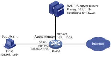
Configuration procedure
1. Configure the 802.1X client. If H3C iNode is used, do not select the Carry version info option in the client configuration. (Details not shown.)
2. Configure the RADIUS servers and add user accounts for the 802.1X users. (Details not shown.)
For information about the RADIUS commands used on the access device in this example, see Security Command Reference.
3. Assign an IP address for each interface on the access device. (Details not shown.)
4. Configure user accounts for the 802.1X users on the access device:
# Add a local network access user with username localuser and password localpass in plaintext. (Make sure the username and password are the same as those configured on the RADIUS servers.)
<Device> system-view
[Device] local-user localuser class network
[Device-luser-network-localuser] password simple localpass
# Set the service type to lan-access.
[Device-luser-network-localuser] service-type lan-access
[Device-luser-network-localuser] quit
5. Configure a RADIUS scheme:
# Create a RADIUS scheme named radius1 and enter RADIUS scheme view.
[Device] radius scheme radius1
# Specify the IP addresses of the primary authentication and accounting RADIUS servers.
[Device-radius-radius1] primary authentication 10.1.1.1
[Device-radius-radius1] primary accounting 10.1.1.1
# Configure the IP addresses of the secondary authentication and accounting RADIUS servers.
[Device-radius-radius1] secondary authentication 10.1.1.2
[Device-radius-radius1] secondary accounting 10.1.1.2
# Specify the shared key between the access device and the authentication server.
[Device-radius-radius1] key authentication simple name
# Specify the shared key between the access device and the accounting server.
[Device-radius-radius1] key accounting simple money
# Exclude the ISP domain names from the usernames sent to the RADIUS servers.
[Device-radius-radius1] user-name-format without-domain
[Device-radius-radius1] quit
|
|
NOTE: The access device must use the same username format as the RADIUS server. If the RADIUS server includes the ISP domain name in the username, so must the access device. |
6. Configure the ISP domain:
# Create an ISP domain named bbb and enter ISP domain view.
[Device] domain bbb
# Apply RADIUS scheme radius1 to the ISP domain, and specify local authentication as the secondary authentication method.
[Device-isp-bbb] authentication lan-access radius-scheme radius1 local
[Device-isp-bbb] authorization lan-access radius-scheme radius1 local
[Device-isp-bbb] accounting lan-access radius-scheme radius1 local
[Device-isp-bbb] quit
7. Configure 802.1X:
# Enable 802.1X on GigabitEthernet 1/0/1.
[Device] interface gigabitethernet 1/0/1
[Device-GigabitEthernet1/0/1] dot1x
# Enable MAC-based access control on the port. By default, the port uses MAC-based access control.
[Device-GigabitEthernet1/0/1] dot1x port-method macbased
# Specify ISP domain bbb as the mandatory domain.
[Device-GigabitEthernet1/0/1] dot1x mandatory-domain bbb
[Device-GigabitEthernet1/0/1] quit
# Enable 802.1X globally.
[Device] dot1x
Verifying the configuration
# Verify the 802.1X configuration on GigabitEthernet 1/0/1.
[Device] display dot1x interface gigabitethernet 1/0/1
# Display the user connection information after an 802.1X user passes authentication.
[Device] display dot1x connection
802.1X guest VLAN and authorization VLAN configuration example
Network requirements
As shown in Figure 13, use RADIUS servers to perform authentication, authorization, and accounting for 802.1X users who connect to GigabitEthernet 1/0/2. Implement port-based access control on the port.
Configure VLAN 10 as the 802.1X guest VLAN on GigabitEthernet 1/0/2. The host and the update server are both in VLAN 10, and the host can access the update server and download the 802.1X client software.
After the host passes 802.1X authentication, the access device assigns the host to VLAN 5 where GigabitEthernet 1/0/3 is. The host can access the Internet.
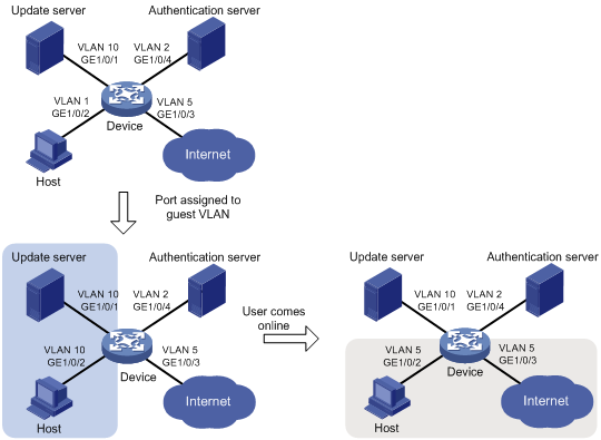
Configuration procedure
2. Configure the RADIUS server to provide authentication, authorization, and accounting services. Configure user accounts and authorization VLAN (VLAN 5 in this example) for the users. (Details not shown.)
3. Create VLANs, and assign ports to the VLANs on the access device.
<Device> system-view
[Device] vlan 1
[Device-vlan1] port gigabitethernet 1/0/2
[Device-vlan1] quit
[Device] vlan 10
[Device-vlan10] port gigabitethernet 1/0/1
[Device-vlan10] quit
[Device] vlan 2
[Device-vlan2] port gigabitethernet 1/0/4
[Device-vlan2] quit
[Device] vlan 5
[Device-vlan5] port gigabitethernet 1/0/3
[Device-vlan5] quit
4. Configure a RADIUS scheme on the access device:
# Create RADIUS scheme 2000 and enter RADIUS scheme view.
[Device] radius scheme 2000
# Specify the server at 10.11.1.1 as the primary authentication server, and set the authentication port to 1812.
[Device-radius-2000] primary authentication 10.11.1.1 1812
# Specify the server at 10.11.1.1 as the primary accounting server, and set the accounting port to 1813.
[Device-radius-2000] primary accounting 10.11.1.1 1813
# Set the shared key to abc in plain text for secure communication between the authentication server and the device.
[Device-radius-2000] key authentication simple abc
# Set the shared key to abc in plain text for secure communication between the accounting server and the device.
[Device-radius-2000] key accounting simple abc
# Exclude the ISP domain names from the usernames sent to the RADIUS server.
[Device-radius-2000] user-name-format without-domain
[Device-radius-2000] quit
5. Configure an ISP domain:
# Create ISP domain bbb and enter ISP domain view.
[Device] domain bbb
# Apply RADIUS scheme 2000 to the ISP domain for authentication, authorization, and accounting.
[Device-isp-bbb] authentication lan-access radius-scheme 2000
[Device-isp-bbb] authorization lan-access radius-scheme 2000
[Device-isp-bbb] accounting lan-access radius-scheme 2000
[Device-isp-bbb] quit
6. Configure 802.1X on the access device:
# Enable 802.1X on GigabitEthernet 1/0/2.
[Device] interface gigabitethernet 1/0/2
[Device-GigabitEthernet1/0/2] dot1x
# Implement port-based access control on the port.
[Device-GigabitEthernet1/0/2] dot1x port-method portbased
# Set the port authorization mode to auto. By default, the port uses the auto mode.
[Device-GigabitEthernet1/0/2] dot1x port-control auto
# Specify VLAN 10 as the 802.1X guest VLAN on GigabitEthernet 1/0/2.
[Device-GigabitEthernet1/0/2] dot1x guest-vlan 10
[Device-GigabitEthernet1/0/2] quit
# Enable 802.1X globally.
[Device] dot1x
Verifying the configuration
# Verify the 802.1X guest VLAN configuration on GigabitEthernet 1/0/2.
[Device] display dot1x interface gigabitethernet 1/0/2
# Verify that GigabitEthernet 1/0/2 is assigned to VLAN 10 before any user passes authentication on the port.
[Device] display vlan 10
# After a user passes authentication, display information on GigabitEthernet 1/0/2. Verify that GigabitEthernet 1/0/2 is assigned to VLAN 5.
[Device] display interface gigabitethernet 1/0/2
802.1X with ACL assignment configuration example
Network requirements
As shown in Figure 14, the host that connects to GigabitEthernet 1/0/1 must pass 802.1X authentication to access the Internet.
Perform 802.1X authentication on GigabitEthernet 1/0/1. Use the RADIUS server at 10.1.1.1 as the authentication and authorization server, and the RADIUS server at 10.1.1.2 as the accounting server.
Configure ACL assignment on GigabitEthernet 1/0/1 to deny access of 802.1X users to the FTP server from 8:00 to 18:00 on weekdays.
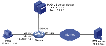
Configuration procedure
1. Configure the 802.1X client. Make sure the client is able to update its IP address after the access port is assigned to the 802.1X guest VLAN or an authorization VLAN. (Details not shown.)
2. Configure the RADIUS servers to provide authentication, authorization, and accounting services. Add user accounts and specify the ACL (ACL 3000 in this example) for the users. (Details not shown.)
3. Assign an IP address to each interface, as shown in Figure 14. (Details not shown.)
4. Configure a RADIUS scheme:
# Create RADIUS scheme 2000 and enter RADIUS scheme view.
<Device> system-view
[Device] radius scheme 2000
# Specify the server at 10.1.1.1 as the primary authentication server, and set the authentication port to 1812.
[Device-radius-2000] primary authentication 10.1.1.1 1812
# Specify the server at 10.1.1.2 as the primary accounting server, and set the accounting port to 1813.
[Device-radius-2000] primary accounting 10.1.1.2 1813
# Set the shared key to abc in plain text for secure communication between the authentication server and the device.
[Device-radius-2000] key authentication simple abc
# Set the shared key to abc in plain text for secure communication between the accounting server and the device.
[Device-radius-2000] key accounting simple abc
# Exclude the ISP domain names from the usernames sent to the RADIUS server.
[Device-radius-2000] user-name-format without-domain
[Device-radius-2000] quit
5. Configure an ISP domain:
# Create ISP domain bbb and enter ISP domain view.
[Device] domain bbb
# Apply RADIUS scheme 2000 to the ISP domain for authentication, authorization, and accounting.
[Device-isp-bbb] authentication lan-access radius-scheme 2000
[Device-isp-bbb] authorization lan-access radius-scheme 2000
[Device-isp-bbb] accounting lan-access radius-scheme 2000
[Device-isp-bbb] quit
6. Configure a time range named ftp from 8:00 to 18:00 on weekdays.
[Device] time-range ftp 8:00 to 18:00 working-day
7. Configure ACL 3000 to deny packets destined for the FTP server at 10.0.0.1 during the specified time range.
[Device] acl advanced 3000
[Device-acl-ipv4-adv-3000] rule 0 deny ip destination 10.0.0.1 0 time-range ftp
[Device-acl-ipv4-adv-3000] quit
8. Configure 802.1X:
# Enable 802.1X on GigabitEthernet 1/0/1.
[Device] interface gigabitethernet 1/0/1
[Device-GigabitEthernet1/0/1] dot1x
[Device-GigabitEthernet1/0/1] quit
# Enable 802.1X globally.
[Device] dot1x
Verifying the configuration
# Use the user account to pass authentication. (Details not shown.)
# Verify that the user cannot ping the FTP server at any time from 8:00 to 18:00 on any weekday.
C:\>ping 10.0.0.1
Pinging 10.0.0.1 with 32 bytes of data:
Request timed out.
Request timed out.
Request timed out.
Request timed out.
Ping statistics for 10.0.0.1:
Packets: Sent = 4, Received = 0, Lost = 4 (100% loss),
The output shows that ACL 3000 is active on the user, and the user cannot access the FTP server.
802.1X with EAD assistant configuration example (with DHCP relay agent)
Network requirements
As shown in Figure 15:
· The intranet 192.168.1.0/24 is attached to GigabitEthernet 1/0/1 of the access device.
· The hosts use DHCP to obtain IP addresses.
· A DHCP server and a Web server are deployed on the 192.168.2.0/24 subnet for users to obtain IP addresses and download client software.
Deploy an EAD solution for the intranet to meet the following requirements:
· Allow unauthenticated users and users who have failed 802.1X authentication to access 192.168.2.0/24. The users can obtain IP addresses and download software.
· If these users use a Web browser to access a network other than 192.168.2.0/24, redirect them to the Web server for 802.1X client downloading.
· Allow authenticated 802.1X users to access the network.
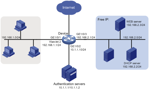
Configuration procedure
1. Make sure the DHCP server, the Web server, and the authentication servers have been configured correctly. (Details not shown.)
2. Configure an IP address for each interface. (Details not shown.)
3. Configure DHCP relay:
# Enable DHCP.
<Device> system-view
[Device] dhcp enable
# Enable the DHCP relay agent on VLAN-interface 2.
[Device] interface vlan-interface 2
[Device-Vlan-interface2] dhcp select relay
# Specify the DHCP server 192.168.2.2 on the relay agent interface VLAN-interface 2.
[Device-Vlan-interface2] dhcp relay server-address 192.168.2.2
[Device-Vlan-interface2] quit
4. Configure a RADIUS scheme:
# Create RADIUS scheme 2000 and enter RADIUS scheme view.
[Device] radius scheme 2000
# Specify the server at 10.1.1.1 as the primary authentication server, and set the authentication port to 1812.
[Device-radius-2000] primary authentication 10.1.1.1 1812
# Specify the server at 10.1.1.2 as the primary accounting server, and set the accounting port to 1813.
[Device-radius-2000] primary accounting 10.1.1.2 1813
# Set the shared key to abc in plain text for secure communication between the authentication server and the device.
[Device-radius-2000] key authentication simple abc
# Set the shared key to abc in plain text for secure communication between the accounting server and the device.
[Device-radius-2000] key accounting simple abc
# Exclude the ISP domain names from the usernames sent to the RADIUS server.
[Device-radius-2000] user-name-format without-domain
[Device-radius-2000] quit
5. Configure an ISP domain:
# Create ISP domain bbb and enter ISP domain view.
[Device] domain bbb
# Apply RADIUS scheme 2000 to the ISP domain for authentication, authorization, and accounting.
[Device-isp-bbb] authentication lan-access radius-scheme 2000
[Device-isp-bbb] authorization lan-access radius-scheme 2000
[Device-isp-bbb] accounting lan-access radius-scheme 2000
[Device-isp-bbb] quit
6. Configure 802.1X:
# Configure the free IP.
[Device] dot1x ead-assistant free-ip 192.168.2.0 24
# Configure the redirect URL for client software download.
[Device] dot1x ead-assistant url http://192.168.2.3
# Enable the EAD assistant feature.
[Device] dot1x ead-assistant enable
# Enable 802.1X on GigabitEthernet 1/0/1.
[Device] interface gigabitethernet 1/0/1
[Device-GigabitEthernet1/0/1] dot1x
[Device-GigabitEthernet1/0/1] quit
# Enable 802.1X globally.
[Device] dot1x
Verifying the configuration
# Verify the 802.1X configuration.
[Device] display dot1x
# Verify that you can ping an IP address on the free IP subnet from a host.
C:\>ping 192.168.2.3
Pinging 192.168.2.3 with 32 bytes of data:
Reply from 192.168.2.3: bytes=32 time<1ms TTL=128
Reply from 192.168.2.3: bytes=32 time<1ms TTL=128
Reply from 192.168.2.3: bytes=32 time<1ms TTL=128
Reply from 192.168.2.3: bytes=32 time<1ms TTL=128
Ping statistics for 192.168.2.3:
Packets: Sent = 4, Received = 4, Lost = 0 (0% loss),
Approximate round trip times in milli-seconds:
Minimum = 0ms, Maximum = 0ms, Average = 0ms
The output shows that you can access the free IP subnet before passing 802.1X authentication.
# Verify that you are redirected to the Web server when you enter in your Web browser an IP address not on the free IP. (Details not shown.)
802.1X with EAD assistant configuration example (with DHCP server)
Network requirements
As shown in Figure 16:
· The intranet 192.168.1.0/24 is attached to GigabitEthernet 1/0/1 of the access device.
· The hosts use DHCP to obtain IP addresses.
· A Web server is deployed on the 192.168.2.0/24 subnet for users to download client software.
Deploy an EAD solution for the intranet to meet the following requirements:
· Allow unauthenticated users and users who have failed 802.1X authentication to access 192.168.2.0/24. The users can download software.
· If these users use a Web browser to access a network other than 192.168.2.0/24, redirect them to the Web server for 802.1X client downloading.
· Allow authenticated 802.1X users to access the network.
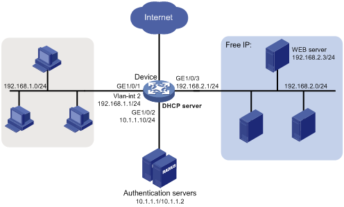
Configuration procedure
1. Make sure the Web server and the authentication servers have been configured correctly. (Details not shown.)
2. Configure an IP address for each interface. (Details not shown.)
3. Configure the DHCP server:
# Enable DHCP.
<Device> system-view
[Device] dhcp enable
# Enable the DHCP server on VLAN-interface 2.
[Device] interface vlan-interface 2
[Device-Vlan-interface2] dhcp select server
[Device-Vlan-interface2] quit
# Create DHCP address pool 0.
[Device] dhcp server ip-pool 0
# Specify subnet 192.168.1.0/24 in DHCP address pool 0.
[Device-dhcp-pool-0] network 192.168.1.0 mask 255.255.255.0
# Specify the gateway address 192.168.1.1 in DHCP address pool 0.
[Device-dhcp-pool-0] gateway-list 192.168.1.1
[Device-dhcp-pool-0] quit
4. Configure a RADIUS scheme:
# Create RADIUS scheme 2000 and enter RADIUS scheme view.
[Device] radius scheme 2000
# Specify the server at 10.1.1.1 as the primary authentication server, and set the authentication port to 1812.
[Device-radius-2000] primary authentication 10.1.1.1 1812
# Specify the server at 10.1.1.2 as the primary accounting server, and set the accounting port to 1813.
[Device-radius-2000] primary accounting 10.1.1.2 1813
# Set the shared key to abc in plain text for secure communication between the authentication server and the device.
[Device-radius-2000] key authentication simple abc
# Set the shared key to abc in plain text for secure communication between the accounting server and the device.
[Device-radius-2000] key accounting simple abc
# Exclude the ISP domain names from the usernames sent to the RADIUS server.
[Device-radius-2000] user-name-format without-domain
[Device-radius-2000] quit
5. Configure an ISP domain:
# Create ISP domain bbb and enter ISP domain view.
[Device] domain bbb
# Apply RADIUS scheme 2000 to the ISP domain for authentication, authorization, and accounting.
[Device-isp-bbb] authentication lan-access radius-scheme 2000
[Device-isp-bbb] authorization lan-access radius-scheme 2000
[Device-isp-bbb] accounting lan-access radius-scheme 2000
[Device-isp-bbb] quit
6. Configure 802.1X:
# Configure the free IP.
[Device] dot1x ead-assistant free-ip 192.168.2.0 24
# Configure the redirect URL for client software download.
[Device] dot1x ead-assistant url http://192.168.2.3
# Enable the EAD assistant feature.
[Device] dot1x ead-assistant enable
# Enable 802.1X on GigabitEthernet 1/0/1.
[Device] interface gigabitethernet 1/0/1
[Device-GigabitEthernet1/0/1] dot1x
[Device-GigabitEthernet1/0/1] quit
# Enable 802.1X globally.
[Device] dot1x
Verifying the configuration
# Verify the 802.1X configuration.
[Device] display dot1x
# Verify that you can ping an IP address on the free IP subnet from a host.
C:\>ping 192.168.2.3
Pinging 192.168.2.3 with 32 bytes of data:
Reply from 192.168.2.3: bytes=32 time<1ms TTL=128
Reply from 192.168.2.3: bytes=32 time<1ms TTL=128
Reply from 192.168.2.3: bytes=32 time<1ms TTL=128
Reply from 192.168.2.3: bytes=32 time<1ms TTL=128
Ping statistics for 192.168.2.3:
Packets: Sent = 4, Received = 4, Lost = 0 (0% loss),
Approximate round trip times in milli-seconds:
Minimum = 0ms, Maximum = 0ms, Average = 0ms
The output shows that you can access the free IP subnet before passing 802.1X authentication.
# Verify that you are redirected to the Web server when you enter in your Web browser an IP address not on the free IP. (Details not shown.)
802.1X SmartOn configuration example
Network requirements
As shown in Figure 17, configure the SmartOn feature on GigabitEthernet 1/0/1 so that the host must pass SmartOn authentication before 802.1X authentication.
Set the SmartOn password to 1234 in plain text and switch ID to XYZ. Set the SmartOn client timeout timer to 40 seconds.
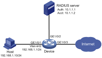
Configuration procedure
1. Configure a RADIUS scheme:
# Create RADIUS scheme 2000 and enter RADIUS scheme view.
<Device> system-view
[Device] radius scheme 2000
# Specify the server at 10.1.1.1 as the primary authentication server, and set the authentication port to 1812.
[Device-radius-2000] primary authentication 10.1.1.1 1812
# Specify the server at 10.1.1.2 as the primary accounting server, and set the accounting port to 1813.
[Device-radius-2000] primary accounting 10.1.1.2 1813
# Set the shared key to abc in plain text for secure communication between the authentication server and the device.
[Device-radius-2000] key authentication simple abc
# Set the shared key to abc in plain text for secure communication between the accounting server and the device.
[Device-radius-2000] key accounting simple abc
# Exclude the ISP domain names from the usernames sent to the RADIUS server.
[Device-radius-2000] user-name-format without-domain
[Device-radius-2000] quit
2. Configure an ISP domain:
# Create ISP domain bbb and enter ISP domain view.
[Device] domain bbb
# Apply RADIUS scheme 2000 to the ISP domain for authentication, authorization, and accounting.
[Device-isp-bbb] authentication lan-access radius-scheme 2000
[Device-isp-bbb] authorization lan-access radius-scheme 2000
[Device-isp-bbb] accounting lan-access radius-scheme 2000
[Device-isp-bbb] quit
3. Configure 802.1X and SmartOn:
# Enable 802.1X on GigabitEthernet 1/0/1.
[Device] interface gigabitethernet 1/0/1
[Device-GigabitEthernet1/0/1] dot1x
# Enable SmartOn on GigabitEthernet 1/0/1.
[Device-GigabitEthernet1/0/1] dot1x smarton
[Device-GigabitEthernet1/0/1] quit
# Set the SmartOn password to 1234 in plain text and the switch ID to XYZ.
[Device] dot1x smarton password simple 1234
[Device] dot1x smarton switchid XYZ
# Set the SmartOn client timeout timer to 40 seconds.
[Device] smarton timer supp-timeout 40
# Enable 802.1X globally.
[Device] dot1x
Troubleshooting 802.1X
EAD assistant URL redirection failure
Symptom
Unauthenticated users are not redirected to the specified redirect URL after they enter external website addresses in their Web browsers.
Analysis
Redirection will not happen for one of the following reasons:
· The address is in the string format. The operating system of the host regards the string as a website name and tries to resolve the string. If the resolution fails, the operating system sends an ARP request, but the target address is not in the dotted decimal notation. The redirection feature does redirect this kind of ARP request.
· The address is within a free IP segment. No redirection will take place, even if no host is present with the address.
· The redirect URL is not in a free IP segment.
· No server is using the redirect URL, or the server with the URL does not provide Web services.
Solution
To resolve the problem:
1. Enter a dotted decimal IP address that is not in any free IP segments.
2. Verify that the access device and the server are configured correctly.
3. If the problem persists, contact H3C Support.