| Title | Size | Downloads |
|---|---|---|
| H3C SR6600_SR6600-X Routers Interface Module Guide-6W106-Text.pdf | 1.54 MB |
- Table of Contents
- Related Documents
-
| Title | Size | Download |
|---|---|---|
| 01-Text | 1.54 MB |
Contents
HIM-4GBE (RT-HIM-4GBE-WAN-H3)/HIM-8GBE (RT-HIM-8GBE-WAN-H3)
HIM-4GBP (RT-HIM-4GBP-H3)/HIM-8GBP (RT-HIM-8GBP-H3)
HIM-CL1P (RT-HIM-1CPOS/STM1-H3)/HIM-CL2P (RT-HIM-2CPOS/STM1-H3)
HIM-CLS1P (RT-HIM-CLS1P-H3)/HIM-CLS2P (RT-HIM-CLS2P-H3)
HIM-MSP2P (RT-HIM-MSP2P-H3)/HIM-MSP4P (RT-HIM-MSP4P-H3)
HIM-PS1P (RT-HIM-1POS/STM16-H3)
HIM-AL1P (RT-HIM-AL1P-H3)/HIM-AL2P (RT-HIM-AL2P-H3)
MIM-8E1(75)(RT-MIM-8E1(75)-H3)/MIM-8E1(75)-F(RT-MIM-8E1(75)-F-H3)
MIM-8T1/MIM-8T1-F RT-MIM-8T1-H3)/MIM-8T1-F (RT-MIM-8T1-F-H3)
MIM-2SAE (RT-MIM-2SAE-H3)/MIM-4SAE (RT-MIM-4SAE-H3)/MIM-8SAE (RT-MIM-8SAE-H3)
Connecting an Ethernet interface cable
Connecting an optical interface cable
Connecting an E1 interface cable
Connecting a T1 interface cable
Connecting a CE3/CT3 interface cable
Connecting a serial interface cable
Compatibility matrixes on Comware V5
LPU and router compatibility matrix
LPU and MPU compatibility matrix
MPU and router compatibility matrix
Compatibility matrixes on Comware V7
LPU and router compatibility matrix
LPU and MPU compatibility matrix
MPU and router compatibility matrix
Interface module and FIP compatibility matrix
Interface module&SAP and transceiver module compatibility matrix
The SR6600/SR6600-X router supports hot swapping of interface modules.
|
|
NOTE: The LPU, MPU, and router compatibility matrixes vary by Comware system. For more information, see "Compatibility matrixes." |
HIMs
HIM-8FE (RT-HIM-8FE-H3)
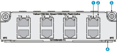
The HIM-8FE is a 10Base-T/100Base-TX Fast Ethernet (FE) interface module used by a router to communicate with a LAN. It provides eight RJ-45 ports, each of which supports the Layer 3 routing function and has a bi-color status LED.
The HIM-8FE has the following features:
· The transmission distance can be up to 100 meters (328.08 ft) if a category-5 twisted pair cable is used.
· The interfaces support 10/100 Mbps auto-sensing.
· The interfaces typically operate in full duplex mode and can also operate in half duplex mode.
Front panel
|
(1) FE port |
(2) FE port status LED |
|
(3) Captive screw |
(4) Ejector lever |
LEDs
Table 1 LED description
|
LED status |
Description |
|
Off |
No link is present or the cable is faulty. |
|
Steady yellow |
A 10 Mbps link is present. |
|
Flashing yellow |
Data is being received or transmitted at 10 Mbps. |
|
Steady green |
A 100 Mbps link is present. |
|
Flashing green |
Data is being received or transmitted at 100 Mbps. |
Interface specifications
Table 2 Interface specifications
|
Item |
Specification |
|
Connector type |
RJ-45 |
|
Number of interfaces |
8 |
|
Interface standards |
802.3, 802.3u |
|
Interface type |
Auto MDI/MDI-X |
|
Cable type |
Straight-through/crossover cable |
|
Transmission distance |
100 m (328.08 ft) |
|
Interface speed and duplex mode |
· 10/100 Mbps auto-sensing · Full duplex/half duplex |
|
|
NOTE: The medium dependent interface (MDI) standard is typically used on the Ethernet interface of network adapters; the medium dependent interface crossover (MDI-X) standard is typically used on hubs or LAN switches. |
Interface cables
The HIM-8FE uses a category-5 straight-through cable or crossover Ethernet cable. For the appearance and connection of a HIM-8FE interface cable, see "Connecting an Ethernet interface cable."
HIM-4GBE (RT-HIM-4GBE-WAN-H3)/HIM-8GBE (RT-HIM-8GBE-WAN-H3)
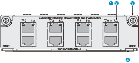
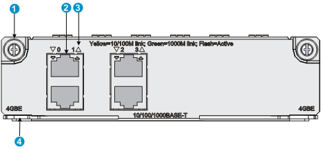
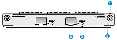
The HIM-4GBE and HIM-8GBE are 10Base-T/100Base-TX/1000Base-T auto-sensing Ethernet interface modules. A HIM-4GBE provides four, and a HIM-8GBE provides eight, RJ-45 ports that support Layer 3 routing. Each port is provided with a bi-color LED indicating the running status of the port. The HIM-4GBE or HIM-8GBE is connected to the processor through a 10-Gbps high-speed bus and can provide all high-performance Layer 3 Ethernet interface functionalities.
Front panels
Figure 2 Front panel of HIM-8GBE
|
(1) GE port |
(2) GE port status LED |
|
(3) Captive screw |
(4) Ejector lever |
Figure 3 Front panel of HIM-4GBE
|
(1) Captive screw |
(2) GE port |
|
(3) GE port status LED |
(4) Ejector lever |
LEDs
Table 3 LED description
|
LED status |
Description |
|
Off |
No link is present or the cable is faulty. |
|
Steady green |
A 1000 Mbps link is present. |
|
Flashing green |
Data is being received or transmitted at 1000 Mbps. |
|
Steady yellow |
A 10/100 Mbps link is present. |
|
Flashing yellow |
Data is being received or transmitted at 10/100 Mbps. |
Interface specifications
Table 4 Interface specifications
|
Item |
Specification |
|
|
Connector type |
RJ-45 |
|
|
Number of interfaces |
· HIM-4GBE: 4 · HIM-8GBE: 8 |
|
|
Interface standards |
802.3, 802.3u, 802.3ab |
|
|
Interface type |
Auto MDI/MDI-X |
|
|
Cable type |
Straight-through/crossover Ethernet cable |
|
|
Transmission distance |
100 m (328.08 ft) |
|
|
Supported frame format |
· Ethernet_II · Ethernet_SNAP |
|
|
Interface speed and duplex mode |
10 Mbps |
Full/half duplex, auto-negotiation |
|
100 Mbps |
Full/half duplex, auto-negotiation |
|
|
1000 Mbps |
Full duplex |
|
|
|
NOTE: · When 10/100 Mbps and half duplex/full duplex are specified for an Ethernet copper port, the Ethernet copper port operates in forced mode. When 1000 Mbps is specified or the interface speed and the duplex mode are not simultaneously specified for an Ethernet copper port, the port operates in auto-negotiation mode. · When operating in forced mode, an Ethernet copper port does not support auto MDI/MDI-X. · When operating in auto-negotiation mode, an Ethernet copper port supports auto MDI/MDI-X. |
Interface cables
The HIM-4GBE/HIM-8GBE uses a category-5 straight-through or crossover Ethernet cable when operating at 10/100 Mbps, and uses a category-6 cable (recommended) when operating at 1000 Mbps. For the appearance and connection of a HIM-4GBE/HIM-8GBE interface cable, see "Connecting an Ethernet interface cable."
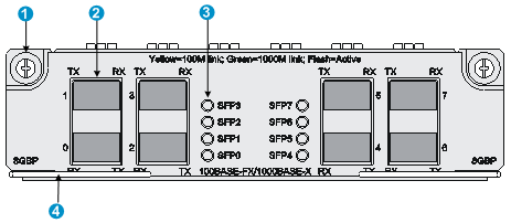
HIM-4GBP (RT-HIM-4GBP-H3)/HIM-8GBP (RT-HIM-8GBP-H3)
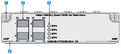
The HIM-4GBP and HIM-8GBP are high-speed Layer 3 GE interface modules. A HIM-4GBP provides 4, and a HIM-8GBP provides 8 Small Form-Factor Pluggable (SFP) ports that support Layer 3 routing. Each port is provided with a bi-color LED, which indicates the running status of the port. Connected to the processor through an SPI-4 high-speed bus, the HIM-4GBP or HIM-8GBP provides a full range of high-performance functions of Layer 3 Ethernet interfaces.
Front panels
Figure 4 Front panel of HIM-4GBP
|
(1) Captive screw |
(2) SFP port |
|
(3) SFP port status LED |
(4) Ejector lever |
Figure 5 Front panel of HIM-8GBP
|
(1) Captive screw |
(2) SFP port |
|
(3) SFP port status LED |
(4) Ejector lever |
LEDs
Table 5 LED description
|
LED status |
Description |
|
Off |
No link is present. |
|
Steady green |
A 1000 Mbps link is present. |
|
Flashing green |
The interface is receiving or sending data at 1000 Mbps. |
|
Steady yellow |
A 100 Mbps link is present. |
|
Flashing yellow |
The interface is receiving or sending data at 100 Mbps. |
Interface specifications
Table 6 Interface specifications
|
Item |
Specification |
|||||
|
Connector type |
SFP |
|||||
|
Number of interfaces |
· HIM-4GBP: 4 · HIM-8GBP: 8 |
|||||
|
Interface standards |
802.3, 802.3u, 802.3ab |
|||||
|
Supported frame format |
· Ethernet_II · Ethernet_SNAP |
|||||
|
Transmission power |
Type |
Short distance |
Medium distance |
Long distance |
Long distance |
Ultra-long distance |
|
Min. |
–9.5 dBm |
–9 dBm |
–2 dBm |
–4 dBm |
–4 dBm |
|
|
Max. |
0 dBm |
–3 dBm |
5 dBm |
1 dBm |
2 dBm |
|
|
Receiving sensitivity |
–17 dBm |
–20 dBm |
–23 dBm |
–21 dBm |
–22 dBm |
|
|
Central wavelength |
850 nm |
1310 nm |
1310 nm |
1550 nm |
1550 nm |
|
|
Fiber type |
62.5/125 μm multi-mode fiber |
9/125 μm single-mode fiber |
9/125 μm single-mode fiber |
9/125 μm single-mode fiber |
9/125 μm single-mode fiber |
|
|
Max. transmission distance |
0.55 km (0.3418 miles) |
10 km (6.21 miles) |
40 km (24.86 miles) |
40 km (24.86 miles) |
70 km (43.50 miles) |
|
|
Interface speed |
· 1000 Mbps (recommended) · Full duplex |
|||||
The following transceiver modules are available for the HIM-4GBP/HIM-8GBP:
· 100 Mbps fiber SFP transceiver modules.
· 1000 Mbps fiber SFP transceiver modules.
· 100/1000 Mbps fiber SFP transceiver modules.
· 10/100/1000 Mbps copper SFP transceiver modules (support for 10/100/1000 Mbps autosensing on the HIM-4GBP/HIM-8GBP).
Prepare the transceiver modules yourself as required.
H3C recommends that you use H3C SFP transceiver modules for the device. H3C does not guarantee the compatibility of SFP transceiver modules from other vendors with the device. The device reports an alarm when non-H3C SFP transceiver modules are installed.
Interface cables
Use interface cables for the HIM-4GBP/HIM-8GBP as follows:
· Fiber SFP transceiver module—Fibers with the LC connector.
· Copper SFP transceiver module—Category-5 straight-through or crossover twisted pair cable when the port is operating at 10/100 Mbps and Category-6 twisted pair cable when the port is operating at 1000 Mbps.
For the appearance and connection of a HIM-4GBP/HIM-8GBP interface cable, see "Connecting an Ethernet interface cable" or "Connecting an optical interface cable."
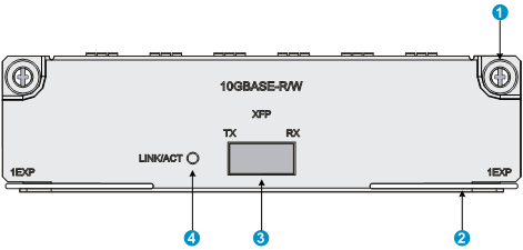
HIM-1EXP (RT-HIM-1EXP-H3)
The HIM-1EXP is a 1-port 10 GE transceiver module. It provides one 10-Gigabit Small Form-Factor Pluggable (XFP) port and supports switchover between LAN/WAN PHY modes. A LED is provided on the front panel to show the operation state.
Front panel
|
(1) Captive screw |
(2) Ejector lever |
|
(3) XFP port |
(4) XFP port carrier signal LED (LINK/ACT) |
LED
Table 7 LED description
|
LED status |
Description |
|
Off |
No link is present. |
|
Steady green |
A link is present, but no data is being received or transmitted. |
|
Flashing green |
The XFP port is receiving or sending data. |
Interface specifications
Table 8 Interface specifications
|
Item |
Specification |
|||
|
Connector type |
XFP/LC |
|||
|
Number of interfaces |
1 |
|||
|
Supported frame format |
10GBase-R/W |
|||
|
Interface speed |
· LAN PHY mode: 10.3125 Gbps · WAN PHY mode: 9.95328 Gbps |
|||
|
Optical transmit power |
Type |
Short distance |
Medium distance |
Long distance |
|
Min. |
–7.3 dBm |
–8.2 dBm |
–1 dBm |
|
|
Max. |
–1.08 dBm |
0.5 dBm |
2 dBm |
|
|
Receiving sensitivity |
–7.5 dBm |
–10.3 dBm |
–11.3 dBm |
|
|
Central wavelength |
850 nm |
1310 nm |
1550 nm |
|
|
Max. transmission distance |
0.3 km (0.19 miles) |
10 km (6.21 miles) |
40 km (24.86 miles) |
|
|
Fiber type |
62.5/125 μm multi-mode |
9/125 μm single-mode |
9/125 μm single-mode |
|
|
|
NOTE: In LAN PHY mode, 10GBase-R is supported. In WAN PHY mode, 10GBase-W is supported. |
Interface cables
The HIM-1EXP must work with an XFP transceiver module and an optical fiber with LC-type connectors. For the appearance and connection of a HIM-1EXP interface cable, see "Connecting an optical interface cable."
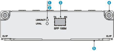
HIM-CL1P (RT-HIM-1CPOS/STM1-H3)/HIM-CL2P (RT-HIM-2CPOS/STM1-H3)
The HIM-CL1P and HIM-CL2P are high-speed OC-3/STM-1 (155 Mbps) channelized packet over SONET/SDH (CPOS) E1/T1 interface modules. The HIM-CL1P provides one SFP port and the port is provided with two LEDs, which indicate the port running status and fault detection status, respectively. The HIM-CL2P provides two SFP ports.
The HIM-CL1P/HIM-CL2P has the following features:
· Connects to the processor through a 10-Gbps high-speed bus. Each CPOS interface can be channelized into 63 E1s or 84 T1s, and it can be channelized into 512 DS0s.
· Receives multiplexed E1/T1 circuits on a pair of fibers through a channelized interface, saving many link resources, the occupied area, and the cost of local networks and devices for telecommunication service providers and large enterprises.
· Supports IP and MPLS traffic and the Multi-link Point-to-Point Protocol (MP), and supports up to 12 E1s or T1s in each MP bundle.
· Uses hardware-based MP bundling. This solves the problem of low efficiency of MP bundling, and improving the access density of user devices.
· Supports two operating modes that can be configured at the CLI: CPOS E1 and CPOS T1.
· The operating mode configuration takes effect only after you hot-swap the interface module or reboot the device. H3C recommends that you remove and insert the module to bring the configuration into effect.
· The operating mode configuration takes effect for all the interfaces on the interface module.
|
|
NOTE: · The HIM-CL1P/HIM-CL2P does not support cascading and non-channelized SDH and SONET. · The HIM-CL1P/HIM-CL2P does not support channelizing OC-3/STM-1 into DS3s or E3s. |
Front panels
Figure 7 Front panel of HIM-CL1P
|
(1) SFP port carrier signal LED (LINK/ACT) |
(2) SFP port loopback/alarm LED (LP/AL) of SFP port |
|
(3) SFP port |
(4) Captive screw |
|
(5) Ejector lever |
|
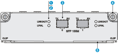
Figure 8 Front panel of HIM-CL2P
|
(1) SFP port carrier signal LED (LINK/ACT) |
(2) SFP port loopback/alarm LED (LP/AL) |
|
(3) SFP port |
(4) Captive screw |
|
(5) Ejector lever |
|
LEDs
Table 9 LED description
|
LED |
Status |
Description |
|
LINK/ACT (Green) |
Off |
No link is present. |
|
On |
A 155.52 Mbps link is present. |
|
|
Flashing |
The SFP port is receiving or sending data at 155.52 Mbps. |
|
|
LP/AL (Yellow) |
Off |
No loopback or alarm exists. |
|
On |
The port is in loopback state. |
|
|
Flashing |
There is a minimum of one alarm. |
Interface specifications
Table 10 Interface specifications
|
Item |
Specification |
||||
|
Connector type |
SFP/LC |
||||
|
Number of interfaces |
· HIM-CL1P: 1 · HIM-CL2P: 2 |
||||
|
Interface standards |
SONET OC-3/SDH STM-1 |
||||
|
Interface speed |
155.52 Mbps |
||||
|
Optical transmit power |
Type |
Short distance |
Medium distance |
Long distance |
Ultra-long distance |
|
Min. |
–19.0 dBm |
–15.0 dBm |
–5.0 dBm |
–5.0 dBm |
|
|
Max. |
–14.0 dBm |
–8.0 dBm |
0 dBm |
0 dBm |
|
|
Receiving sensitivity |
–30.0 dBm |
–28.0 dBm |
–34.0 dBm |
–34.0 dBm |
|
|
Overload optical power |
–14.0 dBm |
–7.0 dBm |
–9.0 dBm |
–10.0 dBm |
|
|
Central wavelength |
1310 nm |
1310 nm |
1310 nm |
1550 nm |
|
|
Max. transmission distance |
2 km (1.24 miles) |
15 km (9.32 miles) |
40 km (24.86 miles) |
80 km (49.71 miles) |
|
|
Fiber type |
62.5/125 μm multi-mode |
9/125 μm single-mode |
9/125 μm single-mode |
9/125 μm single-mode |
|
Interface cables
The HIM-CL1P/HIM-CL2P must work with an SFP transceiver module and an optical fiber that have LC-type connectors. For the appearance and connection of a HIM-CL1P/HIM-CL2P interface cable, see "Connecting an optical interface cable."
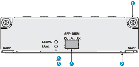
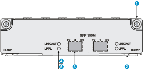
HIM-CLS1P (RT-HIM-CLS1P-H3)/HIM-CLS2P (RT-HIM-CLS2P-H3)
The HIM-CLS1P and HIM-CLS2P are high-speed OC-3/STM-1 (155 Mbps) CPOS E3/T3 interface modules. They can also operate in packet over SONET/SDH (POS) mode. The HIM-CLS1P provides one SFP port and the port is provided with two LEDs, which indicate the port running status and fault detection status, respectively. The HIM-CLS2P provides two SFP ports.
The HIM-CLS1P/HIM-CLS2P has the following features:
· Connects to the processor through a 10-Gbps high-speed bus. Each OC-3/STM-1 POS interface can be channelized into three E3s or T3s.
· Each E3/T3 channel supports the subrate processing capability, providing users with a variety of bandwidth options.
· Receives multiplexed E3/T3 circuits on a pair of fibers through a channelized interface, saving many link resources, the occupied area, and the cost of local networks and devices for telecommunication service providers and large enterprises.
· Supports IP and MPLS traffic and MP with up to three E3s or T3s in each MP bundle.
· Supports three operating modes that can be configured at the CLI: CPOS E3, CPOS T3, or POS (155 Mbps).
· The configuration of the operating mode can take effect only after you hot-plug the interface module or reboot the device. It is recommended to remove and insert the module to bring the configuration into effect.
· The configuration of the operating mode takes effect for all the interfaces on the interface modules.
|
|
NOTE: The HIM-CLS1P/HIM-CLS2P does not support channelizing OC-3/STM-1 into DS1s or E1s. |
Front panels
Figure 9 Front panel of HIM-CLS1P
|
(1) Captive screw |
(2) Ejector lever |
|
(3) SFP port |
(4) SFP port carrier signal LED (LINK/ACT) |
|
(5) SFP port loopback/alarm LED (LP/AL) |
|
Figure 10 Front panel of HIM-CLS2P
|
(1) Captive screw |
(2) Ejector lever |
|
(3) SFP port |
(4) SFP port carrier signal LED (LINK/ACT) |
|
(5) SFP port loopback/alarm LED (LP/AL) |
|
LEDs
Table 11 LED description
|
LED |
Status |
Description |
|
LINK/ACT (Green) |
Off |
No link is present. |
|
On |
A 155.52 Mbps link is present. |
|
|
Flashing |
The SFP port is receiving or sending data at 155.52 Mbps. |
|
|
LP/AL (Yellow) |
Off |
No loopback or alarm exists. |
|
On |
The interface is in loopback state. |
|
|
Flashing |
There is a minimum of one alarm. |
Interface specifications
Table 12 Interface specifications
|
Item |
Specification |
||||
|
Connector type |
SFP/LC |
||||
|
Number of interfaces |
· HIM-CLS1P: 1 · HIM-CLS2P: 2 |
||||
|
Interface standards |
SONET OC-3/SDH STM-1 |
||||
|
Interface speed |
155.52 Mbps |
||||
|
Optical transmit power |
Type |
Short distance |
Medium distance |
Long distance |
Ultra-long distance |
|
Min. |
–19.0 dBm |
–15.0 dBm |
–5.0 dBm |
–5.0 dBm |
|
|
Max. |
–14.0 dBm |
–8.0 dBm |
0 dBm |
0 dBm |
|
|
Receiving sensitivity |
–30.0 dBm |
–28.0 dBm |
–34.0 dBm |
–34.0 dBm |
|
|
Overload optical power |
–14.0 dBm |
–7.0 dBm |
–9.0 dBm |
–10.0 dBm |
|
|
Central wavelength |
1310 nm |
1310 nm |
1310 nm |
1550 nm |
|
|
Max. transmission distance |
2 km (1.24 miles) |
15 km (9.32 miles) |
40 km (24.86 miles) |
80 km (49.71 miles) |
|
|
Fiber type |
62.5/125 μm multi-mode |
9/125 μm single-mode |
9/125 μm single-mode |
9/125 μm single-mode |
|
Interface cables
The HIM-CLS1P/HIM-CLS2P must work with an SFP transceiver module and an optical fiber with LC-type connectors. For the appearance and connection of a HIM-CLS1P/HIM-CLS2P interface cable, see "Connecting an optical interface cable."
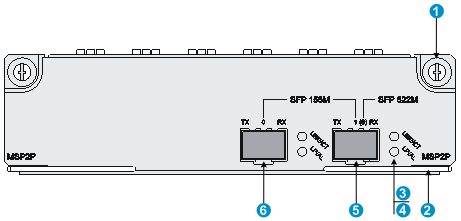
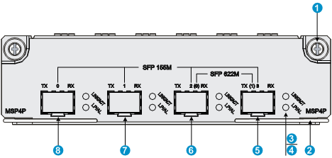
HIM-MSP2P (RT-HIM-MSP2P-H3)/HIM-MSP4P (RT-HIM-MSP4P-H3)
The HIM-MSP2P/HIM-MSP4P is a high-speed OC-3/STM-1 (155 Mbps) and OC-12/STM-4 (622 Mbps) non-channelized POS interface module. The HIM-MSP2P/HIM-MSP4P supports PPP, Frame Relay, and HDLC at the data link layer and IP at the network layer.
When using the HIM-MSP2P/HIM-MSP4P, follow these guidelines:
· You can use the card-mode command to configure the interface module to operate in OC-3/STM-1 POS or OC-12/STM-4 POS mode.
· The configuration of the operating mode can take effect only after you hot-swap the interface module or reboot the device. It is recommended to remove and insert the module to bring the configuration into effect.
· The configuration of the operating mode takes effect for all the interfaces on the interface module.
· The interface module supports multi-mode short distance (1310 nm), single-mode medium distance (1310 nm), single-mode long distance (1310 nm), and single-mode ultra-long distance (1550 nm) transceiver modules.
|
|
NOTE: The HIM-MSP2P/HIM-MSP4P is an optional interface module to be separately ordered if needed. |
Front panels
Figure 11 Front panel of HIM-MSP2P
|
(1) Captive screw |
(2) Ejector lever |
|
(3) SFP port carrier signal LED (LINK/ACT) |
(4) SFP port loopback/alarm LED (LP/AL) |
|
(5) SFP port 1 (155 Mbps)/SFP port 0 (622 Mbps) |
(6) SFP port 0 (155 Mbps) |
|
(1) Captive screw |
(2) Ejector lever |
|
(3) SFP port carrier signal LED (LINK/ACT) |
(4) SFP port loopback/alarm LED (LP/AL) |
|
(5) SFP port 3 (155 Mbps) or SFP port 1 (622 Mbps) |
|
|
(6) SFP port 2 (155 Mbps) or SFP port 0 (622 Mbps) |
|
|
(7) SFP port 1 (155 Mbps) |
(8) SFP port 0 (155 Mbps) |
LEDs
Table 13 LED description
|
LED |
Status |
Description |
|
LINK/ACT (Green) |
Off |
No link is present. |
|
On |
A 155.52/622.08 Mbps link is present. |
|
|
Flashing |
The SFP port is receiving or sending data at 155.52/622.08 Mbps. |
|
|
LP/AL (Yellow) |
Off |
No loopback or alarm exists. |
|
On |
The port is in loopback state. |
|
|
Flashing |
There is a minimum of one alarm. |
Interface specifications
Table 14 Interface specifications
|
Item |
Specification |
|||||||
|
Connector type |
SFP/LC |
|||||||
|
Number of interfaces |
· HIM-MSP2P: 2 OC-3 interfaces or 1 OC-12 interface · HIM-MSP4P: 4 OC-3 interfaces or 2 OC-12 interfaces |
|||||||
|
Interface standards |
· SONET STS-3/STS-12 · SDH STM-1/STM-4 |
|||||||
|
Interface speed |
155.52/622.08 Mbps |
|||||||
|
OC-3 interface (155.52 Mbps) |
||||||||
|
Optical transit power |
Type |
Short distance |
Medium distance |
Long distance |
Ultra-long distance |
|||
|
Min. |
–19.0 dBm |
–15.0 dBm |
–5.0 dBm |
–5.0 dBm |
||||
|
Max. |
–14.0 dBm |
–8.0 dBm |
0 dBm |
0 dBm |
||||
|
Receiving sensitivity |
–30.0 dBm |
–28.0 dBm |
–34.0 dBm |
–34.0 dBm |
||||
|
Overload optical power |
–14.0 dBm |
–7.0 dBm |
–9.0 dBm |
–10.0 dBm |
||||
|
Central wavelength |
1310 nm |
1310 nm |
1310 nm |
1550 nm |
||||
|
Max. transmission distance |
2 km (1.24 miles) |
15 km (9.32 miles) |
40 km (24.86 miles) |
80 km (49.71 miles) |
||||
|
62.5/125 μm multi-mode |
9/125 μm single-mode |
9/125 μm single-mode |
9/125 μm single-mode |
|||||
|
OC-12 interface (622.08 Mbps) |
||||||||
|
Optical transit power |
Type |
Medium distance |
Long distance |
Ultra-long distance |
||||
|
Min. |
–15.0 dBm |
–3.0 dBm |
–3 dBm |
|||||
|
Max. |
–8.0 dBm |
2.0 dBm |
2.0 dBm |
|||||
|
Receiving sensitivity |
–28.0 dBm |
–28.0 dBm |
–28 dBm |
|||||
|
Overload optical power |
–8.0 dBm |
–8.0 dBm |
–8 dBm |
|||||
|
Central wavelength |
1310 nm |
1310 nm |
1550 nm |
|||||
|
Max. transmission distance |
15 km (9.32 miles) |
40 km (24.86 miles) |
80 km (49.71 miles) |
|||||
|
Fiber type |
9/125 μm single-mode |
9/125 μm single-mode |
9/125 μm single-mode |
|||||
Interface cables
The HIM-MSP2P/HIM-MSP4P must work with an SFP transceiver module and an optical fiber with LC-type connectors. For the appearance and connection of a HIM-MSP2P/HIM-MSP4P interface cable, see "Connecting an optical interface cable."
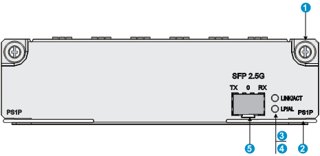
HIM-PS1P (RT-HIM-1POS/STM16-H3)
The HIM-PS1P is a high-speed OC-48/STM-16 (2.5 Gbps) CPOS or non-channelized POS interface module. It supports PPP, Frame Relay, and HDLC at the data link layer and IP at the network layer. It provides POS interfaces for direct transmission of data packets over SONET/SDH.
When using the HIM-PS1P, follow these guidelines:
· The interface module can run in E-CPOS mode or OC-48/STM-16 POS mode.
· The interface module supports multi-mode short distance (1310 nm), single-mode medium distance (1310 nm), single-mode long distance (1310 nm), and single-mode ultra-long distance (1550 nm) transceiver modules.
The HIM-PS1P is an optional module to be separately ordered if needed.
Front panel
Figure 13 Front panel of HIM-PS1P
|
(1) Captive screw |
(2) Ejector lever |
|
(3) SFP port carrier signal LED (LINK/ACT) |
(4) SFP port loopback/alarm LED (LP/AL) |
|
(5) SFP port (2.5 Gbps) |
|
LEDs
Table 15 LED description
|
LED |
Status |
Description |
|
LINK/ACT (Green) |
Off |
No link is present. |
|
On |
A 2488.32 Mbps link is present. |
|
|
Flashing |
The SFP port is receiving or sending data at 2488.32 Mbps. |
|
|
LP/AL (Yellow) |
Off |
No loopback or alarm exists. |
|
On |
The interface is in loopback state. |
|
|
Flashing |
There is a minimum of one alarm. |
Interface specifications
Table 16 Interface specifications
|
Item |
Specification |
||||
|
Connector type |
SFP/LC |
||||
|
Number of interfaces |
1 OC-48 interface |
||||
|
Interface standards |
· SONET STS-48 · SDH STM-16 |
||||
|
Interface speed |
2488.32 Mbps |
||||
|
Optical transit power |
Type |
Short distance |
Medium distance |
Long distance |
Ultra-long distance |
|
Min. |
–10.0 dBm |
–5.0 dBm |
–2.0 dBm |
–2.0 dBm |
|
|
Max. |
–3.0 dBm |
0 dBm |
3.0 dBm |
3.0 dBm |
|
|
Receiving sensitivity |
–18.0 dBm |
–18.0 dBm |
–27.0 dBm |
–28.0 dBm |
|
|
Overload optical power |
–3.0 dBm |
0.0 dBm |
–9.0 dBm |
–8.0 dBm |
|
|
Central wavelength |
1310 nm |
1310 nm |
1310 nm |
1550 nm |
|
|
Max. transmission distance |
2 km (1.24 miles) |
15 km (9.32 miles) |
40 km (24.86 miles) |
80 km (49.71 miles) |
|
|
Fiber type |
9/125 μm single-mode |
9/125 μm single-mode |
9/125 μm single-mode |
9/125 μm single-mode |
|
Interface cables
The HIM-PS1P must work with an SFP transceiver module and an optical fiber with LC-type connectors. For the appearance and connection of a HIM-PS1P interface cable, see "Connecting an optical interface cable."
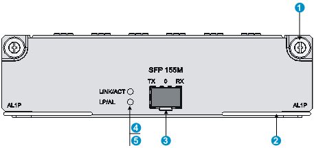
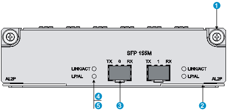
HIM-AL1P (RT-HIM-AL1P-H3)/HIM-AL2P (RT-HIM-AL2P-H3)
The HIM-AL1P and HIM-AL2P are OC-3/STM-1 (155 Mbps) Asynchronous Transfer Mode (ATM) interface modules. The HIM-AL1P provides an SFP port and the port is provided with two LEDs, which indicate the interface running status and fault detection status, respectively. The HIM-AL2P provides two SFP ports.
The HIM-AL1P/HIM-AL2P has the following features:
· Supports frame formats of SDH STM-1 and SONET OC-3C.
· Allows data scrambling transmission.
· Supports line clock mode and internal clock mode.
· Provides self loopback testing measures such as internal cell loopback, external SONET/SDH loopback, and remote loopback.
· Supports hot swapping.
Front panels
Figure 14 Front panel of HIM-AL1P
|
(1) Captive screw |
(2) Ejector lever |
|
(3) SFP port |
(4) SFP port carrier signal LED (LINK/ACT) |
|
(5) SFP port loopback/alarm LED (LP/AL) |
|
Figure 15 Front panel of HIM-AL2P
|
(1) Captive screw |
(2) Ejector lever |
|
(3) SFP port |
(4) SFP port carrier signal LED (LINK/ACT) |
|
(5) SFP port loopback/alarm LED (LP/AL) |
|
LEDs
Table 17 LED description
|
LED |
Status |
Description |
|
LINK/ACT (Green) |
Off |
No link is present. |
|
On |
A 155.52 Mbps link is present. |
|
|
Flashing |
The SFP port is receiving or sending data at 155.52 Mbps. |
|
|
LP/AL (Yellow) |
Off |
No loopback or alarm exists. |
|
On |
The port is in loopback state. |
|
|
Flashing |
There is a minimum of one alarm. |
Interface specifications
Table 18 Interface specifications
|
Item |
Specification |
||||
|
Connector type |
SFP/LC |
||||
|
Number of interfaces |
· HIM-AL1P: 1 · HIM-AL2P: 2 |
||||
|
Interface standards |
SONET OC-3C/SDH STM-1 |
||||
|
Interface speed |
155.52 Mbps |
||||
|
Optical transit power |
Type |
Short distance |
Medium distance |
Long distance |
Ultra-long distance |
|
Min. |
–19.0 dBm |
–15.0 dBm |
–5.0 dBm |
–5.0 dBm |
|
|
Max. |
–14.0 dBm |
–8.0 dBm |
0 dBm |
0 dBm |
|
|
Receiving sensitivity |
–30.0 dBm |
–28.0 dBm |
–34.0 dBm |
–34.0 dBm |
|
|
Overload optical power |
–14.0 dBm |
7.0 dBm |
–9.0 dBm |
–10.0 dBm |
|
|
Central wavelength |
1310 nm |
1310 nm |
1310 nm |
1550 nm |
|
|
Max. transmission distance |
2 km (1.24 miles) |
15 km (9.32 miles) |
40 km (24.86 miles) |
80 km (49.71 miles) |
|
|
Fiber type |
62.5/125 μm multi-mode |
9/125 μm single-mode |
9/125 μm single-mode |
9/125 μm single-mode |
|
Interface cables
The HIM-AL1P/HIM-AL2P must work with an SFP transceiver module and an optical fiber with LC-type connectors. For the appearance and connection of a HIM-AL1P/HIM-AL2P interface cable, see "Connecting an optical interface cable."
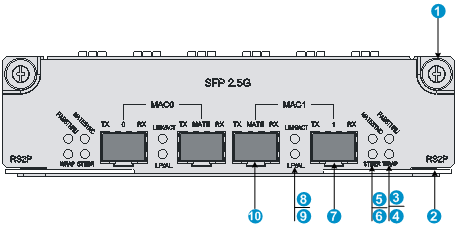
HIM-RS2P (RT-HIM-RS2P-H3)
The HIM-RS2P is a 2.5 Gbps OC-48/STM-16 Resilient Packet Ring (RPR) interface module. It provides two SFP RPR ports and two SFP Mate ports. Each RPR port is provided with six status LEDs, which show the running status and fault detection status of RPR and optical interface at the physical layer.
The HIM-RS2P supports:
· Two frame formats: SDH STM-16 and SONET OC-48C.
· Line clock mode and internal clock mode.
· Loopback tests such as data loopback test, external SONET/SDH loopback test, and external link loopback test.
· Hot swapping.
Front panel
|
(1) Captive screw |
(2) Ejector lever |
|
(3) PASSTHRU LED of the MAC RPR node |
(4) WRAP LED of MAC RPR node |
|
(5) MAC MATE interface LED |
(6) STEER LED of the MAC RPR node |
|
(7) External SFP port of the MAC RPR node |
|
|
(8) MAC external SFP port carrier signal LED (LINK/ACT) |
|
|
(9) MAC external SFP port loopback/alarm LED (LP/AL) |
(10) Mate interface of the MAC RPR node |
LEDs
Table 19 LED description
|
LED |
Status |
Description |
|
|
RPR status |
PASSTHRU (Green) |
Off |
The node is not in PASSTHRU. |
|
On |
The node is in PASSTHRU. |
||
|
MATESYNC (Green) |
Off |
The mate interface is not synchronized. |
|
|
On |
The mate interface is synchronized. |
||
|
WRAP (Yellow) |
Off |
No WRAP exists. |
|
|
On |
WRAP occurs on this node. |
||
|
Flashing (0.5 Hz) |
WRAP occurs on another node. |
||
|
STEER (Yellow) |
Off |
No STEER exists. |
|
|
On |
STEER occurs on this node. |
||
|
Flashing (0.5 Hz) |
STEER occurs on another node. |
||
|
External optical interface SDH/SONET at physical layer |
LINK/ACT (Green) |
Off |
No carrier signals are being received. |
|
On |
Carrier signals are being received. |
||
|
Flashing (4 Hz) |
Data is being transmitted or received. |
||
|
LP/AL (Yellow) |
Off |
No loopback or alarms occur. |
|
|
On |
The port is in loopback state. |
||
|
Flashing (0.5 Hz) |
A minimum of one alarm, AIS, LFA, or RAI, occurs. |
||
Interface specifications
Table 20 Interface specifications
|
Item |
Specification |
||||
|
Connector type |
SFP/LC |
||||
|
Number of interfaces |
4 |
||||
|
Interface standards |
· SONET STS-48 · SDH STM-16 |
||||
|
Interface speed |
2488.32 Mbps |
||||
|
Optical transmit power |
Type |
Short distance |
Medium distance |
Long distance |
Ultra-long distance |
|
Min. |
–10.0 dBm |
–5.0 dBm |
–2.0 dBm |
–2.0 dBm |
|
|
Max. |
–3.0 dBm |
0 dBm |
3.0 dBm |
3.0 dBm |
|
|
Receiving sensitivity |
–18.0 dBm |
–18.0 dBm |
–27.0 dBm |
–28.0 dBm |
|
|
Overload optical power |
–3.0 dBm |
0 dBm |
–9.0 dBm |
–8.0 dBm |
|
|
Central wavelength |
1310 nm |
1310 nm |
1310 nm |
1550 nm |
|
|
Max. transmission distance |
2 km (1.24 miles) |
15 km (9.32 miles) |
40 km (24.86 miles) |
80 km (49.71 miles) |
|
|
Fiber type |
9/125 μm single-mode |
9/125 μm single-mode |
9/125 μm single-mode |
9/125 μm single-mode |
|
Interface cables
Test optical power before choosing a transceiver module and optical fiber, because an optical fiber connector might have transmitted for dozens of kilometers from a user fiber.
The HIM-RS2P supports the connection of Mate interfaces within the module. All Mate interfaces in a module can be connected without external transceiver modules or fibers.
For the appearance and connection of a HIM-RS2P interface cable, see "Connecting an optical interface cable."
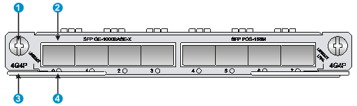
HIM-4G4P (RT-HIM-4G4P-H3)
The HIM-4G4P provides 4 Packet Over SDH/SONET (POS) interfaces and four 1000 Mbps Ethernet fiber ports. A POS interface transmits data at STM-1/OC-3 (155.52Mbps). The HIM-4G4P is half the height of a HIM, and occupies one slot on a FIP.
Front panel
Figure 17 Front panel
|
(1) Captive screw |
(2) SFP port |
|
(3) Ejector lever |
(4) SFP port carrier signal LED (LINK/ACT) |
LEDs
Table 21 LED description
|
LED |
Status |
Description |
|
|
SFP GE-1000Base-X |
LINK/ACT (0 to 3) (Green) |
Off |
No link is present. |
|
On |
A 1000 Mbps link is present. |
||
|
Flashing |
Data is being transmitted or received at 1000 Mbps. |
||
|
SFP POS-155M |
LINK/ACT/LP/AL (4 to 7) (Yellow/Green) |
Steady green |
A 155.52 Mbps link is present. |
|
Flashing green |
Data is being transmitted or received. |
||
|
Steady yellow |
A loopback exists. |
||
|
Flashing yellow |
An alarm has occurred. |
||
|
Off |
No link is present. |
||
Interface specifications
Table 22 Ethernet fiber port specifications
|
Item |
Specification |
|||||
|
Connector type |
SFP |
|||||
|
Number of interfaces |
4 |
|||||
|
Interface standards |
802.3, 802.3u, 802.3ab |
|||||
|
Frame format |
Ethernet_II Ethernet_SNAP |
|||||
|
Optical transmit power |
Type |
Short distance |
Medium distance |
Long distance |
Long distance |
Ultra-long distance |
|
Min. |
–9.5 dBm |
–9 dBm |
–2 dBm |
–4 dBm |
–4 dBm |
|
|
Max. |
0 dBm |
–3 dBm |
5 dBm |
1 dBm |
2 dBm |
|
|
Receiving sensitivity |
–17 dBm |
–20 dBm |
–23 dBm |
–21 dBm |
–22 dBm |
|
|
Central wavelength |
850 nm |
1310 nm |
1310 nm |
1550 nm |
1550 nm |
|
|
Max. transmission distance |
0.55 km (0.34 miles) |
10 km (6.21 miles) |
40 km (24.86 miles) |
40 km (24.86 miles) |
70 km (43.50 miles) |
|
|
Fiber type |
62.5/125 μm multi-mode |
9/125 μm single-mode |
9/125 μm single-mode |
9/125 μm single-mode |
9/125 μm single-mode |
|
Table 23 POS interface specifications
|
Item |
Specification |
||||
|
Connector type |
SFP |
||||
|
Number of interfaces |
4 |
||||
|
Interface standards |
SONET OC-3 SDH STM-1 |
||||
|
Interface speed |
155.52 Mbps |
||||
|
Optical transmit power |
Type |
Short distance |
Medium distance |
Long distance |
Ultra-long distance |
|
Min. |
–19.0 dBm |
–15.0 dBm |
–5.0 dBm |
–5.0 dBm |
|
|
Max. |
–14.0 dBm |
–8.0 dBm |
0 dBm |
0 dBm |
|
|
Receiving sensitivity |
–30.0 dBm |
–28.0 dBm |
–34.0 dBm |
–34.0 dBm |
|
|
Overload optical power |
–14.0 dBm |
–7.0 dBm |
–9.0 dBm |
–10.0 dBm |
|
|
Central wavelength |
1310 nm |
1310 nm |
1310 nm |
1550 nm |
|
|
Max. transmission distance |
2 km (1.24 miles) |
15 km (9.32 miles) |
40 km (24.86 miles) |
80 km (49.71 miles) |
|
|
Fiber type |
62.5/125 μm multi-mode |
9/125 μm single-mode |
9/125 μm single-mode |
9/125 μm single-mode |
|
The Ethernet fiber ports of the HIM-4G4P support 1000 Mbps SFP fiber transceiver modules 1000 Mbps SFP copper transceiver modules, and the POS interfaces support 155 Mbps SFP fiber transceiver modules.
The transceiver modules are optional.
Interface cables
The HIM-4G4P is used together with SFP transceiver modules and fibers with LC connectors.
For the appearance and connection of a HIM-4G4P interface cable, see "Connecting an optical interface cable."
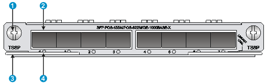
HIM-TS8P (RT-HIM-TS8P-H3)
The HIM-TS8P provides 8 ports, each of which can be switched between a POS interface and an Ethernet port. A POS interface transmits data at OC-3/STM-1 (155.52Mbps) or OC-12/STM-4 (622Mbps). An Ethernet port transmits data at 1000 Mbps. The HIM-TS8P is half the height of a HIM, and occupies one slot on a FIP.
To switch the interface type of a HIM-TS8P, use the port-type switch command.
To switch the POS interface speed of a HIM-TS8P, use the speed command in POS interface view.
For more information about the port-type switch and speed commands, see H3C SR6600/SR6600-X Routers Interface Command Reference.
Front panel
Figure 18 Front panel
|
(1) Captive screw |
(2) SFP port |
|
(3) Ejector lever |
(4) SFP port carrier signal LED (LINK/ACT) |
LEDs
Table 24 LED description
|
LED |
Status |
Description |
|
|
SFP GE-1000Base-X |
LINK/ACT (Green) |
Off |
No link is present. |
|
On |
A 1000 Mbps link is present. |
||
|
Flashing |
Data is being transmitted or received at 1000 Mbps. |
||
|
SFP POS-155M/POS-622M |
LINK/ACT/LP/AL (Yellow/Green) |
Steady green |
A 155.52/622 Mbps link is present. |
|
Flashing green |
Data is being transmitted or received. |
||
|
Steady yellow |
A loopback exists. |
||
|
Flashing yellow |
An alarm has occurred. |
||
|
Off |
No link is present. |
||
Interface specifications
Table 25 Ethernet fiber port specifications
|
Item |
Specification |
|||||
|
Connector type |
SFP |
|||||
|
Number of interfaces |
0 to 8 |
|||||
|
Interface standards |
802.3, 802.3u, 802.3ab |
|||||
|
Frame format |
Ethernet_II Ethernet_SNAP |
|||||
|
Optical transmit power |
Type |
Short distance |
Medium distance |
Long distance |
Long distance |
Ultra-long distance |
|
Min. |
–9.5 dBm |
–9 dBm |
-–2 dBm |
–4 dBm |
–4 dBm |
|
|
Max. |
0 dBm |
–3 dBm |
5 dBm |
1 dBm |
2 dBm |
|
|
Receiving sensitivity |
–17 dBm |
–20 dBm |
–23 dBm |
–21 dBm |
–22 dBm |
|
|
Central wavelength |
850 nm |
1310 nm |
1310 nm |
1550 nm |
1550 nm |
|
|
Max. transmission distance |
0.55 km (0.34 miles) |
10 km (6.21 miles) |
40 km (24.86 miles) |
40 km (24.86 miles) |
70 km (43.50 miles) |
|
|
Fiber type |
62.5/125 μm multi-mode |
9/125 μm single-mode |
9/125 μm single-mode |
9/125 μm single-mode |
9/125 μm single-mode |
|
Table 26 POS interface specifications
|
Item |
Specification |
|||||||
|
Connector type |
SFP |
|||||||
|
Number of interfaces |
0 to 8 |
|||||||
|
Interface standards |
· SONET STS-3/STS-12 · SDH STM-1/STM-4 |
|||||||
|
Interface speed |
155.52 Mbps 622.08 Mbps |
|||||||
|
OC-3 interface (155.52 Mbps) |
||||||||
|
Optical transmit power |
Type |
Short distance |
Medium distance |
Long distance |
Ultra-long distance |
|||
|
Min. |
–19.0 dBm |
–15.0 dBm |
–5.0 dBm |
–5.0 dBm |
||||
|
Max. |
–14.0 dBm |
–8.0 dBm |
0 dBm |
0 dBm |
||||
|
Receiving sensitivity |
–30.0 dBm |
–28.0 dBm |
–34.0 dBm |
–34.0 dBm |
||||
|
Overload optical power |
–14.0 dBm |
–7.0 dBm |
–9.0 dBm |
–10.0 dBm |
||||
|
Central wavelength |
1310 nm |
1310 nm |
1310 nm |
1550 nm |
||||
|
Max. transmission distance |
2 km (1.24 miles) |
15 km (9.32 miles) |
40 km (24.86 miles) |
80 km (49.71 miles) |
||||
|
Fiber type |
62.5/125 μm multi-mode |
9/125 μm single-mode |
9/125 μm single-mode |
9/125 μm single-mode |
||||
|
OC-12 interface (622.08 Mbps) |
||||||||
|
Optical transmit power |
Type |
Medium distance |
Long distance |
Ultra-long distance |
||||
|
Min. |
–15.0 dBm |
–3.0 dBm |
–3.0 dBm |
|||||
|
Max. |
–8.0 dBm |
2.0 dBm |
2.0 dBm |
|||||
|
Receiving sensitivity |
–28.0 dBm |
–28.0 dBm |
–28.0 dBm |
|||||
|
Overload optical power |
–8.0 dBm |
–8.0 dBm |
–8.0 dBm |
|||||
|
Central wavelength |
1310 nm |
1310 nm |
1550 nm |
|||||
|
Max. transmission distance |
15 km (9.32 miles) |
40 km (24.86 miles) |
80 km (49.71 miles) |
|||||
|
Fiber type |
9/125 μm single-mode |
9/125 μm single-mode |
9/125 μm single-mode |
|||||
The Ethernet fiber ports of the HIM-TS8P support 1000 Mbps SFP fiber transceiver modules 1000 Mbps SFP copper transceiver modules, and the POS interfaces support 155/622 Mbps SFP fiber transceiver modules.
The transceiver modules are optional.
Interface cables
The HIM-TS8P is used together with SFP transceiver modules and fibers with LC connectors.
For the appearance and connection of a HIM-4G4P interface cable, see "Connecting an optical interface cable."
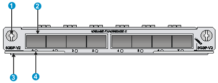
HIM-8GBP-V2
The HIM-8GBP-V2 interface module provides eight SFP ports. Each SFP port has a double-color LED to indicate its operating status. The HIM-8GBP-V2 interface module is half the height of a typical HIM, and occupies one slot on a FIP.
Front panel
Figure 19 Front panel
|
(1) Captive screw |
(2) SFP port |
|
(3) Ejector lever |
(4) SFP port LED |
LED
Table 27 LED description
|
Status |
Description |
|
Off |
No link is present. |
|
Steady green |
A 1000 Mbps link is present. |
|
Flashing green |
Data is being transmitted or received at 1000 Mbps. |
|
Steady yellow |
A 100 Mbps link is present. |
|
Flashing yellow |
Data is being transmitted or received at 100 Mbps. |
Interface specifications
Table 28 SFP port specifications
|
Item |
Specification |
|||||
|
Connector type |
SFP |
|||||
|
Number of interfaces |
8 |
|||||
|
Interface standards |
802.3, 802.3u, 802.3ab |
|||||
|
Frame format |
· Ethernet_II · Ethernet_SNAP |
|||||
|
Optical transmit power |
Type |
Short distance |
Medium distance |
Long distance |
Long distance |
Ultra-long distance |
|
Min. |
–9.5 dBm |
–9 dBm |
-–2 dBm |
–4 dBm |
–4 dBm |
|
|
Max. |
0 dBm |
–3 dBm |
5 dBm |
1 dBm |
2 dBm |
|
|
Receiving sensitivity |
–17 dBm |
–20 dBm |
–23 dBm |
–21 dBm |
–22 dBm |
|
|
Central wavelength |
850 nm |
1310 nm |
1310 nm |
1550 nm |
1550 nm |
|
|
Max. transmission distance |
0.55 km (0.34 miles) |
10 km (6.21 miles) |
40 km (24.86 miles) |
40 km (24.86 miles) |
70 km (43.50 miles) |
|
|
Fiber type |
62.5/125 μm multi-mode |
9/125 μm single-mode |
9/125 μm single-mode |
9/125 μm single-mode |
9/125 μm single-mode |
|
|
Transmission rate |
· 100/1000 Mbps, half/full duplex |
|||||
The following transceiver modules are available for the HIM-8GBP-V2:
· 100 Mbps fiber SFP transceiver modules.
· 1000 Mbps fiber SFP transceiver modules.
· 100/1000 Mbps fiber SFP transceiver modules.
· 10/100/1000 Mbps copper SFP transceiver modules (support for 10/100/1000 Mbps autosensing on the HIM-8GBP-V2).
Prepare the transceiver modules yourself as required.
H3C recommends that you use H3C SFP transceiver modules for the device. H3C does not guarantee the compatibility of SFP transceiver modules from other vendors with the device. The device reports an alarm when non-H3C SFP transceiver modules are installed.
Interface cables
Use interface cables for the HIM-8GBP-V2 as follows:
· Fiber SFP transceiver module—Fibers with the LC connector.
· Copper SFP transceiver module—Category-5 straight-through or crossover twisted pair cable when the port is operating at 10/100 Mbps and Category-6 twisted pair cable when the port is operating at 1000 Mbps.
For the appearance and connection of the interface cables, see "Connecting an Ethernet interface cable" and "Connecting an optical interface cable."
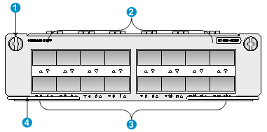
HIM-16GBP
The HIM-16GBP high-speed Layer 3 GE interface module provides 16 SFP ports. These SFP ports support Layer 3 routing.
Front panel
Figure 20 Front panel
|
(1) Captive screw |
(2) SFP ports |
|
(3) SFP port LEDs |
(4) Ejector lever |
LED
Table 29 SFP port LED description
|
Status |
Description |
|
Off |
No link is present. |
|
Steady green |
A 1000 Mbps link is present. |
|
Flashing green |
Data is being transmitted and received at 1000 Mbps. |
|
Steady yellow |
A 100 Mbps link is present. |
|
Flashing yellow |
Data is being transmitted and received at 100 Mbps. |
Interface specifications
Table 30 SFP port specifications
|
Item |
Specification |
|||||
|
Transceiver module type |
SFP |
|||||
|
Connector type |
LC |
|||||
|
Number of interfaces |
16 |
|||||
|
Interface standards |
802.3, 802.3u, 802.3ab |
|||||
|
Supported frame format |
· Ethernet_II · Ethernet_SNAP |
|||||
|
Optical transmit power |
Type |
Short-distance, multi-mode |
Medium-distance, single-mode |
Long-distance, single-mode |
Long-distance, single-mode |
Ultra-long distance, single-mode |
|
Min. |
–9.5 dBm |
–9 dBm |
–2 dBm |
–4 dBm |
–4 dBm |
|
|
Max. |
0 dBm |
–3 dBm |
5 dBm |
1 dBm |
2 dBm |
|
|
Receiving sensitivity |
–17 dBm |
–20 dBm |
–23 dBm |
–21 dBm |
–22 dBm |
|
|
Central wavelength |
850 nm |
1310 nm |
1310 nm |
1550 nm |
1550 nm |
|
|
Max. transmission distance |
0.55 km (0.34 miles) |
10 km (6.21 miles) |
40 km (24.86 miles) |
40 km (24.86 miles) |
70 km (43.50 miles) |
|
|
Fiber type |
62.5/125 μm multi-mode |
9/125 μm single-mode |
9/125 μm single-mode |
9/125 μm single-mode |
9/125 μm single-mode |
|
|
Transmission rate |
1000 Mbps, full duplex |
|||||
The following transceiver modules are available for the HIM-16GBP interface module:
· 100 Mbps fiber SFP transceiver modules.
· 1000 Mbps fiber SFP transceiver modules.
· 1000/100 Mbps fiber SFP transceiver modules.
· 10/100/1000 Mbps copper SFP transceiver modules (10/100/1000 Mbps autosensing is supported when the HIM-16GBP interface module uses this type of transceiver module.)
Prepare the transceiver modules yourself as required.
|
|
NOTE: Use only H3C transceiver modules for the router. Transceiver modules from other vendors might be incompatible with the router. The router reports an alarm when a non-H3C transceiver module is installed. |
Interface cables
Use interface cables for the HIM-16GBP transceiver module as follows:
· Fiber SFP transceiver module—Fiber that uses an LC connector.
· Copper SFP transceiver module—Category-5 straight-through or crossover twisted pair cable when the port is operating at 10/100 Mbps and Category-6 twisted pair cable when the port is operating at 1000 Mbps.
For the appearance and connection of the interface cables, see "Connecting an Ethernet interface cable" and "Connecting an optical interface cable."
HIM-2EXP
The HIM-2EXP 10-GE interface module provides two SFP+ ports. It is half the height of a typical HIM, and occupies one slot on a FIP.
Front panel
Figure 21 Front panel
|
(1) Captive screw |
(2) Ejector lever |
|
(3) SFP+ port LED (LINK/ACT) |
(4) SFP+ port |
LEDs
Table 31 SFP+ port LED description
|
Status |
Description |
|
Off |
No link is present. |
|
Steady green |
A link is present but no data is being transmitted or received. |
|
Flashing green |
A link is present and data is being transmitted and received. |
|
Steady yellow |
The transceiver module has failed to be detected. |
Interface specifications
Table 32 SFP+ port specifications
|
Item |
Specification |
|||
|
Transceiver module type |
SFP+ |
|||
|
Connector type |
LC |
|||
|
Number of interfaces |
2 |
|||
|
Supported physical layer type |
· LAN PHY—10GBASE-R · WAN PHY—10GBASE-W |
|||
|
Interface rate |
· LAN PHY—10.3125 Gbps · WAN PHY—9.95328 Gbps |
|||
|
Optical transmit power |
Type |
Short-distance, multi-mode |
Medium-distance, single-mode |
Long-distance, single-mode |
|
Min. |
–7.3 dBm |
–8.2 dBm |
–1 dBm |
|
|
Max. |
–1.08 dBm |
0.5 dBm |
2 dBm |
|
|
Receiving sensitivity |
–7.5 dBm |
–10.3 dBm |
–11.3 dBm |
|
|
Central wavelength |
850 nm |
1310 nm |
1550 nm |
|
|
Max transmission distance |
300 m (984.25 ft) |
10 km (6.21 miles) |
40 km (24.86 miles) |
|
|
Fiber type |
62.5/125 μm multi-mode |
9/125 μm single-mode |
9/125 μm single-mode |
|
Interface cables
Use an SFP+ transceiver module and an optical fiber that has an LC connector to connect the SFP+ port on the HIM-2EXP interface module.
For the appearance and connection of the interface cables, see "Connecting an optical interface cable."
MIMs
MIM-2GBE (RT-MIM-2GBE-H3)
The MIM-2GBE is a 2-port 10/100/1000M Base-T copper port (RJ-45) module. The MIM-2GBE is designed for router-LAN communication.
Front panel

|
(1) GE port |
(2) GE port link LED (LINK) |
|
(3) Captive screw |
(4) GE port active LED (ACT) |
LEDs
Table 33 LED description
|
LED |
Status |
Description |
|
LINK |
Off |
No link is present. |
|
On |
A link is present. |
|
|
ACT |
Off |
No data is being received or transmitted. |
|
Flashing |
Data is being received or transmitted. |
Interface specifications
Table 34 Interface specifications
|
Item |
Specification |
|
|
Connector type |
RJ-45 |
|
|
Number of interfaces |
2 |
|
|
Interface standards |
802.3, 802.3u, 802.3ab |
|
|
Interface type |
Auto MDI/MDI-X |
|
|
Supported frame format |
· Ethernet_II · Ethernet_SNAP |
|
|
Transmission distance |
100 m (328.08 ft) |
|
|
Interface speed and duplex mode |
10 Mbps |
Full/half duplex, auto-negotiation |
|
100 Mbps |
Full/half duplex, auto-negotiation |
|
|
1000 Mbps |
Full duplex |
|
|
|
NOTE: · The MDI standard is typically used on the Ethernet interface of network adapters; the MDI-X standard is typically used on hubs or LAN switches. · When 10/100 Mbps and half duplex/full duplex are specified for an Ethernet copper port, the Ethernet copper port operates in forced mode. When 1000 Mbps is specified or the interface speed and the duplex mode are not simultaneously specified for an Ethernet copper port, the port operates in auto-negotiation mode. · An Ethernet copper port supports auto MDI/MDI-X in both forced or auto-negotiation mode. |
Interface cables
A MIM-2GBE uses a category-5 straight-through or crossover Ethernet cable when operating at 10/100 Mbps and uses a category-6 cable (recommended) when operating at 1000 Mbps. For the appearance and connection of a MIM-2GBE interface cable, see "Connecting an Ethernet interface cable."
MIM-8E1(75)(RT-MIM-8E1(75)-H3)/MIM-8E1(75)-F(RT-MIM-8E1(75)-F-H3)
The MIM-8E1(75) is an 8-port channelized E1 interface module, which transmits, receives, and processes eight channels of E1 data, and supports CE1 access.
The MIM-8E1(75)-F is an 8-port non-channelized E1 interface module. It differs from the MIM-8E1(75) in these ways:
· The FE1 operating mode supported by the MIM-8E1(75)-F allows only one n × 64 kbps bundle to be formed on each interface, where n = 1 to 31.
· The MIM-8E1(75) allows arbitrary grouping of 31 channels and thereby multiple bundles.
Front panels
Figure 23 Front panel of MIM-8E1(75)
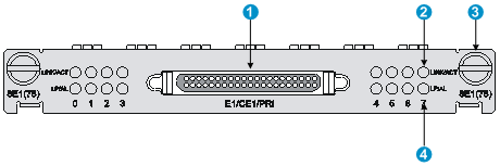
|
(1) DB-68 connector |
(2) Carrier signal LED (LINK/ACT) |
|
(3) Captive screw |
(4) Loopback/alarm LED (LP/AL) |
Figure 24 Front panel of MIM-8E1(75)-F
The front panel of MIM-8E1(75)-F is similar to that of MIM-8E1(75).
LEDs
|
LED |
Status |
Description |
|
LINK/ACT (Green) |
Off |
No carrier signals are being received. |
|
On |
Carrier signals are being received. |
|
|
Flashing |
Data is being transmitted or received. |
|
|
LP/AL (Yellow) |
Off |
No loopback or alarms have occurred. |
|
On |
The interface is in loopback state. |
|
|
Flashing |
A minimum of one alarm of the type of AIS, LFA, or RAI has occurred. |
Interface specifications
Table 36 Interface specifications
|
Item |
Specification |
|
Connector type |
DB-68 |
|
Number of interfaces |
1 |
|
Interface standard |
G.703 |
|
Interface speed |
2.048 Mbps |
|
Interface cable type |
75-ohm 8E1 splitter cable |
|
Cable characteristic impedance |
75 ohm |
|
Working modes |
E1, CE1, and FE1 (supported by the MIM-8E1(75)-F only) |
|
Services supported |
· Backup · Terminal access service |
Interface cables
The MIM-8E1(75) or MIM-8E1(75)-F provides eight E1 ports and uses a 75-ohm splitter cable. At one end of this 16-core coaxial cable is a DB-68 connector used to connect to the device, and at the other end are 16 BNC connectors used to connect to the peer devices.
|
|
NOTE: · The MIM-8E1(75)/MIM-8E1(75)-F does not support ISDN PRI. · For the MIM-8E1(75), if you use the timeslot binding command on the controller E1 interface, the system automatically creates a serial interface, on which the configuration takes effect. The MIM-8E1(75)-F does not have any controller E1 interfaces, and a physical interface corresponds to one and only one serial interface, which is automatically created without the need of additional configuration. · For the appearance and connection of a MIM-8E1(75)/MIM-8E1(75)-F interface cable, see "Connecting an E1 interface cable." |
MIM-8T1/MIM-8T1-F RT-MIM-8T1-H3)/MIM-8T1-F (RT-MIM-8T1-F-H3)
The MIM-8T1 is an 8-port channelized T1 interface module, which transmits, receives, and processes eight channels of T1 data, and supports CT1 access.
The MIM-8T1-F is an 8-port non-channelized T1 interface module. It differs from the MIM-8T1 in these ways:
· The FT1 operating mode supported by the MIM-8T1-F allows only one n × 64 kbps OR 56 kbps bundle to be formed on each interface, where n is in the range 1 to 24.
· The MIM-8T1 allows arbitrary grouping of 24 channels and thereby multiple bundles.
Front panels
Figure 25 Front panel of MIM-8T1
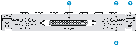
|
(1) DB-68 connector |
(2) Carrier signal LED (LINK/ACT) |
|
(3) Captive screw |
(4) Loopback/Alarm LED (LP/AL) |
Figure 26 Front panel of MIM-8T1-F
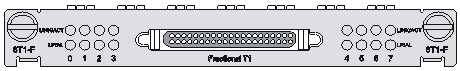
The front panel of the MIM-8T1-F is similar to that of the MIM-8T1.
Interface specifications
Table 37 Interface specifications
|
Item |
Specification |
|
Connector type |
RJ-45 |
|
Number of interfaces |
1 |
|
Interface standard |
· G.703/T1 102 · G.704 · AT&T TR 54016 · AT&T TR 62411 · ANSI T1.403 |
|
Interface speed |
1.544 Mbps |
|
Interface cable type |
8T1 splitter cable |
|
Working modes |
· CT1 (supported by the MIM-8T1) · FT1 (supported by the MIM-8T1-F) |
|
Services supported |
· Backup · Terminal access service |
LEDs
|
LED |
Status |
Description |
|
LINK/ACT (Green) |
Off |
No carrier signals are being received. |
|
On |
Carrier signals are being received. |
|
|
Flashing |
Data is being transmitted or received. |
|
|
LP/AL (Yellow) |
Off |
No loopback or alarms occur. |
|
On |
The interface is in loopback state. |
|
|
Flashing |
A minimum of one alarm of the type of AIS, LFA, or RAI occurs. |
Interface cables
The MIM-8T1 or MIM-8T1-F provides eight T1 interfaces and uses an 8T1 splitter cable. At one end of this cable is a DB-68 connector used to connect to the device, and at the other end are eight RJ-45 connectors used to connect to the peer devices.
|
|
NOTE: · The MIM-8T1/MIM-8T1-F does not support ISDN PRI. · For the MIM-8T1, if you use the timeslot binding command on the controller T1 interface, the system automatically creates the corresponding serial interface, on which you can make configurations. The MIM-8T1-F does not have a controller T1 interface, and a physical interface corresponds to one and only one serial interface, which is automatically created without the need of additional configuration. · For the appearance and connection of a MIM-8T1/MIM-8T1-F interface cable, see "Connecting a T1 interface cable." |
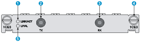
MIM-1CE3(RT-MIM-1CE3-V2-H3)
The MIM-1CE3 is a 1-port channelized E3 interface module. It has the following features:
· In E3 mode, it transceives and processes high-speed data streams over the E3 channel, and provides access to E3 data streams.
· In CE3 mode, it provides the low-speed access service at N × 64 kbps, where N is smaller than or equal to 128.
|
|
NOTE: · E3 represents the tertiary group rate of the E series in the TDM system, which is 34.368 Mbps. · An E3 channel can be channelized into 16 E1 channels through the demultiplex processes of E23 and E12, with each E1 channel supporting both the E1 and CE1 operating modes. E23 indicates either E2-to-E3 multiplex or E3-to-E2 demultiplex, and E12 indicates E1-to-E2 multiplex or E2-to-E1 demultiplex. E23 and E12 discussed here represent the demultiplex process. |
Front panel
|
(1) Carrier signal LED (LINK/ACT) |
(2) TX interface |
|
(3) RX interface |
(4) Captive screw |
|
(5) Loopback/Alarm LED (LP/AL) |
|
LEDs
|
LED |
Status |
Description |
|
LINK/ACT |
Off |
No carrier signals are received. |
|
On |
Carrier signals are received. |
|
|
Flashing |
Data is being transmitted or received. |
|
|
LP/AL |
Off |
No loopback or alarms occur. |
|
On |
The interface is in loopback state. |
|
|
Flashing |
A minimum of one alarm of the type of AIS, LFA, or RAI has occurred. · LFA—Loss of frame alignment. · AIS—Alarm indication signal. · RAI—Remote alarm indication. |
Interface specifications
Table 40 Interface specifications
|
Item |
Specification |
|
Connector type |
SMB |
|
Number of interfaces |
2 |
|
Interface standards |
G. 703, G.704, G.751 |
|
Interface speed |
34.368 Mbps |
|
Cable type |
75-ohm E3 coaxial cable |
|
Working modes |
E3/CE3 |
|
Services supported |
E3 leased line |
Interface cables
The MIM-1CE3 provides two SMB interfaces, with one interface acting as the transmission end (Tx) and the other as the receiving end (Rx). The Tx and Rx interfaces operate in the 75-ohm unbalanced transmission mode and thereby need a pair of 75-ohm unbalanced coaxial cables in use for connection with the peer device.
|
|
NOTE: · The MIM-1CE3 and MIM-1CT3 use the same type of E3/T3 cable. · The E3/T3 cable is an optional accessory for the MIM-1CE3 to be separately ordered if needed. · For the appearance and connection of an E3/T3 cable, see "Connecting a CE3/CT3 interface cable. " |
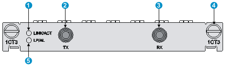
MIM-1CT3 (RT-MIM-1CT3-V2-H3)
The MIM-1CT3 is a 1-port channelized T3 interface module. It has the following features:
· In T3 mode, it transceives and processes high-speed data streams over the T3 channel, and provides access to T3 data streams.
· In CT3 mode, it provides the low-speed accessing service at N × 64 or N × 56 kbps, where N is smaller than or equal to 128.
|
|
NOTE: · T3 represents the tertiary group rate of the T series in the TDM system, which is 44.736 Mbps. · A T3 channel can be channelized into 28 T1 channels through the demultiplex processes of T23 and T12, with each T1 channel supporting both the T1 and CT1 operating modes. T23 indicates either T2-to-T3 multiplex or T3-to-T2 demultiplex, and T12 indicates T1-to-T2 multiplex or T2-to-T1 demultiplex. T23 and T12 discussed here represent the demultiplex process. |
Front panel
|
(1) Carrier signal LED (LINK/ACT) |
(2) TX interface |
|
(3) RX interface |
(4) Captive screw |
|
(5) Loopback/alarm LED (LP/AL) |
|
LEDs
|
LED |
Status |
Description |
|
LINK/ACT |
Off |
No carrier signals are being received. |
|
On |
Carrier signals are being received. |
|
|
Flashing |
Data is being transmitted or received. |
|
|
LP/AL |
Off |
No loopback or alarms occur. |
|
On |
The interface is in loopback state. |
|
|
Flashing |
A minimum of one alarm of the type of AIS, LFA, or RAI has occurred. · LFA—Loss of frame alignment. · AIS—Alarm indication signal. · RAI—Remote alarm indication. |
Interface specifications
Table 42 Interface specifications
|
Item |
Specification |
|
Connector type |
SMB |
|
Number of interfaces |
2 |
|
Interface standards |
· G.703 · G.704 · G.752 · AT&T TR 54014 · AT&T TR 62415 · ANSI T1.107 |
|
Interface speed |
44.736 Mbps |
|
Cable type |
75-ohm T3 coaxial cable |
|
Working modes |
T3/CT3 |
|
Services supported |
T3 leased line |
Interface cables
The MIM-1CE3 provides two SMB interfaces, with one interface acting as the transmission end (Tx) and the other as the receiving end (Rx). The Tx and Rx interfaces operate in the 75-ohm unbalanced transmission mode and thereby need a pair of 75-ohm unbalanced coaxial cables in use for connection with the peer device.
|
|
NOTE: · The MIM-1CT3 and MIM-1CE3 use the same type of E3/T3 cable. · The E3/T3 cable is an optional accessory for the MIM-1CE3 to be separately ordered if needed. · For the appearance and connection of an E3/T3 cable, see Connecting a CE3/CT3 interface cable. |
MIM-2SAE (RT-MIM-2SAE-H3)/MIM-4SAE (RT-MIM-4SAE-H3)/MIM-8SAE (RT-MIM-8SAE-H3)
The MIM-2SAE, MIM-4SAE, and MIM-8SAE are 2/4/8-port enhanced synchronous/asynchronous serial interface modules.
The MIM-2SAE/MIM-4SAE/MIM-8SAE only works in synchronous mode to receive, send and process the synchronous serial data. The MIM-2SAE/MIM-4SAE/MIM-8SAE supports the DTE/DCE mode.
Front panels
Figure 29 Front panel of MIM-2SAE

|
(1) Serial interface |
(2) Serial interface LINK LED |
|
(3) Captive screw |
(4) Serial interface ACT LED |
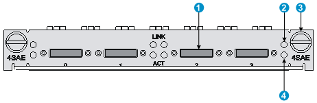
Figure 30 Front panel of MIM-4SAE
|
(1) Serial interface |
(2) Serial interface LINK LED |
|
(3) Captive screw |
(4) Serial interface ACT LED |
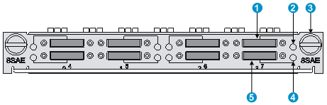
Figure 31 Front panel of MIM-8SAE
|
(1) Serial interface (7) |
(2) Serial interface 7 LINK/ACT LED |
|
(3) Captive screw |
(4) Serial interface 3 LINK/ACT LED |
|
(5) Serial interface (3) |
|
LEDs
· A LINK LED and an ACT LED are provided for each channel of the MIM-2SAE/MIM-4SAE.
· The MIM-8SAE provides only one LED for each channel.
Table 43 MIM-2SAE/MIM-4SAE LED description
|
LED |
Status |
Description |
|
LINK |
Off |
No link is present. |
|
On |
A link is present. |
|
|
ACT |
Off |
No data is being received or transmitted. |
|
Flashing |
Data is being received or transmitted. |
Table 44 MIM-8SAE LED description
|
LED status |
Description |
|
On |
A link is present. |
|
Flashing |
Data is being received or transmitted. |
Interface specifications
Table 45 Interface specifications
|
Item |
Specification (in synchronous mode) |
|
|
Connector type |
DB-28 |
|
|
Number of interfaces |
· MIM-2SAE: 2 · MIM-4SAE: 4 · MIM-8SAE: 8 |
|
|
Interface standard and working mode |
V.24 |
V.35, RS-449, X.21, RS-530 |
|
DTE, DCE |
DTE, DCE |
|
|
Minimum baud rate |
1200 bps |
1200 bps |
|
Max. baud rate |
64 Kbps |
2.048 Mbps |
|
Cable type |
· V.24 (RS-232) DTE cable · V.24 (RS-232) DCE cable · V.35 DTE cable · V.35 DCE cable · X.21 DTE cable · X.21 DCE cable · RS-449 DTE cable · RS-449 DCE cable · RS-530 DTE cable · RS-530 DCE cable |
|
|
Services supported |
DDN leased line |
|
Interface cables
Each interface on the MIM-2SAE/MIM-4SAE/MIM-8SAE is a 28-pin connector, and the interface cables for the MIM-2SAE/MIM-4SAE/MIM-8SAE are synchronous/asynchronous serial interface cables with DB-28 connectors.
Before connecting cables to the interfaces on the MIM-2SAE/MIM-4SAE/MIM-8SAE, examine the line properties. The following are cable options depending on different line properties:
· V.24 (RS-232) DTE cable—DB-25 (male) connector at the network end
· V.24 (RS-232) DCE cable—DB-25 (female) connector at the network end
· V.35 DTE cable—34-pin (male) connector at the network end
· V.35 DCE cable—34-pin (female) connector at the network end
· X.21 DTE cable—DB-15 (male) connector at the network end
· X.21 DCE cable—DB-15 (female) connector at the network end
· RS-449 DTE cable— DB-37 (male) connector at the network end
· RS-449 DCE cable—DB-37 (female) connector at the network end
· RS-530 DTE cable—DB-25 (male) connector at the network end
· RS-530 DCE cable—DB-25 (female) connector at the network end
|
|
NOTE: · The above cables are all optional for the MIM-2SAE/MIM-4SAE/MIM-8SAE to be separately ordered if needed. · All the above cables have a DB-28 connector at one end for connection with the router, and different types of connectors at the other end depending on the interface on the network side. · For the appearance and connection of a MIM-2SAE/MIM-4SAE/MIM-8SAE interface cable, see "Connecting a serial interface cable." |
SAPs
SAPs are not carried on the flexible interface platform (FIP) but inserted in the LPU slots of the router.
SAP-48GBE (RT-SAP-48GBE-H3)
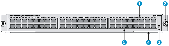
The SAP-48GBE is a 10Base-T/100Base-TX/1000Base-T auto-sensing Ethernet service module developed by H3C. The SAP-48GBE provides 48 RJ-45 interfaces, all of which feature Layer 3 routing and high-performance Layer 2 switching. Each interface uses a bi-color LED indicating the running status of the interface. In addition, the SAP-48GBE uses a run LED (RUN) to show the running status of the service module.
Front panel
|
(1) GE port status LED |
(2) Captive screw |
|
(3) System status LED (RUN) |
(4) Ejector lever |
|
(5) GE port |
|
Specifications
Table 46 Specifications
|
Item |
Specification |
|
Processor |
Multi-core MIPS processor with ASIC chips |
|
Flash |
4 MB |
|
Memory type and size |
· DDR2 SDRAM · 2 GB (default, two 1 GB memories)
Use two DDR2 SDRAM with the same size at a time. |
|
NVRAM |
128 KB |
|
Max. power consumption |
· Tested—162 W · Theoretical—200 W |
|
|
NOTE: The theoretical max power consumption, greater than the tested max power consumption, is the upper power consumption threshold defined for the SAP to prevent power module overloading. You must use the theoretical max power consumption, rather than the tested max power consumption, to calculate the total power consumption for managing power modules and determining power module numbers. |
LEDs
Table 47 LED description
|
LED |
Status |
Description |
|
RUN (Green) |
Off |
No power input is available or the SAP-48GBE has failed. |
|
Slow flashing (1 Hz) |
The SAP-48GBE is operating correctly. |
|
|
Fast flashing (8 Hz) |
System software image is being loaded (in this case, never power off the device or hot-swap the SAP-48GBE; otherwise, the SAP-48GBE might be damaged). |
|
|
GE 0 to GE 47 (Yellow/green) |
Off |
No link is present or the cable is faulty. |
|
Steady green |
A 1000 Mbps link is present |
|
|
Flashing green |
Data is being received or transmitted at 1000 Mbps. |
|
|
Steady yellow |
A 10/100 Mbps link is present. |
|
|
Flashing yellow |
Data is being received or transmitted at 10/100 Mbps. |
Interface specifications
Table 48 Interface specifications
|
Item |
Specification |
|
|
Connector type |
RJ-45 |
|
|
Number of interfaces |
48 |
|
|
Interface standards |
802.3, 802.3u, and 802.3ab |
|
|
Interface type |
Auto MDI/MDI-X |
|
|
Cable type |
Straight-through/crossover Ethernet cable |
|
|
Transmission distance |
100 m (328.08 ft) |
|
|
Supported frame format |
· Ethernet_II · Ethernet_SNAP |
|
|
Interface speed and duplex mode |
10 Mbps |
Full/half duplex, auto-negotiation |
|
100 Mbps |
Full/half duplex, auto-negotiation |
|
|
1000 Mbps |
Full duplex |
|
Interface cables
The SAP-48GBE uses a category-5 straight-through or crossover Ethernet cable when operating at 10/100 Mbps, and uses a category-6 cable (recommended) when operating at 1000 Mbps. For the appearance and connection of a SAP-48GBE interface cable, see "Connecting an Ethernet interface cable."
SAP-24GBP (RT-SAP-24GBP-H3)
The SAP-24GBP is a 24-port 100/1000 Mbps auto-sensing optical Ethernet service module. It provides 24 SFP ports, all of which feature Layer 3 routing and high-performance Layer 2 switching. Each interface uses a bi-color LED indicating the running status of the interface. In addition, the SAP-24GBP uses a run LED (RUN) to show the running status of the service module.
Front panels
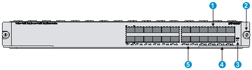
|
(1) SFP port |
(2) Captive screw |
|
(3) System status LED (RUN) |
(4) Ejector lever |
|
(5) SFP port status LED |
|
Specifications
Table 49 Specifications
|
Item |
Specification |
|
Processor |
Multi-core MIPS processor with ASIC chips |
|
Flash |
4 MB |
|
Memory type and size |
· DDR2 SDRAM · 2 GB (default, two 1 GB memory modules)
Use two DDR2 SDRAM modules of the same size at a time. |
|
NVRAM |
128 KB |
|
Max power consumption |
· Tested—125 W · Theoretical—150 W |
|
|
NOTE: The theoretical max power consumption, greater than the tested max power consumption, is the upper power consumption threshold defined for the SAP to prevent power module overloading. You must use the theoretical max power consumption, rather than the tested max power consumption, to calculate the total power consumption for managing power modules and determining power module numbers. |
LEDs
Table 50 LED description
|
LED |
Status |
Description |
|
RUN (Green) |
Off |
No power input is available or the SAP-24GBP has failed. |
|
Slow flashing (1 Hz) |
The SAP-24GBP is operating correctly. |
|
|
Fast flashing (8 Hz) |
System software image is being loaded (in this case, never power off the device or hot-swap the SAP-24GBP; otherwise, the SAP-24GBP might be damaged). |
|
|
SFP 0 to SFP 23 (Yellow/green) |
Off |
No link is present or the cable is faulty. |
|
Steady green |
A 1000 Mbps link is present |
|
|
Flashing green |
Data is being received or transmitted at 1000 Mbps. |
|
|
Steady yellow |
A 100 Mbps link is present. |
|
|
Flashing yellow |
Data is being received or transmitted at 100 Mbps. |
Interface specifications
Table 51 Interface specifications
|
Item |
Specification |
|||||
|
Connector type |
SFP |
|||||
|
Number of interfaces |
24 |
|||||
|
Interface standards |
802.3, 802.3u, and 802.3ab |
|||||
|
Supported frame format |
· Ethernet_II · Ethernet_SNAP |
|||||
|
Optical transmit power |
Type |
Short distance |
Medium distance |
Long distance |
Long distance |
Ultra-long distance |
|
Min. |
–9.5 dBm |
–9 dBm |
–2 dBm |
–4 dBm |
–4 dBm |
|
|
Max. |
0 dBm |
–3 dBm |
5 dBm |
1 dBm |
2 dBm |
|
|
Receiving sensitivity |
–17 dBm |
–20 dBm |
–23 dBm |
–21 dBm |
–22 dBm |
|
|
Central wavelength |
850 nm |
1310 nm |
1310 nm |
1550 nm |
1550 nm |
|
|
Fiber type |
62.5/125 μm multi-mode fiber |
9/125 μm single-mode fiber |
9/125 μm single-mode fiber |
9/125 μm single-mode fiber |
9/125 μm single-mode fiber |
|
|
Max. transmission distance |
0.55 km (0.3418 miles) |
10 km (6.21 miles) |
40 km (24.86 miles) |
40 km (24.86 miles) |
70 km (43.50 miles) |
|
|
Interface speed |
· 1000 Mbps (recommended) · Full duplex |
|||||
The SAP-24GBP supports the following types of transceiver modules:
· 100 Mbps SFP transceiver modules
· 1000 Mbps SFP transceiver modules
· 100/1000 Mbps SFP transceiver modules
· 10/100/1000 Mbps SFP copper transceiver modules supporting fiber-to-copper conversion (The SAP-24GBP supports 10/100/1000 Mbps auto-sensing if used together with a transceiver module.)
The SAP-24GBP is optional to be separately ordered if needed.
Use transceiver modules provided by H3C only. The device might be incompatible with other transceiver modules.
Interface cables
· When working with SFP transceiver modules, the SAP-24GBP must use an optical fiber with LC-type connectors.
· When working with transceiver modules supporting fiber-to-copper conversion, the SAP-24GBP uses category-5 straight-through or crossover Ethernet cables when operating at 10/100 Mbps, and uses category-6 cable (recommended) when operating at 1000 Mbps.
For the appearance and connection of a SAP-24GBP interface cable, see "Connecting an Ethernet interface cable" or "Connecting an optical interface cable."
SAP-48GBP (RT-SAP-48GBP-H3)
The SAP-48GBP is a 48-port 100/1000 Mbps auto-sensing optical Ethernet service module. It provides 48 SFP ports, all of which feature Layer 3 routing and high-performance Layer 2 switching. Each port uses a bi-color LED indicating the running status of the port. In addition, the SAP-48GBP uses a run LED (RUN) to show the running status of the module.
Front panel
Figure 34 Front panel
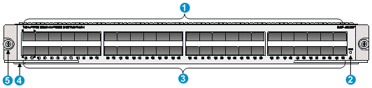
|
(1) SFP port |
(2) System status LED (RUN) |
|
(3) SFP status LED |
(4) Ejector lever |
|
(5) Captive screw |
|
Specifications
Table 52 Specifications
|
Item |
Specification |
|
Flash |
4 MB |
|
Memory type and size |
· DDR2 SDRAM · 2 GB (default, two 1 GB memory modules)
Use two DDR2 SDRAM modules of the same size at a time. |
|
NVRAM |
128 KB |
|
Max power consumption |
· Tested—132 W · Theoretical—200 W |
|
|
NOTE: The theoretical max power consumption, greater than the tested max power consumption, is the upper power consumption threshold defined for the SAP to prevent power module overloading. You must use the theoretical max power consumption, rather than the tested max power consumption, to calculate the total power consumption for managing power modules and determining power module numbers. |
LEDs
Table 53 LED description
|
LED |
Status |
Description |
|
RUN (Green) |
Off |
No power input is available or the SAP-48GBP has failed. |
|
Slow flashing (1 Hz) |
The SAP-48GBP is operating correctly. |
|
|
Fast flashing (8 Hz) |
System software image is being loaded (in this case, never power off the device or hot-swap the SAP-48GBP; otherwise, the SAP-48GBP might be damaged). |
|
|
SFP 0 to SFP 47 (Yellow/green) |
Off |
No link is present or the cable is faulty. |
|
Steady green |
A 1000 Mbps link is present |
|
|
Flashing green |
Data is being received or transmitted at 1000 Mbps. |
|
|
Steady yellow |
A 100 Mbps link is present. |
|
|
Flashing yellow |
Data is being received or transmitted at 100 Mbps. |
Interface specifications
Table 54 Interface specifications
|
Item |
Specification |
|||||
|
Connector type |
SFP |
|||||
|
Number of interfaces |
48 |
|||||
|
Interface standards |
802.3, 802.3u, and 802.3ab |
|||||
|
Supported frame format |
· Ethernet_II · Ethernet_SNAP |
|||||
|
Optical transmit power |
Type |
Short distance |
Medium distance |
Long distance |
Long distance |
Ultra-long distance |
|
Min. |
–9.5 dBm |
–9 dBm |
–2 dBm |
–4 dBm |
–4 dBm |
|
|
Max. |
0 dBm |
–3 dBm |
5 dBm |
1 dBm |
2 dBm |
|
|
Receiving sensitivity |
–17 dBm |
–20 dBm |
–23 dBm |
–21 dBm |
–22 dBm |
|
|
Central wavelength |
850 nm |
1310 nm |
1310 nm |
1550 nm |
1550 nm |
|
|
Fiber type |
62.5/125 μm multi-mode fiber |
9/125 μm single-mode fiber |
9/125 μm single-mode fiber |
9/125 μm single-mode fiber |
9/125 μm single-mode fiber |
|
|
Max. transmission distance |
0.55 km (0.3418 miles) |
10 km (6.21 miles) |
40 km (24.86 miles) |
40 km (24.86 miles) |
70 km (43.50 miles) |
|
|
Interface speed |
· 1000 Mbps (recommended) · Full duplex |
|||||
The SAP-48GBP supports the following types of transceiver modules:
· 100 Mbps SFP transceiver modules
· 1000 Mbps SFP transceiver modules
· 100/1000 Mbps SFP transceiver modules
· 10/100/1000 Mbps SFP copper transceiver modules supporting fiber-to-copper conversion (The SAP-48GBP supports 10/100/1000 Mbps auto-sensing if used together with a transceiver module.)
The SAP-48GBP is optional to be separately ordered if needed.
Use transceiver modules provided by H3C only. The device might be incompatible with other transceiver modules and thus displays alarms automatically.
Interface cables
· When working with SFP transceiver modules, the SAP-48GBP must use an optical fiber with LC-type connectors.
· When working with transceiver modules supporting fiber-to-copper conversion, the SAP-48GBP uses category-5 straight-through or crossover Ethernet cables when operating at 10/100 Mbps, and uses category-6 cable (recommended) when operating at 1000 Mbps.
For the appearance and connection of a SAP-48GBP interface cable, see "Connecting an Ethernet interface cable" or "Connecting an optical interface cable."
SAP-4EXP (RT-SAP-4EXP-H3)
The SAP-4EXP is a 4-port 10 Gbps Ethernet service module. It provides 4 SFP+ ports, all of which feature Layer 3 routing and high-performance Layer 2 switching. Each port uses a bi-color LED indicating the running status of the interface. In addition, the SAP-4EXP uses a run LED (RUN) to show the running status of the module.
Front panel
Figure 35 Front panel
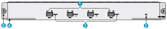
|
(1) SFP+ ports 0 to 3 |
(2) Status LED (RUN) |
|
(3) SFP+ port LEDs |
(4) Ejector lever |
|
(5) Captive screw |
|
Interface specifications
Table 55 Interface specifications
|
Item |
Remarks |
|
Flash |
8 MB |
|
Memory type and size |
DDR3 SDRAM · 4 GB (default, two 2-GB memory modules) · 4 GB (maximum, two 2-GB memory modules) Use two DDR3 SDRAM modules with the same size at a time. |
|
NVRAM |
128 KB |
|
Max power consumption |
· Tested—109 W · Theoretical—150 W |
|
|
NOTE: The theoretical max power consumption, greater than the tested max power consumption, is the upper power consumption threshold defined for the SAP to prevent power module overloading. You must use the theoretical max power consumption, rather than the tested max power consumption, to calculate the total power consumption for managing power modules and determining power module numbers. |
LEDs
Table 56 LED description
|
LED |
Status |
Description |
|
RUN (Green) |
Off |
No power input is available or the SAP-4EXP has failed. |
|
Slow flashing (1 Hz) |
The SAP-4EXP is operating correctly. |
|
|
Fast flashing (8 Hz) |
System software image is being loaded or the SAP-4EXP is not operating.
To avoid hardware damage, do not power off the router, or insert or remove the SAP-4EXP when the software image is being loaded. |
|
|
SFP+ 0 to SFP+ 3 (Yellow/green) |
Off |
No link is present. |
|
Steady green |
A 10 Gbps link is present. |
|
|
Flashing green |
Data is being received or transmitted at 10 Gbps. |
|
|
Steady yellow |
The transceiver module failed to be detected. |
Interface specifications
Table 57 10G Ethernet port specifications
|
Item |
Supported standard |
|
Protocol standard |
802.3ae |
|
Connector type |
LC |
|
Transceiver module |
SFP+ |
|
Physical layer type supported |
10GBASE-R/W |
|
Interface rate |
· In LAN PHY mode: 10.3125 Gbps · In WAN PHY mode: 9.95328 Gbps |
Table 58 Transceiver modules for the SAP-4EXP 10G Ethernet ports
|
Model |
Central wavelength |
Connector |
Optical fiber |
Max. transmission distance |
|
SFP-XG-SX-MM850-A |
850 nm |
LC |
50/125 μm multi-mode optical fiber |
300 m (984.25 ft) |
|
SFP-XG-LX-SM1310 |
1310 nm |
LC |
9/125 μm single-mode optical fiber |
10 km (6.21 miles) |
|
SFP-XG-LH40-SM1550 |
1550 nm |
LC |
9/125 μm single-mode optical fiber |
40 km (24.86 miles) |
Interface cables
The SAP-4EXP must use an optical fiber with LC-type connectors. For the appearance and connection of a SAP-4EXP interface cable, see "Connecting an optical interface cable."
SAP-20GE2XP
The SAP-20GE2XP provides 16 SFP ports, four combo interfaces, and two SFP+ ports. It provides a bi-color LED for each port to indicate the operating status of the port. It also provides a RUN LED to indicate the operating status of the module.
Front panel
Figure 36 Front panel
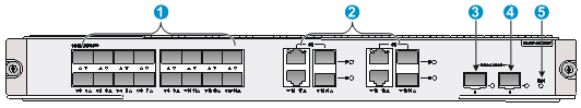
|
(1) SFP ports (GE0 to GE15) |
(2) Combo interfaces (GE16 to GE19) |
|
(3) SFP+ port 0 |
(4) SFP+ port 1 |
|
(5) Operating status LED (RUN) |
|
Specifications
Table 59 SAP-20GE2XP specifications
|
Item |
Specification |
|
Flash |
8 MB. |
|
Memory type and size |
· Default—Two 2-GB DDR3 SDRAMs. · Maximum—Four 2-GB DDR3 SDRAMs. |
|
NVRAM |
128 KB. |
|
SFP ports |
16 × SFP ports, 100/1000 Mbps auto-sensing. The following transceiver modules are available for the SFP ports: · 100 Mbps SFP transceiver modules. · 1000 Mbps SFP transceiver modules. · 100/1000 Mbps SFP transceiver modules. · SFP-T copper transceiver modules (The SFP port supports 10/100/1000 Mbps auto-sensing when used with this transceiver module.) |
|
Combo interfaces |
Four. · Copper port—Straight-through/crossover autosensing: ? 10/100 Mbps, half/full-duplex. ? 1000 Mbps, full-duplex. · Fiber port—1000 Mbps, full-duplex. |
|
10G SFP+ ports |
2. |
|
Hot swapping |
Supported. |
|
Max power consumption |
· Tested—128 W. · Theoretical—150 W. |
LEDs
Table 60 LED description
|
LED |
Status |
Description |
|
RUN (green) |
Off |
No power input is available or the SAP-20GE2XP has failed. |
|
Slow flashing (1 Hz) |
The SAP-20GE2XP is operating correctly. |
|
|
Fast flashing (8 Hz) |
System software is being loaded or the SAP-20GE2XP is not operating.
To avoid hardware damage, do not power off the router, or insert or remove the SAP-20GE2XP when the software image is being loaded. |
|
|
Status LEDs for SFP ports GE0 to GE15 (yellow/green) |
Off |
No link is present. |
|
Steady green |
A 1000 Mbps link is present. |
|
|
Flashing green |
Data is being received or transmitted at 1000 Mbps. |
|
|
Steady yellow |
A 100 Mbps link is present. |
|
|
Flashing yellow |
Data is being received or transmitted at 100 Mbps. |
|
|
Status LEDs for combo copper ports GE16 to GE 19 (yellow/green) |
Off |
No link is present. |
|
Steady green |
A 1000 Mbps link is present. |
|
|
Flashing green |
Data is being received or transmitted at 1000 Mbps. |
|
|
Steady yellow |
A 10/100 Mbps link is present. |
|
|
Flashing yellow |
Data is being received or transmitted at 10/100 Mbps. |
|
|
Status LEDs for combo fiber ports GE16 to GE 19 (yellow/green) |
Off |
No link is present. |
|
Steady green |
A 1000 Mbps link is present. |
|
|
Flashing green |
Data is being received or transmitted at 1000 Mbps. |
|
|
Steady yellow |
A 100 Mbps link is present. |
|
|
Flashing yellow |
Data is being received or transmitted at 100 Mbps. |
|
|
Status LEDs for SFP+ ports 0 and 1 (yellow/green) |
Off |
No link is present. |
|
Steady green |
A 10 Gbps link is present. |
|
|
Flashing green |
Data is being received or transmitted at 10 Gbps. |
|
|
Steady yellow |
The transceiver module failed to be detected. |
Interface specifications
Table 61 SFP port specifications
|
Item |
Specification |
|||||
|
Connector type |
LC |
|||||
|
Transceiver module type |
SFP |
|||||
|
Network synchronization |
Supported |
|||||
|
1588v2.2 protocol |
Supported |
|||||
|
Interface standards |
802.3, 802.3u, and 802.3ab |
|||||
|
Transmit power |
Type |
Short-distance, multi-mode (850 nm) |
Medium-distance, single-mode (1310 nm) |
Long-distance (1310 nm) |
Long-distance (1550 nm) |
Super long distance (1550 nm) |
|
Min. |
–9.5 dBm |
–9 dBm |
–2 dBm |
–4 dBm |
–4 dBm |
|
|
Max. |
0 dBm |
–3 dBm |
5 dBm |
1 dBm |
2 dBm |
|
|
Receive sensitivity |
–17 dBm |
–20 dBm |
–23 dBm |
–21 dBm |
–22 dBm |
|
|
Operating mode |
1000 Mbps, full duplex |
|||||
Table 62 Transceiver modules available for the SFP ports
|
Transceiver module model |
Central wavelength |
Connector |
Optical fiber |
Data rate |
Max transmission distance |
|
SFP-GE-SX-MM850-A |
850 nm |
LC |
62.5/125 μm, multi-mode |
1250 Mbps |
0.55 km (0.34 miles) |
|
SFP-GE-LX-SM1310-A |
1310 nm |
LC |
9/125 μm, single-mode |
1250 Mbps |
10 km (6.21 miles) |
|
SFP-GE-LH40-SM1310 |
1310 nm |
LC |
9/125 μm, single-mode |
1250 Mbps |
40 km (24.86 miles) |
|
SFP-GE-LH40-SM1550 |
1550 nm |
LC |
9/125 μm, single-mode |
1250 Mbps |
40 km (24.86 miles) |
|
SFP-GE-LH70-SM1550 |
1550 nm |
LC |
9/125 μm, single-mode |
1250 Mbps |
70 km (43.50 miles) |
Table 63 Combo copper port specifications
|
Item |
Specification |
|
|
Connector type |
RJ-45 |
|
|
Interface type |
Auto MDI/MDI |
|
|
Frame format supported |
· Ethernet_II · Ethernet_SNAP |
|
|
Interface speed and duplex mode |
10 Mbps auto-sensing |
Full/half duplex, auto-negotiation |
|
100 Mbps auto-sensing |
Full/half duplex, auto-negotiation |
|
|
1000 Mbps auto-sensing |
Full duplex, auto-negotiation |
|
For the combo fiber port specifications, see Table 61. For the transceiver module available for the combo fiber ports, see Table 62.
Table 64 SFP+ port specifications
|
Item |
Specification |
|||||
|
Connector type |
LC |
|||||
|
Transceiver module |
SFP+ |
|||||
|
Network synchronization |
Supported |
|||||
|
1588v2.2 protocol |
Supported |
|||||
|
Interface standards |
802.3ae |
|||||
|
Transmit power |
Type |
Short-distance, multi-mode (850 nm) |
Medium-distance, (1310 nm) |
Long-distance (1310 nm) |
Long-distance (1550 nm) |
Super long distance (1550 nm) |
|
Min. |
–7.3 dBm |
–6.5 dBm |
–8.2 dBm |
–4.7 dBm |
0 dBm |
|
|
Max. |
–1 dBm |
0.5 dBm |
0.5 dBm |
4 dBm |
4 dBm |
|
|
Receive sensitivity |
–7.5 dBm |
–6.5 dBm |
–10.3 dBm |
–11.3 dBm |
–24 dBm |
|
|
Central wavelength |
850 nm |
1310 nm |
1310 nm |
1550 nm |
1550 nm |
|
|
Fiber type |
50/125 μm and 62.5/125 μm multi-mode |
50/125 μm and 62.5/125 μm multi-mode |
9/125 μm single-mode |
9/125 μm single-mode |
9/125 μm single-mode |
|
|
Operating mode |
10 Gpbs, full duplex |
|||||
Table 65 Transceiver modules available for the SFP+ ports
|
Model |
Central wavelength |
Connector |
Optical fiber |
Max transmission distance |
|
SFP-XG-SX-MM850-A |
850 nm |
LC |
50/125 μm multi-mode optical fiber |
300 m (984.25 ft) |
|
SFP-XG-LX-SM1310 |
1310 nm |
LC |
9/125 μm single-mode optical fiber |
10 km (6.21 miles) |
|
SFP-XG-LH40-SM1550 |
1550 nm |
LC |
9/125 μm single-mode optical fiber |
40 km (24.86 miles) |
Table 66 SFP+ DAC cable available for the SFP+ ports
|
Model |
Length |
Data rate |
Remarks |
|
LSWM1STK |
0.65 m (2.13 ft) |
10.31 Gbps |
Used for connecting SFP+ ports |
|
LSWM2STK |
1.2 m (3.94 ft) |
||
|
LSWM3STK |
3 m (9.84 ft) |
||
|
LSTM1STK |
5 m (16.40 ft) |
|
|
NOTE: Use transceiver modules provided by H3C only. The router might be incompatible with other transceiver modules. |
Interface cables
Use the following cables for the SAP-20GE2XP ports:
· Fiber port—An SFP/SFP+ transceiver module and a fiber that has an LC connector.
· Combo copper port operating at 10/100 Mbps—Category-5 straight-through/crossover network cables.
· Combo fiber port operating at 1000 Mbps—Category-6 network cables.
For the appearance and connection methods of the interface cables, see "Connecting an Ethernet interface cable" and "Connecting an optical interface cable."
SAP-28GE
The SAP-28GE provides 16 SFP ports and 12 combo interfaces. It provides a bi-color LED for each port to indicate the operating status of the port. It also provides a RUN LED to indicate the operating status of the module.
Front panel
Figure 37 Front panel
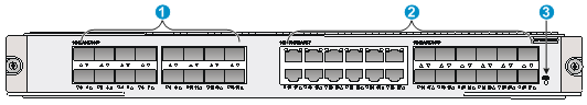
|
(1) SFP ports (GE0 to GE15) |
(2) Combo interfaces (GE16 to GE27) |
|
(3) Operating status LED (RUN) |
|
Specifications
Table 67 SAP-28GE specifications
|
Item |
Specification |
|
Flash |
8 MB. |
|
Memory type and size |
· Default—Two 2-GB DDR3 SDRAMs. · Maximum—Four 2-GB DDR3 SDRAMs. |
|
NVRAM |
128 KB. |
|
SFP ports |
16 × SFP ports, 100/1000 Mbps auto-sensing. The following transceiver modules are available for the SFP ports: · 100 Mbps SFP transceiver modules. · 1000 Mbps SFP transceiver modules. · 100/1000 Mbps SFP transceiver modules. · SFP-T copper transceiver modules (The SFP port supports 10/100/1000 Mbps auto-sensing when used with this transceiver module.) |
|
Combo interfaces |
12. · Copper port—Straight-through/crossover autosensing: ? 10/100 Mbps, half/full-duplex. ? 1000 Mbps, full-duplex. · Fiber port—1000 Mbps, full-duplex. |
|
Hot swapping |
Supported. |
|
Max power consumption |
· Tested—132 W. · Theoretical—150 W. |
LEDs
Table 68 LED description
|
LED |
Status |
Description |
|
RUN (green) |
Off |
No power input is available or the SAP-28GE has failed. |
|
Slow flashing (1 Hz) |
The SAP-28GE is operating correctly. |
|
|
Fast flashing (8 Hz) |
System software is being loaded or the SAP-28GE is not operating.
To avoid hardware damage, do not power off the router, or insert or remove the SAP-28GE when system software is being loaded. |
|
|
Status LEDs for SFP ports GE0 to GE15 (yellow/green) |
Off |
No link is present. |
|
Steady green |
A 1000 Mbps link is present. |
|
|
Flashing green |
Data is being received or transmitted at 1000 Mbps. |
|
|
Steady yellow |
A 100 Mbps link is present. |
|
|
Flashing yellow |
Data is being received or transmitted at 100 Mbps. |
|
|
Status LEDs for combo copper ports GE16 to GE27 (yellow/green) |
Off |
No link is present. |
|
Steady green |
A 1000 Mbps link is present. |
|
|
Flashing green |
Data is being received or transmitted at 1000 Mbps. |
|
|
Steady yellow |
A 10/100 Mbps link is present. |
|
|
Flashing yellow |
Data is being received or transmitted at 10/100 Mbps. |
|
|
Status LEDs for combo fiber ports GE16 to GE27 (yellow/green) |
Off |
No link is present. |
|
Steady green |
A 1000 Mbps link is present. |
|
|
Flashing green |
Data is being received or transmitted at 1000 Mbps. |
|
|
Steady yellow |
A 100 Mbps link is present. |
|
|
Flashing yellow |
Data is being received or transmitted at 100 Mbps. |
Interface specifications
Table 69 SFP port specifications
|
Item |
Specification |
|||||
|
Connector type |
LC |
|||||
|
Transceiver module type |
SFP |
|||||
|
Network synchronization |
Supported |
|||||
|
1588v2.2 protocol |
Supported |
|||||
|
Interface standards |
802.3, 802.3u, and 802.3ab |
|||||
|
Transmit power |
Type |
Short-distance, multi-mode (850 nm) |
Medium-distance, single-mode (1310 nm) |
Long-distance (1310 nm) |
Long-distance (1550 nm) |
Super long distance (1550 nm) |
|
Min. |
–9.5 dBm |
–9 dBm |
–2 dBm |
–4 dBm |
–4 dBm |
|
|
Max. |
0 dBm |
–3 dBm |
5 dBm |
1 dBm |
2 dBm |
|
|
Receive sensitivity |
–17 dBm |
–20 dBm |
–23 dBm |
–21 dBm |
–22 dBm |
|
|
Operating mode |
1000 Mbps, full duplex |
|||||
Table 70 Transceiver modules available for the SFP ports
|
Transceiver module model |
Central wavelength |
Connector |
Optical fiber |
Data rate |
Max transmission distance |
|
SFP-GE-SX-MM850-A |
850 nm |
LC |
62.5/125 μm, multi-mode |
1250 Mbps |
0.55 km (0.34 miles) |
|
SFP-GE-LX-SM1310-A |
1310 nm |
LC |
9/125 μm, single-mode |
1250 Mbps |
10 km (6.21 miles) |
|
SFP-GE-LH40-SM1310 |
1310 nm |
LC |
9/125 μm, single-mode |
1250 Mbps |
40 km (24.86 miles) |
|
SFP-GE-LH40-SM1550 |
1550 nm |
LC |
9/125 μm, single-mode |
1250 Mbps |
40 km (24.86 miles) |
|
SFP-GE-LH70-SM1550 |
1550 nm |
LC |
9/125 μm, single-mode |
1250 Mbps |
70 km (43.50 miles) |
Table 71 Combo copper port specifications
|
Item |
Specification |
|
|
Connector type |
RJ-45 |
|
|
Interface type |
Auto MDI/MDI-X |
|
|
Frame format supported |
· Ethernet_II · Ethernet_SNAP |
|
|
Interface speed and duplex mode |
10 Mbps auto-sensing |
Half/full duplex, auto-negotiation |
|
100 Mbps auto-sensing |
Half/full duplex, auto-negotiation |
|
|
1000 Mbps auto-sensing |
Full duplex, auto-negotiation |
|
For the combo fiber port specifications, see Table 69. For the transceiver module available for the combo fiber ports, see Table 70.
|
|
NOTE: Use transceiver modules provided by H3C only. The router might be incompatible with other transceiver modules. |
Interface cables
Use the following cables for the SAP-28GE ports:
· SFP port—An SFP transceiver module and a fiber that has an LC connector.
· Combo copper port operating at 10/100 Mbps—Category-5 straight-through/crossover network cables.
· Combo fiber port operating at 1000 Mbps—Category-6 network cables.
For the appearance and connection methods of the interface cables, see "Connecting an Ethernet interface cable" and "Connecting an optical interface cable."
Connecting an Ethernet interface cable
Appearance of an Ethernet cable
![]()
10/100 Mbps Ethernet uses category-5 twisted pair cables, while 1000 Mbps Ethernet uses category-5 enhanced or category-6 twisted pair cables. Twisted pair cables include straight-through cables and crossover cables.
Category-5 cables provide a transmission frequency of 100 MHz for voice and data transmission; they are mainly used in 100Base-T and 10Base-T networks. Category-5 cables are common Ethernet cables, which can also be used to transmit 1000 Mbps Ethernet data.
Category-5 enhanced cables feature low attenuation and crosstalk, providing higher attenuation to crosstalk ratio (ACR), less delay error and higher performance than category-5 cables. Category-5 enhanced cables are mainly used in 1000 Mbps Ethernet networks.
Category-6 cables provide a transmission frequency of 1 MHz to 250 MHz, and improve the performance on crosstalk and return loss. A fine better return loss performance is extremely important for new-generation full-duplex high-speed networks. Category-6 cables have sufficient power sum ACR (PS-ACR) when working at 200 MHz. They provide a bandwidth two times than that of category-5 enhanced cables, thus featuring a higher transmission performance. Therefore, category-6 cables are suitable for applications requiring a transmission speed of more than 1 Gbps.
The 10/100 Mbps Ethernet uses two pairs of cables, orange/white, orange, green/white and green cables, to transmit and receive data, while the 1000 Mbps Ethernet uses four pairs of cables to transmit and receive data.
For the pinouts of common twisted pair cables, see the following tables. (A and B represent the two ends of a cable.)
Table 72 Straight-through cable pinouts
|
Pinout No. |
A |
B |
|
1 |
Orange/white |
Orange/white |
|
2 |
Orange |
Orange |
|
3 |
Green/white |
Green/white |
|
4 |
Blue |
Blue |
|
5 |
Blue/white |
Blue/white |
|
6 |
Green |
Green |
|
7 |
Brown/white |
Brown/white |
|
8 |
Brown |
Brown |
Table 73 Crossover cable pinouts
|
Pinout No. |
A |
B |
|
1 |
Orange/white |
Green/white |
|
2 |
Orange |
Green |
|
3 |
Green/white |
Orange/white |
|
4 |
Blue |
Blue |
|
5 |
Blue/white |
Blue/white |
|
6 |
Green |
Orange |
|
7 |
Brown/white |
Brown/white |
|
8 |
Brown |
Brown |
|
|
NOTE: Strictly follow the pinouts in the above tables when identifying or making the two types of Ethernet cables; otherwise, the communication quality might be affected. |
Connecting an Ethernet cable
1. Connect one end of an Ethernet cable to an Ethernet port on the module and the other end to the Ethernet port on the peer device. Because the Ethernet port of the module supports MDI/MDIX auto-sensing, you can use a straight-through cable or crossover cable to connect the port.
2. Examine the status of the LED of the Ethernet port after power-on. For the status of the LED, see the relevant part in this manual.
Connecting an optical interface cable
Appearance of transceiver module, optical fiber and connector
Optical interfaces need to work with SFP, SFP+, XFP, or QSFP+ transceiver modules and optical fibers with LC-type connectors.
Figure 39 SFP transceiver module

Figure 40 SFP+ transceiver module
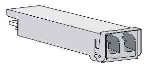
Figure 41 XFP transceiver module
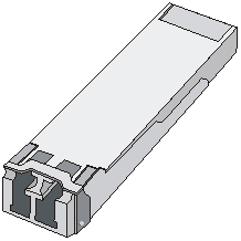
Figure 42 QSFP+ transceiver module
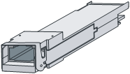
Figure 43 LC-type optical fiber connector
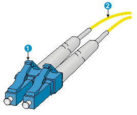
|
(1) LC-type optical fiber connector |
(2) Optical fiber |
Connecting an optical fiber
|
|
CAUTION: · Never stare into an open fiber Ethernet port, because invisible rays might be emitted from the port. · Cover the dust cover if no optical fiber connector is connected to the copper Ethernet port. |
To connect an optical fiber:
1. Insert the SFP/SFP+/XFP transceiver module to the SFP/SFP+/XFP port on the interface module or service module.
2. Identify the Rx and Tx ports on the transceiver. Plug the LC connector at one end of one fiber cable into the Rx port of the router and the LC connector at the other end into the Tx port of the peer device. Plug the LC connector at one end of another fiber cable into the Tx port of the router and the LC connector at the other end to the Rx port of the peer device.
3. View the LINK LED after connection.
? If the LED is on, the optical fiber link is present.
? If the LED is off, no link is present. This might be because the TX and Rx port of the optical fiber are not connected correctly. In this case, connect the optical fiber again.
Connecting an E1 interface cable
Appearance of the 4E1/8E1 splitter cable
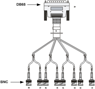
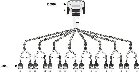
Connecting the cable
When connecting the interface cable, pay attention to the mark on the interface to avoid wrong insertion, which might damage the interface module or even the host.
H3C recommends that you install a special lightning arrester at the input end of its connection cable to obtain better lightning protection when the cable is led outdoors. For more information about lightning arrestor, see the installation guide.
To connect the 4E1/8E1 splitter cable:
1. Plug the DB-68 end of the 75-ohm 4E1/8E1 splitter cable to the DB-68 interface of the interface module and then fasten the screws.
2. Examine the sequence number on the BNC connector and Tx/Rx mark on the other end of the cable.
? If the 75-ohm 4E1/8E1 splitter cable need not be extended, you can connect the BNC connector of the cable to the peer device directly.
Figure 46 Connecting the 4E1/8E1 splitter cable (1)
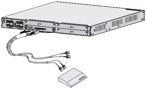
? If the 75-ohm 4E1/8E1 splitter cable need be extended, you can connect the BNC connector of the cable to the coaxial cable connector and connect the other end of the coaxial cable connector to the peer device through a 75-ohm E1 trunk cable.
Figure 47 Connecting the 4E1/8E1 splitter cable (2)
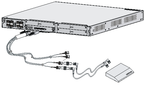
3. Examine the LINK LED after connection.
? If the LED is on, the optical fiber link is present.
? If the LED is off, a fault has occurred on the link and the signal is out of synchronization. In this case, examine the link.
|
|
NOTE: · The Tx end of the cable must be connected to the Rx end of the peer device, and the Rx end of the cable to the Tx end of the peer device. · The coaxial cable connector and 75-ohm E1 trunk cable are optional accessories to be separately ordered if needed. |
Connecting a T1 interface cable
Appearance of the 4T1/8T1 splitter cable
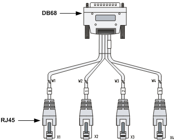
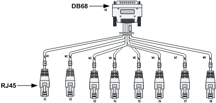
|
|
NOTE: · When connecting the interface cable, pay attention to the mark on the interface to avoid wrong insertion, which might damage the interface module or even the host. · H3C recommends that you install a special lightning arrester at the input end of its connection cable to obtain better lightning protection when the cable is led outdoors. For more information about lightning arrestor, see the installation guide. |
Connecting the cable
1. Plug the DB-68 end of the 4T1/8T1 splitter cable to the DB-68 interface of the MIM-8T1/MIM-8T1-F/MIM-IMA-4T1.
2. Plug the RJ-45 end of the 4T1/8T1 splitter cable to the peer device.
3. Examine the LINK LED on the MIM-8T1/MIM-8T1-F/MIM-IMA-4T1 after connection. If the LED is off, a fault has occurred on the link. In this case, examine the link.
Connecting a CE3/CT3 interface cable
Appearance of the E3/T3 cable
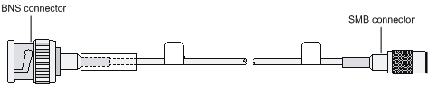
|
|
NOTE: H3C recommends that you install a special lightning arrester at the input end of its connection cable to obtain better lightning protection when the cable is led outdoors. For more information about lightning arrestor, see the installation guide. |
Connecting the cable
1. Connect the SMB connector of an E3/T3 cable to the Tx port on the interface module and another end to the Rx port on the device to be connected.
2. Connect the SMB connector of another E3/T3 cable to the Rx port of interface module and another end to the Tx port on the device to be connected.
3. Examine the LINK LED on the module panel. It is off when fault has occurred on the link and signal is out of synchronization. In this case, examine the link.
Connecting a serial interface cable
Appearance of the serial interface cable
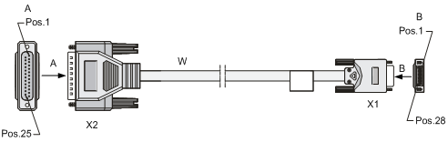
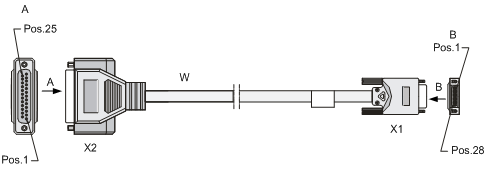
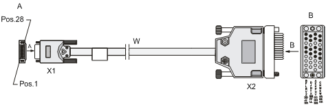
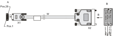
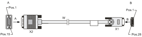
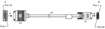
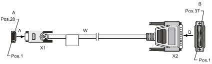
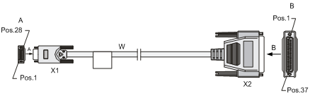
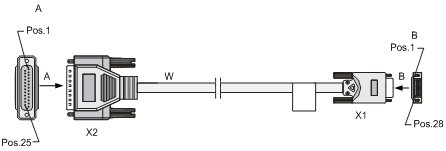
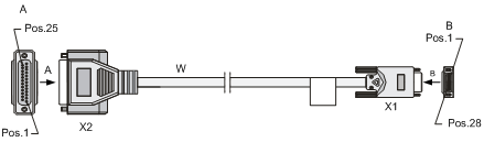
Connecting the cable
|
|
CAUTION: · Never stare into an open fiber Ethernet port, because invisible rays might be emitted from the port. · Cover the dust cover if no optical fiber connector is connected to the fiber Ethernet port. |
To connect the interface cable:
1. Examine port type of the peer device and choose the synchronous serial interface cable of correct type.
2. Plug the DB-28 end of the synchronous serial interface cable into the DB-28 interface of the SAE interface module.
3. If the WAN uses DDN line, connect the cable to the port of CSU/DSU.
4. Examine the LINK LED on the SAE panel.
? If the LED is on, a link is present.
? If the LED is off, a fault has occurred on the link and signal is out of synchronization. In this case, examine the link.
In the compatibility matrixes, "√" means "Supported" and "×" means "Not supported."
Compatibility matrixes on Comware V5
LPU and router compatibility matrix
Table 74 LPU and router compatibility matrix
|
LPU |
SR6602 |
SR6604 |
SR6608 |
SR6616 |
SR6602-X1/X2 |
SR6604-X |
SR6608-X |
SR6616-X |
|
FIP-10 |
× |
√ |
√ |
√ |
√ |
× |
× |
× |
|
FIP-100 |
× |
√ |
√ |
√ |
× |
× |
× |
× |
|
FIP-110 |
× |
√ |
√ |
√ |
× |
√ |
√ |
√ |
|
FIP-20 |
× |
√ |
√ |
√ |
√ |
× |
× |
× |
|
FIP-200 |
× |
√ |
√ |
√ |
× |
× |
× |
× |
|
FIP-210 |
× |
√ |
√ |
√ |
× |
√ |
√ |
√ |
|
FIP-240 |
× |
√ |
√ |
√ |
× |
√ |
√ |
√ |
|
FIP-300 |
× |
× |
× |
× |
× |
√ |
√ |
√ |
|
FIP-310 |
× |
× |
× |
× |
× |
√ |
√ |
√ |
|
FIP-600 |
× |
× |
× |
× |
× |
√ |
√ |
√ |
|
SAP-48GBE |
× |
√ |
√ |
√ |
× |
√ |
√ |
√ |
|
SAP-24GBP |
× |
√ |
√ |
√ |
× |
√ |
√ |
√ |
|
SAP-48GBP |
× |
√ |
√ |
√ |
× |
√ |
√ |
√ |
|
SAP-4EXP |
× |
× |
× |
× |
× |
√ |
√ |
√ |
LPU and MPU compatibility matrix
Table 75 LPU and MPU compatibility matrix
|
LPU |
RPE-X1 |
RSE-X1 |
RSE-X2 |
MCP-X1 |
MCP-X2 |
|
FIP-10 |
× |
× |
× |
√ |
√ |
|
FIP-100 |
√ |
× |
× |
× |
× |
|
FIP-110 |
√ |
√ |
√ |
× |
× |
|
FIP-20 |
× |
× |
× |
√ |
√ |
|
FIP-200 |
√ |
× |
× |
× |
× |
|
FIP-210 |
√ |
√ |
√ |
× |
× |
|
FIP-240 |
√ |
√ |
√ |
× |
× |
|
FIP-300 |
× |
× |
√ |
× |
× |
|
FIP-310 |
× |
× |
√ |
× |
× |
|
FIP-600 |
× |
× |
√ |
× |
× |
|
SAP-48GBE |
′ |
√ |
√ |
′ |
′ |
|
SAP-24GBP |
′ |
√ |
√ |
′ |
′ |
|
SAP-48GBP |
′ |
√ |
√ |
′ |
′ |
|
SAP-4EXP |
′ |
′ |
√ |
′ |
′ |
MPU and router compatibility matrix
Table 76 MPU and router compatibility matrix
|
MPU |
SR6602 |
SR6604 |
SR6608 |
SR6616 |
SR6602-X1/X2 |
SR6604-X |
SR6608-X |
SR6616-X |
|
RPE-X1 |
× |
√ |
√ |
√ |
× |
× |
× |
× |
|
RSE-X1 |
× |
√ |
√ |
√ |
× |
× |
× |
× |
|
RSE-X2 |
× |
× |
× |
× |
× |
√ |
√ |
√ |
|
MCP-X1 |
× |
√ |
√ |
√ |
× |
× |
× |
× |
|
MCP-X2 |
× |
√ |
√ |
√ |
× |
× |
× |
× |
Compatibility matrixes on Comware V7
LPU and router compatibility matrix
Table 77 LPU and router compatibility matrix
|
LPU |
SR6604 |
SR6608 |
SR6616 |
SR6602-X1/X2 |
SR6604-X |
SR6608-X |
SR6616-X |
|
FIP-20 |
× |
× |
× |
√ |
× |
× |
× |
|
FIP-240 |
√ |
√ |
√ |
× |
√ |
√ |
√ |
|
FIP-300 |
√ |
√ |
√ |
× |
√ |
√ |
√ |
|
FIP-310 |
√ |
√ |
√ |
× |
√ |
√ |
√ |
|
FIP-600 |
√ |
√ |
√ |
× |
√ |
√ |
√ |
|
SAP-4EXP |
× |
× |
× |
× |
√ |
√ |
√ |
|
SAP-20GE2XP |
√ |
√ |
√ |
× |
√ |
√ |
√ |
|
SAP-28GE |
√ |
√ |
√ |
× |
√ |
√ |
√ |
LPU and MPU compatibility matrix
Table 78 LPU and MPU compatibility matrix
|
LPU |
RPE-X3 |
RSE-X3 |
|
FIP-20 |
× |
× |
|
FIP-240 |
√ |
√ |
|
FIP-300 |
√ |
√ |
|
FIP-310 |
√ |
√ |
|
FIP-600 |
√ |
√ |
|
SAP-4EXP |
× |
√ |
|
SAP-20GE2XP |
√ |
√ |
|
SAP-28GE |
√ |
√ |
MPU and router compatibility matrix
Table 79 MPU and router compatibility matrix
|
MPU |
SR6604 |
SR6608 |
SR6616 |
SR6602-X1/X2 |
SR6604-X |
SR6608-X |
SR6616-X |
|
RPE-X3 |
√ |
√ |
√ |
× |
× |
× |
× |
|
RSE-X3 |
× |
× |
× |
× |
√ |
√ |
√ |
Interface module and FIP compatibility matrix
Table 80 Interface module and FIP compatibility matrix
|
Module |
FIP-10 |
FIP-100 |
FIP-110 |
FIP-20 |
FIP-200 |
FIP-210 |
FIP-240 |
FIP-300 |
FIP-310 |
FIP-600 |
|
MIMs |
√ |
√ |
√ |
√ |
√ |
√ |
√ |
√ |
√ |
× |
|
HIMs |
× |
× |
× |
√ |
√ |
√ |
√ |
√ |
√ |
√ |
Interface module&SAP and transceiver module compatibility matrix
Table 81 Interface module&SAP and transceiver module compatibility matrix (1)
|
Interface module&SAP |
155 Mbps fiber SFP transceiver module |
622 Mbps fiber SFP transceiver module |
1000 Mbps fiber SFP transceiver module |
100/1000 Mbps fiber SFP transceiver module |
|
|
MIMs |
MIM-2GBE |
× |
× |
× |
× |
|
MIM-1POS |
√ |
× |
× |
× |
|
|
MIM-8E1 |
× |
× |
× |
× |
|
|
MIM-8E1-F |
× |
× |
× |
× |
|
|
MIM-8T1 |
× |
× |
× |
× |
|
|
MIM-8T1-F |
× |
× |
× |
× |
|
|
MIM-1CE3 |
× |
× |
× |
× |
|
|
MIM-1CT3 |
× |
× |
× |
× |
|
|
MIM-1ATM-OC3 |
√ |
× |
× |
× |
|
|
MIM-2SAE |
× |
× |
× |
× |
|
|
MIM-4SAE |
× |
× |
× |
× |
|
|
MIM-8SAE |
× |
× |
× |
× |
|
|
MIM-IMA-4E1 |
× |
× |
× |
× |
|
|
MIM-IMA-8E1 |
× |
× |
× |
× |
|
|
MIM-IMA-4T1 |
× |
× |
× |
× |
|
|
HIMs |
HIM-8FE |
× |
× |
× |
× |
|
HIM-4GBE |
× |
× |
× |
× |
|
|
HIM-8GBE |
× |
× |
× |
× |
|
|
HIM-4GBP |
√ |
× |
√ |
√ |
|
|
HIM-8GBP |
√ |
× |
√ |
√ |
|
|
HIM-1EXP |
× |
× |
× |
× |
|
|
HIM-CL1P |
√ |
× |
× |
× |
|
|
HIM-CL2P |
√ |
× |
× |
× |
|
|
HIM-CLS1P |
√ |
× |
× |
× |
|
|
HIM-CLS2P |
√ |
× |
× |
× |
|
|
HIM-MSP2P |
√ |
√ |
× |
× |
|
|
HIM-MSP4P |
√ |
√ |
× |
× |
|
|
HIM-PS1P |
× |
× |
× |
× |
|
|
HIM-AL1P |
√ |
× |
× |
× |
|
|
HIM-AL2P |
√ |
× |
× |
× |
|
|
HIM-RS2P |
× |
× |
× |
× |
|
|
HIM-4G4P |
√ |
× |
√ |
√ |
|
|
HIM-TS8P |
√ |
√ |
√ |
√ |
|
|
HIM-8GBP-V2 |
√ |
′ |
√ |
√ |
|
|
HIM-16GBP |
√ |
′ |
√ |
√ |
|
|
HIM-2EXP |
′ |
′ |
′ |
′ |
|
|
SAPs |
SAP-48GBE |
× |
× |
× |
× |
|
SAP-24GBP |
√ |
′ |
√ |
√ |
|
|
SAP-48GBP |
√ |
′ |
√ |
√ |
|
|
SAP-4EXP |
× |
× |
× |
× |
|
|
SAP-20GE2XP |
√ |
′ |
√ |
√ |
|
|
SAP-28GE |
√ |
′ |
√ |
√ |
|
Table 82 Interface module and transceiver module compatibility matrix (2)
|
Interface module&SAP |
10/100/1000 Mbps copper SFP transceiver module |
2.5 Gbps fiber SFP transceiver module |
10 Gbps fiber XFP transceiver module |
10 Gbps fiber SFP+ transceiver module |
|
|
MIMs |
MIM-2GBE |
× |
× |
× |
′ |
|
MIM-1POS |
× |
× |
× |
′ |
|
|
MIM-8E1 |
× |
× |
× |
′ |
|
|
MIM-8E1-F |
× |
× |
× |
′ |
|
|
MIM-8T1 |
× |
× |
× |
′ |
|
|
MIM-8T1-F |
× |
× |
× |
′ |
|
|
MIM-1CE3 |
× |
× |
× |
′ |
|
|
MIM-1CT3 |
× |
× |
× |
′ |
|
|
MIM-1ATM-OC3 |
× |
× |
× |
′ |
|
|
MIM-2SAE |
× |
× |
× |
′ |
|
|
MIM-4SAE |
× |
× |
× |
′ |
|
|
MIM-8SAE |
× |
× |
× |
′ |
|
|
MIM-IMA-4E1 |
× |
× |
× |
′ |
|
|
MIM-IMA-8E1 |
× |
× |
× |
′ |
|
|
MIM-IMA-4T1 |
× |
× |
× |
′ |
|
|
HIMs |
HIM-8FE |
× |
× |
× |
′ |
|
HIM-4GBE |
× |
× |
× |
′ |
|
|
HIM-8GBE |
× |
× |
× |
′ |
|
|
HIM-4GBP |
√ |
× |
× |
′ |
|
|
HIM-8GBP |
√ |
× |
× |
′ |
|
|
HIM-1EXP |
× |
× |
√ |
′ |
|
|
HIM-CL1P |
× |
× |
′ |
′ |
|
|
HIM-CL2P |
× |
× |
′ |
′ |
|
|
HIM-CLS1P |
× |
× |
′ |
′ |
|
|
HIM-CLS2P |
× |
× |
′ |
′ |
|
|
HIM-MSP2P |
× |
× |
× |
′ |
|
|
HIM-MSP4P |
× |
× |
× |
′ |
|
|
HIM-PS1P |
× |
√ |
′ |
′ |
|
|
HIM-AL1P |
× |
× |
× |
′ |
|
|
HIM-AL2P |
× |
× |
× |
′ |
|
|
HIM-RS2P |
× |
√ |
× |
′ |
|
|
HIM-4G4P |
√ |
′ |
′ |
′ |
|
|
HIM-TS8P |
√ |
′ |
′ |
′ |
|
|
HIM-8GBP-V2 |
√ |
′ |
′ |
′ |
|
|
HIM-16GBP |
√ |
′ |
′ |
′ |
|
|
HIM-2EXP |
′ |
′ |
′ |
√ |
|
|
SAPs |
SAP-48GBE |
′ |
′ |
′ |
′ |
|
SAP-24GBP |
√ |
′ |
′ |
′ |
|
|
SAP-48GBP |
√ |
′ |
′ |
′ |
|
|
SAP-4EXP |
′ |
′ |
′ |
√ |
|
|
SAP-20GE2XP |
√ |
′ |
′ |
√ |
|
|
SAP-28GE |
√ |
′ |
′ |
′ |
|
Compatibility matrixes on Comware V5,70
Compatibility matrixes on Comware V7,71
Connecting a CE3/CT3 interface cable,66
Connecting a serial interface cable,67
Connecting a T1 interface cable,65
Connecting an E1 interface cable,62
Connecting an Ethernet interface cable,59
Connecting an optical interface cable,60
HIMs,1
Interface module and FIP compatibility matrix,72
Interface module&SAP and transceiver module compatibility matrix,73
MIMs,31
SAPs,42