- Table of Contents
-
- 13-Network Management and Monitoring Configuration Guide
- 00-Preface
- 01-System Maintenance and Debugging Configuration
- 02-NQA Configuration
- 03-NTP Configuration
- 04-Clock Monitoring Configuration
- 05-IPC Configuration
- 06-SNMP Configuration
- 07-RMON Configuration
- 08-CWMP Configuration
- 09-Sampler Configuration
- 10-Mirroring Configuration
- 11-Protocol Packet Statistics Configuration
- 12-sFlow Configuration
- 13-Information Center Configuration
- 14-Packet Capture Configuration
- Related Documents
-
| Title | Size | Download |
|---|---|---|
| 04-Clock Monitoring Configuration | 120.33 KB |
Classification of clock sources
Working mode of the clock monitoring module
Clock monitoring module configuration task list
Configuring working mode of the clock monitoring module
Setting the priority of a reference source
Configuring SSM for reference sources
Setting the way to assign an SSM quality level to a Bits clock source
Setting the SSM bit for a Bits clock source
Configuring an SSM quality level for a reference source
Setting the input port of the line clock (LPU port)
Displaying and maintaining the clock monitoring module
Clock monitoring module configuration example
Overview
Clock monitoring module provides highly precise and reliable SDH line interface clock signals for interface cards. It implements functions including automatic input clock source selection, software phase-lock, and real-time clock status monitoring. The clock monitoring module also supports hardware resetting the clock card.
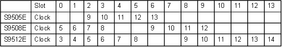
The clock monitoring module supports 14 reference clock sources (also called "reference sources" in this document). The first two reference sources are Bits clock sources, and the others are line clock sources. Each reference source corresponds to a slot, and the reference source and slot mappings vary with devices. Figure 1 shows the reference and slot mappings for the S9500E switch series.
Figure 1 Reference source and slot mappings
Classification of clock sources
Clock sources are classified into the following categories:
· Local clock—38.88 MHz clock signals generated by a crystal oscillator inside the clock monitoring module.
· Bits clock—Clock signals generated by a specific Bits clock device. The signals are sent to the clock monitoring module through a specific interface on the MPU and then sent to all cards by the clock monitoring module.
· Line clock—Provided by the upper level device connected to a WAN interface, a line clock is less precise than a Bits clock source. The clock monitoring module receives line clock signals from the WAN interface and sends them to all cards.
Reference source level
The reference source level is determined by both the priority and the synchronization status marker (SSM) level of the reference source.
A higher priority reference source is more likely to be selected as the clock source.
SSM indicates the synchronization timing signal quality on a synchronization timing transmission link. The following are the SSMs of different clock signals, from high to low:
· PRC—G.811 clock signal.
· TNC—G.812 transit node clock signal.
· LNC—G.812 local node clock signal.
· SETS—SDH device clock source signal.
· Unknown—Unknown synchronization quality.
· DNU—Cannot be used as a clock source.
Working mode of the clock monitoring module
The clock monitoring module can operate in manual mode or auto mode.
Manual mode
In this mode, you manually set the clock source. The clock monitoring module traces the clock source but does not automatically change it. If the primary reference source is lost, the clock monitoring module enters a holdover state.
Auto mode
In auto mode, the system automatically selects the clock source. When the primary clock source is lost or not available, the clock monitoring module selects a new source, as follows:
· If the SSM feature is not activated, selects the reference source with higher priority. If two reference sources have the same priority, selects the one with smaller reference source number (1 to 14). If the reference source with the highest priority is lost, selects the next available reference source with the highest priority. When the former clock source becomes available, uses that clock again.
· If the SSM feature is activated, selects the reference source that has the highest SSM quality level. If two reference sources have the same SSM quality level, uses the reference source priority to make a selection decision. The following clock sources are excluded from clock selection:
¡ Clock sources whose signals are lost.
¡ Clock sources with a priority of 255.
¡ Clock sources with DNU SSM.
Port clock working mode
|
|
IMPORTANT: If connected to a SONET/SDH switch, the switch must be set in slave clock mode, because the SONET/SDH clock is more precise. |
A port clock can operate in one of the following modes:
· Master mode—The port uses the clock signals provided by the clock monitoring module. If you have configured a line clock input port, the clock monitoring module provides the clock signals derived from the line clock input port. If not, the clock monitoring module provides the clock signals generated by the local clock.
· Slave mode—The port uses the line clock signals. The line clock input port must be set in slave mode.
Clock monitoring module configuration task list
|
Task |
Remarks |
|
Optional. |
|
|
Optional. |
|
|
Configuring SSM for reference sources: · Setting the way to assign an SSM quality level to a Bits clock source · Setting the SSM bit for a Bits clock source |
Optional. |
|
Optional. |
Configuring working mode of the clock monitoring module
|
Step |
Command |
Remarks |
|
1. Enter system view. |
system-view |
N/A |
|
2. Set the working mode of the clock monitoring module. |
clock { auto | manual source source-number } |
The default working mode is auto. |
It takes a period of time for the new mode setting to take effect. You can use the display clock device command or logs to verify the configuration.
Setting the priority of a reference source
In auto mode, the clock monitoring module automatically selects a reference source as its clock source based on SSM level and reference source priority.
To set the priority of a reference source:
|
Step |
Command |
Remarks |
|
1. Enter system view. |
system-view |
N/A |
|
2. Assign a priority to the reference source. |
clock priority value source source-number |
The default priority is 255. |
Configuring SSM for reference sources
Setting the way to assign an SSM quality level to a Bits clock source
You can manually assign an SSM quality level to a Bits clock source or configure the system to automatically derive the SSM quality level from the clock signals received from the input line clock.
To set the way to assign an SSM quality level to a Bits clock source:
|
Step |
Command |
Remarks |
|
1. Enter system view. |
system-view |
N/A |
|
2. Set the way to derive the SSM quality level. |
clock forcessm { on | off } source source-number |
By default, you must manually assign an SSM quality level to a Bits clock source. |
Setting the SSM bit for a Bits clock source
As defined in ITU-TG.704 CRC4, the SSM quality level of a Bits clock can be conveyed in the sa4, sa5, sa6, sa7, or sa8 bit in every even frame of multiframes in timeslot 0.
To set the bit for transmitting the SSM quality level of a Bits clock source:
|
Step |
Command |
Remarks |
|
1. Enter system view. |
system-view |
N/A |
|
2. Set the SSM bit for the Bits clock source. |
clock sa-bit { sa4 | sa5 | sa6 | sa7 | sa8 } source source-number |
The default setting is sa4. |
Configuring an SSM quality level for a reference source
The SSM quality level of a reference source is determined as follows:
· Line clock source—User-configured SSM level.
· Bits clock source—If the input signal is 2048 kbit/s (E1) signal and the clock forcessm off source source-number command has been configured, the SSM quality level derived from the input signal takes effect. If the input signal is 2048 kHz or 2048 kbit/s and the clock forcessm on source source-number command has been configured, the user-configured SSM quality level takes effect.
DNU reference sources cannot be used as clock sources. If you assign the DNU level to a reference source, the clock monitoring module in auto mode ignores it when making a clock source selection.
To set an SSM level for a reference source:
|
Step |
Command |
Remarks |
|
1. Enter system view. |
system-view |
N/A |
|
2. Assign an SSM quality level to a reference source. |
clock ssm { dnu | lnc | prc | sets | tnc | unknown } source source-number |
The default setting is unknown. It takes a period of time for the new SSM quality level setting to take effect. You can use the display clock device command or logs to verify the configuration. |
Activating/deactivating SSM
To use the SSM quality level as a criterion for the clock monitoring module to make its clock source selection decision in auto mode, you must activate SSM. If SSM is deactivated, the clock monitoring module bases its clock source selection decision on clock source priority.
To activate or deactivate SSM:
|
Step |
Command |
Remarks |
|
1. Enter system view. |
system-view |
N/A |
|
2. Activate or deactivate SSM. |
clock ssmcontrol { on | off } |
By default, SSM is deactivated. |
Setting the input port of the line clock (LPU port)
For a POS interface card, if you set the port clock to operate in slave mode, you must use the clock lpuport command to set the input port of the card clock source.
To set the input port of the line clock:
|
Step |
Command |
Remarks |
|
1. Enter system view. |
system-view |
N/A |
|
2. Set the input port of the line clock. |
clock lpuport interface-type interface-number |
Optional. By default, the clock input port is the first configurable port by port name in alphabetical order of the interface card. |
|
3. Enter interface view (POS interface). |
interface interface-type interface-number |
N/A |
|
4. Set the input interface to operate in slave mode. |
clock slave |
Optional. By default, the input interface operates in slave mode. |
Displaying and maintaining the clock monitoring module
|
Task |
Command |
Remarks |
|
Display the current configuration of the clock monitoring module. |
display clock config [ | { begin | exclude | include } regular-expression ] |
Available in any view. |
|
Display detailed information about the clock monitoring module. |
display clock device [ | { begin | exclude | include } regular-expression ] |
Available in any view. |
|
Display information about line clock input ports. |
display clock lpuport [ | { begin | exclude | include } regular-expression ] |
Available in any view. |
|
Display the lock state of the clock monitoring module. |
display clock phase-lock-state [ | { begin | exclude | include } regular-expression ] |
Available in any view. |
|
Display the priority of all reference sources. |
display clock priority [ | { begin | exclude | include } regular-expression ] |
Available in any view. |
|
Display the self-test result of the clock monitoring module. |
display clock self-test-result [ | { begin | exclude | include } regular-expression ] |
Available in any view. |
|
Display the state of all reference sources. |
display clock source [ | { begin | exclude | include } regular-expression ] |
Available in any view. |
|
Display the SSM quality level of reference sources. |
display clock ssm-level [ | { begin | exclude | include } regular-expression ] |
Available in any view. |
|
Display the SSM quality level of output clock signals. |
display clock ssm-output [ | { begin | exclude | include } regular-expression ] |
Available in any view. |
|
Display the clock monitoring module version. |
display clock version [ | { begin | exclude | include } regular-expression ] |
Available in any view. |
|
Display the working mode of the clock monitoring module. |
display clock work-mode [ | { begin | exclude | include } regular-expression ] |
Available in any view. |
Clock monitoring module configuration example
By default, Ethernet, VLAN, and aggregate interfaces are in DOWN state. To configure these interfaces, use the undo shutdown command to bring up these interfaces first.
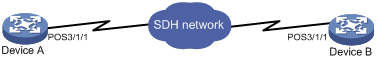
Network requirements
In Figure 2, Device A has a clock monitoring module for clock synchronization, and Device B uses the line clock from Device A for time synchronization on the SDH line.
Configuration procedure
1. Configure Device A (master clock):
# Set POS 3/1/1 to operate in master clock mode.
<DeviceA> system-view
[DeviceA] interface pos 3/1/1
[DeviceA-Pos3/1/1] clock master
2. Configure Device B (slave clock):
# Set the line clock source input interface to POS 3/1/1.
<DeviceB> system-view
[DeviceB] clock lpuport pos 3/1/1
# Set POS 3/1/1 to operate in slave clock mode.
[DeviceB] interface pos 3/1/1
[DeviceB-Pos3/1/1] clock slave
[DeviceB-Pos3/1/1] quit
# Use the line clock source from POS 3/1/1 (clock source 8 in this example) as the primary clock source. (For clock source and slot mappings, see Figure 1.)
[DeviceB] clock manual source 8
The settings make sure all WAN interface cards on Device B to be synchronized to the highly precise and reliable line clock from POS 3/1/1.