- Table of Contents
- Related Documents
-
| Title | Size | Download |
|---|---|---|
| 01-MCE Configuration | 436.1 KB |
Table of Contents
Routing Information Exchange for MCE
Route Exchange between an MCE and the Private Network
Route Exchange between MCE and PE
VPN Instance Configuration Task List
Associating an VPN Instance with an Interface
Configuring the Route-related Attributes for a VPN Instance
Configuring Route Exchange between a MCE and a Site
Configuring Route Exchange between a MCE and a Site
Configuring to Use Static Routes between a MCE and a Site
Configuring to Use RIP between a MCE and a Site
Configuring to Use OSPF between a MCE and a Site
Configuring to Use IS-IS between a MCE and a Site
Configuring to Use EBGP between a MCE and a Site
Configuring Route Exchange between a MCE and a PE
Configuring Route Exchange between a MCE and a PE
Configuring to Use Static Routes between a MCE and a PE
Configuring to Use RIP between a MCE and a PE
Configuring to Use OSPF between a MCE and a PE
Configure to Use IS-IS between a MCE and a PE
Configure to Use EBGP between a MCE and a PE
Displaying and Maintaining MCE
![]()
The term “router” in this document refers to a router in a generic sense or a Layer 3 switch running routing protocols.
MCE Overview
Multi-CE (MCE) enables a switch to function as the CEs of multiple VPN instances in a BGP/MPLS VPN network, thus reducing the investment on network equipment.
Introduction to BGP/MPLS VPN
BGP/MPLS VPN is a kind of PE-based L3VPN technology for service provider VPN solutions. It uses BGP to advertise VPN routes and uses MPLS to forward VPN packets on the service provider backbone.
BGP/MPLS VPN provides flexible networking modes, excellent scalability, and convenient support for MPLS QoS and MPLS TE. Hence, it is widely used.
The BGP/MPLS VPN model consists of three kinds of devices:
l Customer edge device (CE): A CE resides on a customer network and has one or more interfaces directly connected with service provider networks. It can be a router, a switch, or a host. It neither can "sense" the existence of any VPN nor needs to support MPLS.
l Provider edge router (PE): A PE resides on a service provider network and connects one or more CEs to the network. On an MPLS network, all VPN processing occurs on the PEs.
l Provider (P) router: A P router is a backbone router on a service provider network. It is not directly connected with any CE. It only needs to be equipped with basic MPLS forwarding capability.
Figure 1-1 illustrates a BGP/MPLS VPN implementation.
Figure 1-1 A BGP/MPLS VPN implementation
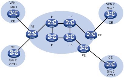
CEs and PEs mark the boundary between the service providers and the customers.
A CE is usually a router. After a CE establishes adjacency with a directly connected PE, it redistributes its VPN routes to the PE and learns remote VPN routes from the PE. A CE and a PE use BGP/IGP to exchange routing information. You can also configure static routes between them.
After a PE learns the VPN routing information of a CE, it uses BGP to exchange VPN routing information with other PEs. A PE maintains routing information about only VPNs that are directly connected, rather than all VPN routing information on the provider network.
A P router maintains only routes to PEs. It does not need to know anything about VPN routing information.
When VPN traffic travels over the MPLS backbone, the ingress PE functions as the ingress LSR, the egress PE functions as the egress LSR, while P routers function as the transit LSRs.
You can use H3C S7500E series switches as the CEs in a BGP/MPLS VPN implementation.
BGP/MPLS VPN Concepts
Site
Site is often mentioned in the VPN, whose meanings are described as follows:
l A site is a group of IP systems with IP connectivity that does not rely on any service provider network to implement.
l The classification of a site depends on the topology relationship of the devices, rather than the geographical positions, though the devices at a site are adjacent to each other geographically in most cases.
l The devices at a site can belong to multiple VPNs, namely, a site can belong to multiple VPNs.
l A site is connected to a provider network through one or more CEs. A site can contain many CEs, but a CE can belong to only one site.
Sites connected to the same provider network can be classified into different sets by policies. Only the sites in the same set can access each other through the provider network. Such a set is called a VPN.
Address space overlapping
Each VPN independently manages the addresses that it uses. The assembly of such addresses for a VPN is called an address space.
The address spaces of VPNs may overlap. For example, if both VPN 1 and VPN 2 use the addresses in network segment 10.110.10.0/24, address space overlapping occurs.
VPN instance
In MPLS VPN, route separation between VPNs is implemented by VPN instance.
A PE creates and maintains a separate VPN instance for each directly connected site. Each VPN instance contains the VPN membership and routing rules of the corresponding site. If a user at a site belongs to multiple VPNs at the same time, the VPN instance of the site contains information about all the VPNs.
For independency and security of VPN data, each VPN instance on a PE maintains a relatively independent routing table and a separate label forwarding information base (LFIB). VPN instance information contains these items: the LFIB, IP routing table, interfaces bound to the VPN instance, and administration information of the VPN instance. The administration information of the VPN instance includes the route distinguisher (RD), route filtering policy, and member interface list.
![]()
LFIBs of VPN instances exist on only PEs supporting MPLS. No LFIBs of VPN instances exist on MCE-capable devices.
VPN-IPv4 address
Traditional BGP cannot process VPN routes which have overlapping address spaces. If, for example, both VPN 1 and VPN 2 use addresses in the segment 10.110.10.0/24 and advertise a route to the segment, BGP selects only one of them, which results in loss of the other route.
PEs use MP-BGP to advertise VPN routes, and use VPN-IPv4 address family to solve the problem with traditional BGP.
A VPN-IPv4 address consists of 12 bytes. The first eight bytes represent the RD, followed by a 4-byte IPv4 address prefix, as shown in.
Figure 1-2 Structure of a VPN-IPv4 address

When a PE receives an ordinary IPv4 route from a CE, it must redistribute the VPN route to the peer PE. The uniqueness of a VPN route is implemented by adding an RD to the route.
A service provider can independently assign RDs provided the assigned RDs are unique. In this way, a PE can advertise different routes to VPNs even if the VPNs are from different service providers and are using the same IPv4 address space.
You are recommended to configure a distinct RD for each VPN instance on a PE, guaranteeing that routes to the same CE use the same RD. The VPN-IPv4 address with an RD of 0 is in fact a globally unique IPv4 address.
By prefixing a distinct RD to a specific IPv4 address prefix, you make it a globally unique VPN IPv4 address prefix.
An RD can be related to an autonomous system (AS) number, in which case it is the combination of an AS number and a discretionary number; or be related to an IP address, in which case it is the combination of an IP address and a discretionary number.
An RD can be in either of the following two formats distinguished by the Type field:
l When the value of the Type field is 0, the Administrator subfield occupies two bytes, the Assigned number subfield occupies four bytes, and the RD format is: 16-bit AS number:32-bit user-defined number. For example, 100:1.
l When the value of the Type field is 1, the Administrator subfield occupies four bytes, the Assigned number subfield occupies two bytes, and the RD format is: 32-bit IPv4 address:16-bit user-defined number. For example, 172.1.1.1:1.
For the global uniqueness of an RD, you are not recommended to set the Administrator subfield to any private AS number or private IP address.
VPN target attributes
BGP/MPLS VPN uses the BGP extended community attributes called VPN target attributes, or route target attributes, to control the advertisement of VPN routing information.
A VPN instance on a PE supports two types of VPN target attributes:
l Export target attribute: A local PE sets this type of VPN target attribute for VPN-IPv4 routes learnt from directly connected sites before advertising them to other PEs.
l Import target attribute: A PE checks the export target attribute of VPN-IPv4 routes advertised by other PEs. If the export target attribute matches the import target attribute of the VPN instance, the PE adds the routes to the VPN routing table.
In other words, VPN target attributes define which sites can receive a VPN-IPv4 route, and from which sites a PE can receive routes.
Like RDs, VPN target attributes can be of two types of formats:
l 16-bit AS number:32-bit user-defined number. For example, 100:1.
l 32-bit IPv4 address:16-bit user-defined number. For example, 172.1.1.1:1.
Introduction to MCE
With BGP/MPLS VPN, data of private networks can be transmitted in the public network securely through tunnels. However, in a typical BGP/MPLS VPN network, each VPN is connected to the PE through a CE, as shown in Figure 1-1.
With the users’ increasing demand for service segmentation and security, a private network may be divided into multiple VPNs, and the users of different VPN are usually isolated from each other. In a private network containing multiple VPNs, users may be in such a dilemma: equipment investment and the maintenance cost increment caused by assigning a CE for each of the VPNs; and potential data security risks introduced by sharing one CE among multiple VPNs (because the same routing entry may be used in multiple VPNs in this case).
An S7500E switch with MCE enabled can solve this problem. By binding the VLAN interfaces to the VPNs in a network on an S7500E switch of this kind, you can create and maintain a routing table for each of the VPNs. In this way, packets of different VPNs in the private network can be isolated. Moreover, with the cooperation of the PE, the routes of each VPN can be advertised to the corresponding remote PE properly, so that packets of each VPN in the private network can be transmitted securely through the public network.
How MCE Works
Figure 1-3 illustrates how MCE creates and maintains routing entries of multiple VPNs and how the MCE exchanges VPN routes with PEs.

In Figure 1-3, the two VPN sites on the left side (Site 1 and Site 2) are connected to the backbone network through an MCE device. Two VPN tunnels are expected between them and the remote VPNs at Site 2 and Site 1.
With MCE enabled, routing tables can be created for VPN 1 and VPN 2 individually, VLAN-interface 2 can be bound to VPN 1, and VLAN-interface 3 can be bound to VPN 2. When receiving a piece of routing information, MCE determines the source of the routing information according to the number of the interface receiving the information and then maintains the corresponding routing table accordingly.
You need to also to bind the interfaces to the VPNs on PE 1 in the same way as those on the MCE device. The MCE device is connected to PE 1 through a trunk, which permits packets of VLAN 2 and VLAN 3 with VLAN tags carried. In this way, PE 1 can determine the VPN a received packet belongs to according to the VLAN tag of the packet and passes the packet to the corresponding tunnel.
Routing Information Exchange for MCE
Interface-to-VPN-instance binding enables CEs and PEs to determine the sources of received packets and then forward the packets according to the routing information concerning the corresponding VPNs. The following sections describe the way how MCE transmits the private routing information of multiple VPNs to PEs properly.
Route Exchange between an MCE and the Private Network
An MCE can adopt the following routing protocols to exchange VPN routes with a site:
l Static route
l RIP
l OSPF
l IS-IS
l EBGP
![]()
This introduces the cooperation of routing protocols and MCE in brief. For details on routing protocols, see the IP Routing Volume module of this manual.
Static routes
An MCE can communicate with a site through static routes. As static routes configure for traditional CEs take effect globally, address overlapping between multiple VPNs remains a problem till the emergence of MCE. MCE allows static-route-to-VPN-instance binding, which isolates the static routes of different VPNs.
RIP
An S7500E switch can bind RIP processes to VPN instances. With the same binding configured on MCE and site, private network routes of different VPNs can be exchanged between MCEs and sites through different RIP processes, thus isolating and securing VPN routes.
OSPF
An S7500E switch can bind OSPF processes to VPN instances and isolate the routes of different VPNs.
Note that:
For an OSPF process bound to a VPN instance, the router ID of the public network configured in system view is invalid. So you need to specify the router ID when creating an OSPF process.
An OSPF process can be bound to only one VPN instance, however, a VPN instance can use multiple OSPF processes for private network route transmission. To make sure routes can be advertised properly, you need to configure the same domain ID for all the OSPF processes bound to a VPN instance.
![]()
Normally, when an OSPF route is imported to the BGP routing table as a BGP route on a PE, some attributes of the OSPF route get lost. When the BGP route is imported to the OSPF routing table on the remote CE, not all the attributes of the original OSPF routes can be restored. As a result, the route cannot be distinguished from the routes imported from other domains. In order to distinguish OSPF routes imported from different OSPF domains, the OSPF routes to be imported to the BGP routing tables on PEs must carry an attribute (the OSPF domain ID) used to identify the OSPF domains. The domain ID of an OSPF process is contained in the routes generated by the process. When an OSPF route is imported to BGP, the domain ID is added to BGP VPN routes as the extended BGP community.
In cases where a VPN have multiple MCE devices attached to it, when a MCE device advertises the routes learned from BGP within the VPN, the routes may be learned by other MCE devices, thus generating route loops. To prevent route loops, you can configure route tags for different VPN instances on each MCE. It is recommended that a VPN be assigned the same route tag on multiple MCEs.
IS-IS
Similar to those in OSPF, IS-IS processes can be bound to VPN instances for private network routes to be exchanged between MCEs and sites. An IS-IS process can be bound to only one VPN instance.
EBGP
To use EBGP to exchange private routes between an MCE and a site, you need to configure BGP peers for VPN instances on MCEs and import IGP routing information from corresponding VPNs. Normally, sites reside in different ASs, so EBGP is used for route exchange. In this case, the following configurations are needed.
1) Configuring to use EBGP to import IGP routes from each site
To advertise private network routes to PEs properly, IGP routes in the sites directly connected to an MCE device need to be first imported to the BGP routing table of the MCE device.
2) Configuring a peer group for each VPN instance
For proper route exchange between a CE and a site, you need to configure a peer group for each VPN instance and assign AS numbers for these peer groups in BGP IPv4 address family view.
3) Applying filtering policies for route filtering
To make sure that routing information is exchanged between sites and PE devices properly, filtering policies are applied to filter routes received or to be advertised.
Route Exchange between MCE and PE
Routing information entries are bound to specific VPN instances on an MCE device, and packets of each VPN instance are forwarded between MCE and PE according to interface. As a result, VPN routing information can be transmitted by performing relatively simple configurations between MCE and PE, such as importing the VPN routing entries on MCE devices to the routing table of the routing protocol running between MCEs and PEs.
The following routing protocols can be used between MCE and PE for routing formation exchange:
l Static route
l RIP
l OSPF
l IS-IS
l EBGP
For information on how to configure the routing protocols and how to import routes, refer to the IP Routing Volume of this manual.
![]()
For detailed information on the routing protocol configuration mentioned in this chapter, see the IP Routing Volume of this manual.
Configuring a VPN Instance
VPN Instance Configuration Task List
Complete the following tasks to configure a VPN instance:
|
Task |
Remarks |
|
Required |
|
|
Required |
|
|
Required |
Creating a VPN Instance
A VPN instance needs to be associated with a site. A VPN instance does not correspond to a VPN directly. Instead, a VPN instance is an integration of the VPN membership and routing rules of its corresponding site.
A VPN instance takes effect only after a route distinguisher (RD) is configured for it. For a VPN instance with the RD not configured, all the other settings (except the description information) are inaccessible.
Follow these steps to create a VPN instance:
|
To do… |
Use the command… |
Remarks |
|
Enter system view |
system-view |
— |
|
Create a VPN instance and enter VPN instance view |
ip vpn-instance vpn-instance-name |
Required By default, no VPN instance is present. |
|
Configure an RD for the VPN instance |
route-distinguisher route-distinguisher |
Required By default, a VPN instance has no RD configured. |
|
Set the description information for the VPN instance |
description text |
Optional By default, a VPN instance has no description configured. |
![]()
For easy management, you are recommended to set the same RD for the same VPN instance on the MCE and PE.
Associating an VPN Instance with an Interface
Follow these steps to associate an VPN instance with an interface:
|
To do… |
Use the command… |
Remarks |
|
Enter system view |
system-view |
— |
|
Enter interface view of the interface to be associated |
interface interface-type interface-number |
— |
|
Associate the current interface with the VPN instance |
ip binding vpn-instance vpn-instance-name |
Required By default, no interface is associated with a VPN instance. |
![]()
Executing the ip binding vpn-instance command invalidates the IP address configured for the current interface, so you need to configure an IP address for an interface again after associating the interface with a VPN instance.
Configuring the Route-related Attributes for a VPN Instance
The process of advertising VPN routes is as follows:
l When the switch learns a VPN route from a site and injects it into BGP, BGP associates the route with a VPN target extended community attribute list, which is normally the export route attribute list of the VPN instance.
l A VPN instance determines whether to accept a received route according to the VPN target import extended community attribute list associated with the route and the setting specified by the vpn-target command.
Follow these steps to configure the route-related attributes for a VPN instance:
|
To do… |
Use the command… |
Remarks |
|
Enter system view |
system-view |
— |
|
Enter VPN instance view |
ip vpn-instance vpn-instance-name |
— |
|
Associate the current VPN instance with one or multiple VPN targets |
vpn-target vpn-target&<1-8> [ both | export-extcommunity | import-extcommunity ] |
Required By default, a VPN instance has no VPN target associated with it. |
|
Configure the maximum number of routes a VPN instance can accommodate |
routing-table limit number { warn-threshold | simply-alert } |
Optional Not configured by default |
|
Apply a route policy for the routes received |
import route-policy route-policy |
Optional By default, all routes matching the VPN target attribute are permitted. |
|
Apply a route policy for the routes to be advertised |
export route-policy route-policy |
Optional By default, all routes matching the VPN target attribute are permitted. |
![]()
l This attribute can be advertised with a route only when BGP runs between the MCE and the PE. Otherwise, this attribute is of no sense.
l The VPN target specified for a VPN instance on the MCE device must be same as that specified for the VPN instance on the PE device.
l You can define the maximum number of routes for a VPN instance to support, preventing too many routes from being redistributed into the PE.
l Before associating a routing policy with a VPN instance, you must create the routing policy at first. Otherwise, the default routing policy is used.
Configuring Route Exchange between a MCE and a Site
Configuring Route Exchange between a MCE and a Site
Complete the following tasks to configure route exchange between a MCE and a site:
|
Task |
Remarks |
|
You can choose one or multiple configurations as required. |
|
Configuring to Use Static Routes between a MCE and a Site
Follow these steps to configure static routes between a MCE and a site:
|
To do… |
Use the command… |
Remarks |
|
Enter system view |
system-view |
— |
|
Define a static route for a VPN instance |
ip route-static vpn-instance s-vpn-instance-name&<1-5> dest-address { mask | mask-length } { gateway-address [ public ] | interface-type interface-number [ gateway-address ] | vpn-instance d-vpn-instance-name gateway-address } [ preference preference-value ] [ tag tag-value ] [ description description-text ] |
Required This operation is performed on the MCE device. The corresponding configuration on the site is the same as configuring a normal static route. |
|
Configure the default precedence for static routes |
ip route-static default-preference default-preference-value |
Optional 60 by default |
Configuring to Use RIP between a MCE and a Site
Follow these steps to configure RIP between a MCE and a site:
|
To do… |
Use the command… |
Remarks |
|
Enter system view |
system-view |
— |
|
Enable RIP for a VPN instance (This operation also leads you to RIP view) |
rip [ process-id ] vpn-instance vpn-instance-name |
Required This operation is performed on the MCE device. As for the corresponding configuration on the site, you can just enable RIP as usual. |
|
Redistribute routes from the remote site advertised by the PE |
import-route protocol [ process-id ] [ allow-ibgp ] [ cost cost | route-policy route-policy-name | tag tag ] * |
Required By default, RIP does not redistribute routes from other protocols. |
![]()
After enabling RIP for a VPN instance, you need also to configure to use RIP for routing information exchange. For RIP configuration, refer to RIP Configuration in the IP Routing Volume.
Configuring to Use OSPF between a MCE and a Site
Follow these steps to configure OSPF between a MCE and a site:
|
To do… |
Use the command… |
Remarks |
|
Enter system view |
system-view |
— |
|
Enable OSPF for a VPN instance (this operation also leads you to OSPF view) |
ospf [ process-id | router-id router-id | vpn-instance vpn-instance-name ] * |
Required This operation is performed on the MCE device. As for the corresponding configuration on the site, you can just enable OSPF as usual. |
|
Enable multi-VPN-instance CE for the OSPF process |
vpn-instance-capability simple |
Required Disabled by default |
|
Redistribute routes from the remote site advertised by the PE |
import-route protocol [ process-id | allow-ibgp ] [ cost cost | type type | tag tag | route-policy route-policy-name ] * |
Required Not redistributed by default |
|
Configure the OSPF domain ID |
domain-id domain-id [ secondary ] |
Optional By default, the OSPF domain ID is 0. This operation is performed on the MCE device. As for the corresponding configuration on the site, you can just enable OSPF as usual. |
|
Configure the type codes of OSPF extended community attributes |
ext-community-type { domain-id type-code1 | router-id type-code2 | route-type type-code3 } |
Optional The defaults are as follows: 0x0005 for Domain ID, 0x0107 for Router ID, and 0x0306 for Route Type. |
![]()
l Router IDs of the public network configured in system view do not applies to OSPF processes bound to VPN instances. So you need to configure the Router ID after enabling OSPF for a VPN instance.
l An OSPF process can belong to only one VPN instance, but one VPN instance can use multiple OSPF processes to advertise the VPN routes. To make sure routes can be advertised properly, you need to configure the same domain ID for all the OSPF processes bound to a VPN.
l After you configure an OSPF instance, you need to enable OSPF. The configuration procedure is the same as the common OSPF configuration. For OSPF configuration details, refer to OSPF Configuration in the IP Routing Volume.
Configuring to Use IS-IS between a MCE and a Site
Follow these steps to configure IS-IS between a MCE and a site:
|
To do… |
Use the command… |
Remarks |
|
Enter system view |
system-view |
— |
|
Enable IS-IS for a VPN instance and enter IS-IS view |
isis [ process-id ] vpn-instance vpn-instance-name |
Required This operation is performed on the MCE device. As for the corresponding configuration on the site, you can just enable IS-IS as usual. |
|
Redistribute routes from the remote site advertised by the PE |
import-route { isis [ process-id ] | ospf [ process-id ] | rip [ process-id ] | bgp [ allow-ibgp ] | direct | static } [ cost cost | cost-type { external | internal } | [ level-1 | level-1-2 | level-2 ] | route-policy route-policy-name | tag tag ] * |
Required By default, IS-IS does not redistribute routes from other protocols. Without the level specified, the command redistributes routes to the Level-2 routing table by default. |
![]()
After enabling IS-IS for a VPN instance, you need also to configure to use IS-IS for routing information exchange.
Configuring to Use EBGP between a MCE and a Site
1) Configuration on the MCE device
Follow these steps to configure an MCE device:
|
To do… |
Use the command… |
Remarks |
|
Enter system view |
system-view |
— |
|
Enter BGP view |
bgp as-number |
— |
|
Enter BGP-VPN instance view |
ipv4-family vpn-instance vpn-instance-name |
Required |
|
Configure a CE as a VPN peer |
peer { group-name | ip-address } [ as-number as-number ] |
Required |
|
Redistribute routes from the remote site advertised by the PE |
import-route protocol [ process-id ] [ med med-value | route-policy route-policy-name ] * |
Required By default, EBGP does not redistribute routes from other protocols. |
|
Apply a filter policy to the routes to be advertised |
filter-policy { acl-number | ip-prefix ip-prefix-name } export [ direct | isis process-id | ospf process-id | rip process-id | static ] |
Optional By default, routes to be advertised are not filtered. |
|
Apply a filter policy to routes received |
filter-policy { acl-number | ip-prefix ip-prefix-name } import |
Optional By default, received routes are not filtered. |
|
Configure to permit the routes with their AS numbers contained in their AS_PATH attributes being the local AS number (this operation can also specify the number of the AS number occurrences allowed) |
peer { group-name | ip-address } allow-as-loop [ number ] |
Optional By default, routes with their AS numbers contained in their AS_PATH attributes being the local AS number are denied. |
![]()
l AS number contained in the AS_PATH attribute can be used for route loop detect. With EBGP running between a MCE and a site, the routes advertised by an MCE device to the site carry the local AS number. So do the routes advertised by the site. In this case, you need to configure to permit the routes with their AS numbers contained in their AS_PATH attributes being the local AS number on MCE devices for the routes advertised by the site to be received and processed by the MCE device.
l After you configure a BGP VPN instance, the BGP route exchange in the VPN instance is the same as the common BGP’s. For BGP configuration details, refer to BGP Configuration in the IP Routing Volume.
2) Configuration on the site
![]()
The site configuration procedures vary with device model. The following takes an S7500E Ethernet switch as an example. As for switches from other vendors, refer to the corresponding user manuals.
Follow these steps to configure the site:
|
To do… |
Use the command… |
Remarks |
|
Enter system view |
system-view |
— |
|
Enter BGP view |
bgp as-number |
— |
|
Configure the PE as a peer |
peer { group-name | ip-address } as-number as-number |
Required |
|
Configure to import routes |
import-route protocol [ process-id ] [ med med-value | route-policy route-policy-name ] * |
Optional The site must advertise the addresses of the reachable VPN segments to the MCE connected to the site. |
![]()
In a VPN instance with BGP enabled, the BGP route exchange is processed in the same way as those in a normal BGP-enabled network.
Configuring Route Exchange between a MCE and a PE
Configuring Route Exchange between a MCE and a PE
Complete the following tasks to configure route exchange between a MCE and a PE:
|
Task |
Remarks |
|
You can choose one or multiple configurations as required. |
|
Configuring to Use Static Routes between a MCE and a PE
Follow these steps to define a static route for a VPN instance:
|
To do… |
Use the command… |
Remarks |
|
Enter system view |
system-view |
— |
|
Define a static route for a VPN instance |
ip route-static dest-address { mask | mask-length } { gateway-address | interface-type interface-number [ gateway-address ] | vpn-instance d-vpn-instance-name gateway-address } [ preference preference-value ] [ tag tag-value ] [ description description-text ] |
Required By default, for a static route, the preference value is 60, the tag value is 0, and no description information is configured. |
|
ip route-static vpn-instance s-vpn-instance-name&<1-6> dest-address { mask | mask-length } { gateway-address [ public ] | interface-type interface-number [ gateway-address ] | vpn-instance d-vpn-instance-name gateway-address } [ preference preference-value ] [ tag tag-value ] [ description description-text ] |
||
|
Set the default preference value of static routes |
ip route-static default-preference default-preference-value |
Optional By default, the preference value of a static route is 60. |
![]()
l A static route configured for a VPN instance does not take effect if you configure the next hop address of the route as the IP address of a local interface (such as Ethernet interface, VLAN interface).
l If the default static route preference is not configured, the preference of a newly defined static route adopts the system default preference value, which is 60. A customized default static route preference has no effect on existing static routes.
l Static routes can be controlled selectively by using routing policies according to the tag values set for static routes.
l The ip route-static command defines a default route if both the destination address and the mask are set to 0.0.0.0.
Configuring to Use RIP between a MCE and a PE
When configuring to use RIP between a MCE and a PE, you need to configure the RIP processes to be bound to the VPN instances and manually import the VPN routes in the site maintained by the MCE device to the routing table of the PE.
Follow these steps to enable RIP for a VPN instance:
|
To do… |
Use the command… |
Remarks |
|
Enter system view |
system-view |
— |
|
Enable RIP for a VPN instance and enter RIP view |
rip [ process-id ] [ vpn-instance vpn-instance-name ] |
Required |
|
Set the default cost for imported routes |
default cost value |
Optional By default, the cost for an imported route is 0. |
|
Import the VPN routes of the site |
import-route protocol [ process-id ] [ allow-ibgp ] [ cost cost | route-policy route-policy-name | tag tag ] * |
Required By default, RIP does not import routes from other protocols. |
Configuring to Use OSPF between a MCE and a PE
When configuring to use OSPF between a MCE and a PE, you need to configure the OSPF processes to be bound to VPN instances and router IDs; you also need to manually import the VPN routes in the site maintained by the MCE device to the routing table of the PE.
Follow these steps to configure OSPF between a MCE and a PE:
|
To do… |
Use the command… |
Remarks |
|
Enter system view |
system-view |
— |
|
Enable OSPF for a VPN instance and enter OSPF view |
ospf [ process-id | router-id router-id | vpn-instance instance-name ] * |
Required |
|
Enable OSPF to import routes of other protocols |
import-route protocol [ process-id | allow-ibgp ] [ cost cost | type type | tag tag | route-policy route-policy-name ] * |
Required By default, OSPF does not import the routes of other protocols. |
|
Apply a filter policy for imported routes |
filter-policy { acl-number | ip-prefix ip-prefix-name } export [ protocol [ process-id ] ] |
Optional By default, no filter policy is applied. |
|
Configure the default values of the route attributes (including cost, limit, tag, and type) for the routes imported |
default { cost cost | limit limit | tag tag | type type } * |
Optional The default route attributes are as follows: the cost value is 1, the upper limit on the maximum number of imported external routes is 1,000, the tag value is 1, and the type is type2. |
Configure to Use IS-IS between a MCE and a PE
When configuring to use IS-IS between a MCE and a PE, you need to configure the IS-IS processes to be bound to VPN instances and manually import the VPN routes in the site maintained by the MCE device to the routing table of the PE.
In IS-IS, routes discovered by other routing protocols are external routes. While importing routes of other protocols, you can specify the default cost value for the imported routes as well. You can also apply filter policies for imported routes.
Follow these steps to configure IS-IS to import external routes:
|
To do… |
Use the command… |
Remarks |
|
Enter system view |
system-view |
— |
|
Enable IS-IS for a VPN instance and enter IS-IS view |
isis [ process-id ] [ vpn-instance vpn-instance-name ] |
— |
|
Import routes of other protocols |
import-route { isis [ process-id ] | ospf [ process-id ] | rip [ process-id ] | bgp [ allow-ibgp ] | direct | static } [ cost cost | cost-type { external | internal } | [ level-1 | level-1-2 | level-2 ] | route-policy route-policy-name | tag tag ] * |
Required By default, IS-IS does not import routes of other protocols. If none of the level-1, level-2, and level-3 keywords is specified, the external routes are imported to level-2 routing table. |
|
Apply a filter policy for imported routes |
filter-policy { acl-number | ip-prefix ip-prefix-name | route-policy route-policy-name } export [ isis process-id | ospf process-id | rip process-id | bgp | direct | static ] |
Optional By default, no filter policy is applied. |
Configure to Use EBGP between a MCE and a PE
To use EBGP to exchange routing information between a MCE and a PE, you need to configure the peer end as a peer in the BGP-VPNs on both ends, import VPN routes in the site to the MCE, and then advertise these routes to the PE.
Follow these steps to configure EBGP between a MCE and a PE:
|
To do… |
Use the command… |
Remarks |
|
Enter system view |
system-view |
— |
|
Enter BGP view |
bgp as-number |
— |
|
Enter BGP-VPN instance view |
ipv4-family vpn-instance vpn-instance-name |
Required |
|
Configure the PE as a VPN peer |
peer { group-name | ip-address } as-number as-number |
Required |
|
Import routes of the local site |
import-route protocol [ process-id ] [ med med-value | route-policy route-policy-name ] * |
Required The MCE device must import routes of the local site to the VPN routing table in order to advertise these routes to the PE device. |
|
Apply a filter policy for routes to be advertised |
filter-policy { acl-number | ip-prefix ip-prefix-name } export [ direct | isis process-id | ospf process-id | rip process-id | static ] |
Optional By default, no filter policy is applied. |
|
Apply a filter policy for received routes |
filter-policy { acl-number | ip-prefix ip-prefix-name } import |
Optional By default, no filter policy is applied. |
Displaying and Maintaining MCE
|
To do… |
Use the command… |
Remarks |
|
Display the IP routing tables associated with a VPN instance |
display ip routing-table vpn-instance vpn-instance-name [ verbose ] |
Available in any view |
|
Display the information about a VPN instance |
display ip vpn-instance [ instance-name vpn-instance-name ] |
Available in any view |
|
Display information about the FIB of a VPN instance |
display fib vpn-instance vpn-instance-name [ include string ] |
Available in any view |
|
Display information about a specified BGP VPNv4 peer group |
display bgp vpnv4 vpn-instance vpn-instance-name group [ group-name ] |
Available in any view |
|
Display information about BGP VPNv4 routes injected into a specified VPN instance |
display bgp vpnv4 vpn-instance vpn-instance-name network |
Available in any view |
|
Display BGP VPNv4 AS path information |
display bgp vpnv4 vpn-instance vpn-instance-name paths [as-regular-expression ] |
Available in any view |
|
Display information about BGP VPNv4 peers |
display bgp vpnv4 vpn-instance vpn-instance-name peer [ group-name log-info | ip-address { log-info | verbose } | verbose ] |
Available in any view |
|
Display the BGP VPNv4 routing information of a specified VPN instance |
display bgp vpnv4 vpn-instance vpn-instance-name routing-table [ network-address [ { mask | mask-length } [ longer-prefixes ] ] | as-path-acl as-path-acl-number | cidr | community [ aa:nn ]&<1-13>[ no-export-subconfed | no-advertise | no-export ]* [ whole-match ] | community-list { basic-community-list-number [ whole-match ] | adv-community-list-number }&<1-16> | dampened | dampening parameter | different-origin-as | flap-info [ as-path-acl as-path-acl-number | network-address [ mask [ longer-match ] | mask-length [ longer-match ] ] | regular-expression as-regular-expression ] | peer ip-address { advertised-routes | received-routes } | regular-expression as-regular-expression | statistic ] |
Available in any view |
|
Perform a soft reset of the BGP connections in a specified VPN instance |
refresh bgp vpn-instance vpn-instance-name { ip-address | all | external | group group-name } { export | import } |
Available in user view |
|
Reset the BGP connections of a VPN instance |
reset bgp vpn-instance vpn-instance-name { as-number | ip-address | all | external | group group-name } |
Available in user view |
|
Clear the route flap dampening information of a VPN instance |
reset bgp vpn-instance vpn-instance-name dampening [ network-address [ mask | mask-length ] ] |
Available in user view |
|
Clear route flap history information about a BGP peer of a VPN instance |
reset bgp vpn-instance vpn-instance-name ip-address flap-info reset bgp vpn-instance vpn-instance-name flap-info [ ip-address [ mask | mask-length ] | as-path-acl as-path-acl-number | regexp as-path-regexp ] |
Available in user view |
![]()
The above table lists only the commands used to display VPN instance-related information is displayed. For information about the commands used to display routing protocol configuration, see relevant chapters in the IP Routing Volume of this manual.
MCE Configuration Example
MCE Configuration Example (A)
Network requirements
l An MCE device connects to VPN1 (with the address range being 192.168.0.0/16) through VLAN-interface 10 (with the IP address being 10.214.10.3) and connects to VPN2 (with the address range being 192.168.10.0/24) through VLAN-interface 20 (with the IP address being 10.214.20.3). VPN2 has RIP enabled.
l The MCE device connects to the PE through VLAN-interface 30 and VLAN-interface 40, whose IP addresses are 192.168.30.1/30 and 192.168.40.1/30, respectively.
l It is required that the MCE device isolates routes of VPN1 from those of VPN2 and advertises all the VPN routes to the PE device using OSPF.
Network diagram
Figure 2-1 Network diagram for MCE configuration (A)

Configuration procedure
For distinguish devices, assume the system name of the MCE device is “MCE”, the names of the egress router of VPN1 and VPN2 are “VR1” and “VR2”, and the system name of the PE device is “PE”.
l Configure VPN instances
# Configure two instances VPN1 and VPN2 on the MCE device, with the RD values of the two VPN instances being 10:1 and 20:1.
<MCE> system-view
[MCE] ip vpn-instance vpn1
[MCE-vpn-instance-vpn1] route-distinguisher 10:1
[MCE-vpn-instance-vpn1] quit
[MCE] ip vpn-instance vpn2
[MCE-vpn-instance-vpn2] route-distinguisher 20:1
# Create VLAN 10, add GigabitEthernet 2/0/10 to VLAN 10, and create VLAN-interface 10.
[MCE-vpn-instance-vpn2] quit
[MCE] vlan 10
[MCE-vlan10] port GigabitEthernet 2/0/10
[MCE-vlan10] quit
[MCE] interface Vlan-interface 10
# Bind VLAN-interface 10 to VPN1, and configure IP address 10.214.10.3/24 for VLAN-interface 10.
[MCE-Vlan-interface10] ip binding vpn-instance vpn1
[MCE-Vlan-interface10] ip address 10.214.10.3 24
# Create VLAN 20, add GigabitEthernet 2/0/20 to VLAN 20, create VLAN-interface 20, bind VLAN-interface 20 to VPN2, and configure IP address 10.214.20.3/24 for VLAN-interface 20.
[MCE-Vlan-interface10] quit
[MCE] vlan 20
[MCE-vlan20] port GigabitEthernet 2/0/20
[MCE-vlan20] quit
[MCE] interface Vlan-interface 20
[MCE-Vlan-interface20] ip binding vpn-instance vpn2
[MCE-Vlan-interface20] ip address 10.214.20.3 24
[MCE-Vlan-interface20] quit
# Create VLAN 30, VLAN 40 and the corresponding VLAN interfaces. Then bind VLAN 30 to VPN 1, and VLAN 40 to VPN 2, and configure IP addresses of the VLAN interfaces.
[MCE] vlan 30
[MCE-vlan30] quit
[MCE] interface Vlan-interface 30
[MCE-Vlan-interface30] ip binding vpn-instance vpn1
[MCE-Vlan-interface30] ip address 10.214.30.1 30
[MCE-Vlan-interface30] quit
[MCE] vlan 40
[MCE-vlan40] quit
[MCE] interface Vlan-interface 40
[MCE-Vlan-interface40] ip binding vpn-instance vpn2
[MCE-Vlan-interface40] ip address 10.214.40.1 30
[MCE-Vlan-interface40] quit
l Configure the routing protocol running between MCE and a site
MCE is directly connected to VPN1, which has no routing protocol enabled. You can configure to use static routes between MCE and a site.
Configuration on VR1: Assume VR1 is an S7500E switch, configure IP address 10.214.10.2/24 for the interface connecting to MCE and IP address 192.168.0.1/24 for the interface connecting to VPN1. The operation of adding a port to a VLAN and configuring IP address for a VLAN-interface is omitted here.
# Configure a default route on VR1, specifying the next hop address to 10.214.10.3.
<VR1> system-view
[VR1] ip route-static 0.0.0.0 0.0.0.0 10.214.10.3
# Define a static route on MCE, specify the next hop address 10.214.10.2 for packets destined for the network segment 192.168.0.0, and bind this route to VPN1.
[MCE-Vlan-interface10] quit
[MCE] ip route-static vpn-instance vpn1 192.168.0.0 16 10.214.10.2
# Display the information about the routes of VPN1 maintained on MCE.
[MCE] display ip routing-table vpn-instance vpn1
Routing Tables: vpn1
Destinations : 5 Routes : 5
Destination/Mask Proto Pre Cost NextHop Interface
127.0.0.0/8 Direct 0 0 127.0.0.1 InLoop0
127.0.0.1/32 Direct 0 0 127.0.0.1 InLoop0
10.214.10.0/24 Direct 0 0 10.214.10.3 Vlan10
10.214.10.3/32 Direct 0 0 127.0.0.1 InLoop0
192.168.0.0/16 Static 60 0 10.214.10.2 Vlan10
As shown in the displayed information above, a static route has been specified for VPN1.
# On VR2, configure IP address 10.214.20.2/24 for the interface connecting to MCE (configuration procedures omitted), enable RIP and advertise the network segments 192.168.10.0 and 10.214.20.0.
<VR2> system-view
[VR2] rip 20
[VR2-rip-20] network 192.168.10.0
[VR2-rip-20] network 10.0.0.0
# RIP is running within VPN2, so you can configure RIP on MCE and involve the RIP on MCE in the routing computation in the site to update the routing information automatically. Create RIP process 20, disable automatic route summarization, redistribute routes from OSPF process 20, and bind the RIP process to VPN2.
[MCE] rip 20 vpn-instance vpn2
# Advertise the network segment 10.214.20.0 and 10.214.40.0.
[MCE-rip-20] network 10.0.0.0
[MCE-rip-20] undo summary
[MCE-rip-20] import-route ospf
# Display the information about the routes of VPN2 on MCE.
[MCE-rip-20] display ip routing-table vpn-instance vpn2
Routing Tables: vpn2
Destinations : 5 Routes : 5
Destination/Mask Proto Pre Cost NextHop Interface
10.214.20.0/24 Direct 0 0 10.214.20.3 Vlan20
10.214.20.3/32 Direct 0 0 127.0.0.1 InLoop0
10.214.40.0/30 Direct 0 0 10.214.40.1 Vlan40
10.214.40.1/32 Direct 0 0 127.0.0.1 InLoop0
127.0.0.0/8 Direct 0 0 127.0.0.1 InLoop0
127.0.0.1/32 Direct 0 0 127.0.0.1 InLoop0
192.168.10.0/24 RIP 100 1 10.214.20.2 Vlan20
As shown in the displayed information above, MCE has obtained the routes of VPN2 through RIP, and maintains these routes in a routing table different from the routing table for routing information of VPN1 to the network segment 192.168.0.0, thus isolating the routes of VPN1 from the routes of VPN2.
l Configure the routing protocol running between the MCE and a PE
# MCE uses GigabitEthernet 2/0/3 to connect to GigabitEthernet 2/0/18 of PE. Configure the two ports to be trunk ports and permit tagged packets of VLAN 30 and VLAN 40.
[MCE-rip-20] quit
[MCE] interface GigabitEthernet 2/0/3
[MCE-GigabitEthernet2/0/3] port link-type trunk
[MCE-GigabitEthernet2/0/3] port trunk permit vlan 30 40
# Configure GigabitEthernet 2/0/18 of PE.
<PE> system-view
[PE] interface GigabitEthernet 2/0/18
[PE-GigabitEthernet2/0/18] port link-type trunk
[PE-GigabitEthernet2/0/18] port trunk permit vlan 30 40
# Configure IP addresses 10.214.30.2 and 10.214.40.2 for VLAN-interface 30 and VLAN-interface 40 of PE respectively. Then bind VLAN-interface 30 to VPN 1, and VLAN-interface 40 to VPN 2.The configuration procedures are omitted here.
# Configure Loopback0 of MCE and CE to specify the router ID for MCE and PE respectively. The IP addresses for Loopback0 of MCE and CE are 101.101.10.1 and 100.100.10.1 respectively. Configuration procedures are omitted here.
# Create OSPF process 10 on MCE, bind the process to VPN1, and set the OSPF domain ID to 10, and enable OSPF multi-instance.
[MCE-GigabitGigabitEthernet2/0/3] quit
[MCE] ospf 10 router-id 101.101.10.1 vpn-instance vpn1
[MCE-ospf-10] domain 10
[MCE-ospf-10] vpn-instance-capability simple
# Advertise the network segment 10.214.30.0 within Area0, and import static routes of VPN1.
[MCE-ospf-10] area 0
[MCE-ospf-10-area-0.0.0.0] network 10.214.30.0 0.0.0.255
[MCE-ospf-10-area-0.0.0.0] quit
[MCE-ospf-10] import-route static
# Create OSPF process 10 on PE, bind the process to VPN1, set the OSPF domain ID to 10, enable OSPF multi-instance, and advertise the network segment 10.214.30.0 within Area0.
[PE-GigabitEthernet2/0/18] quit
[PE] ospf 10 router-id 100.100.10.1 vpn-instance vpn1
[PE-ospf-10] domain-id 10
[PE-ospf-10] vpn-instance-capability simple
[PE-ospf-10] area 0
[PE-ospf-10-area-0.0.0.0] network 10.214.30.0 0.0.0.255
# Display the information about the routes of VPN1 on PE.
[PE-ospf-10-area-0.0.0.0] display ip routing-table vpn-instance vpn1
Routing Tables: vpn1
Destinations : 6 Routes : 6
Destination/Mask Proto Pre Cost NextHop Interface
127.0.0.0/8 Direct 0 0 127.0.0.1 InLoop0
127.0.0.1/32 Direct 0 0 127.0.0.1 InLoop0
10.214.30.0/24 Direct 0 0 10.214.30.1 Vlan30
10.214.30.2/32 Direct 0 0 127.0.0.1 InLoop0
100.100.10.1/32 Direct 0 0 127.0.0.1 InLoop0
192.168.0.0/16 O_ASE 150 1 10.214.30.1 Vlan30
As shown in the displayed information above, the static routes of VPN1 have been imported to the OSPF routing table between MCE and PE.
Create OSPF process 20 and import the routing information of VPN2, which is similar to the above procedure. The only difference lies in that RIP routes rather than static routes are imported to the OSPF routing table of MCE. The detailed configuration procedures are omitted here. The information displayed below verifies the configuration.
<PE> display ip routing-table vpn-instance vpn2
display ip routing-table vpn-instance vpn2
Routing Tables: vpn2
Destinations : 6 Routes : 6
Destination/Mask Proto Pre Cost NextHop Interface
127.0.0.0/8 Direct 0 0 127.0.0.1 InLoop0
127.0.0.1/32 Direct 0 0 127.0.0.1 InLoop0
10.214.40.0/24 Direct 0 0 10.214.40.1 Vlan40
10.214.40.2/32 Direct 0 0 127.0.0.1 InLoop0
200.200.20.1/32 Direct 0 0 127.0.0.1 InLoop0
192.168.10.0/24 O_ASE 150 1 10.214.40.1 Vlan40
After the above configurations, the routing information of VPN1 and VPN2 can be advertised to PE properly.
MCE Configuration Example (B)
Network requirements
l An S7500E switch functions as MCE. It is required that VPN routes of VPN1 and VPN2 be advertised to the PE for the purpose that VPNs at both ends of the MPLS backbone network can communicate with each other properly.
l OSPF runs within both VPN1 and VPN2, and EBGP runs between MCE and PE.
Network diagram
Figure 2-2 Network diagram for MCE configuration (B)

Configuration procedure
l Configure VPN instances
# Configure two instances VPN1 and VPN2 on the MCE device, with the RD values of the two VPN instances being 10:1 and 20:1. Configure the VPN target values of the two VPN instances as 10:1 and 20:1 for both the import and export extended community attribute list.
<MCE> system-view
[MCE] ip vpn-instance vpn1
[MCE-vpn-instance-vpn1] route-distinguisher 10:1
[MCE-vpn-instance-vpn1] vpn-target 10:1 both
[MCE-vpn-instance-vpn1] quit
[MCE] ip vpn-instance vpn2
[MCE-vpn-instance-vpn2] route-distinguisher 20:1
[MCE-vpn-instance-vpn2] vpn-target 20:1 both
# Create VLAN 2, add GigabitEthernet 2/0/10 to VLAN 2, and create VLAN-interface 2.
[MCE-vpn-instance-vpn2] quit
[MCE] vlan 2
[MCE-vlan2] port GigabitEthernet 2/0/10
[MCE-vlan2] quit
[MCE] interface Vlan-interface 2
# Bind VLAN-interface 2 to VPN1, and configure IP address 10.214.10.3/24 for VLAN-interface 2.
[MCE-Vlan-interface2] ip binding vpn-instance vpn1
[MCE-Vlan-interface2] ip address 10.214.10.3 24
# Create VLAN 3, add GigabitEthernet 2/0/20 to VLAN 3, create VLAN-interface 3, bind VLAN-interface 3 to VPN2, and configure IP address 10.214.20.3/24 for VLAN-interface 3.
[MCE-Vlan-interface10] quit
[MCE] vlan 3
[MCE-vlan3] port GigabitEthernet 2/0/20
[MCE-vlan3] quit
[MCE] interface Vlan-interface 3
[MCE-Vlan-interface3] ip binding vpn-instance vpn2
[MCE-Vlan-interface3] ip address 10.214.20.3 24
[MCE-Vlan-interface3] quit
# Create VLAN 30, VLAN 40 and the corresponding VLAN interfaces. Then bind VLAN 30 to VPN 1, and VLAN 40 to VPN 2, and configure IP addresses of the VLAN interfaces.
[MCE] vlan 30
[MCE-vlan30] quit
[MCE] interface Vlan-interface 30
[MCE-Vlan-interface30] ip binding vpn-instance vpn1
[MCE-Vlan-interface30] ip address 10.214.30.1 30
[MCE-Vlan-interface30] quit
[MCE] vlan 40
[MCE-vlan40] quit
[MCE] interface Vlan-interface 40
[MCE-Vlan-interface40] ip binding vpn-instance vpn2
[MCE-Vlan-interface40] ip address 10.214.40.1 30
[MCE-Vlan-interface40] quit
l Configure the routing protocol running between MCE and a site
# The procedure of enabling OSPF in the two VPN instances and advertising the network segments is the same as that in normal OSPF and is omitted.
# Create OSPF process 10 for MCE whose router ID is 10.10.10.1, bind the process to VPN1. Redistribute BGP routes from VPN1, enable OSPF multi-instance, and advertise the network segment 10.100.10.0.
<MCE> system-view
[MCE] ospf 10 router-id 10.10.10.1 vpn-instance vpn1
[MCE-ospf-10] vpn-instance capability simple
[MCE-ospf-10] import-route bgp
[MCE-ospf-10] area 0
[MCE-ospf-10-area-0.0.0.0] network 10.100.10.0 0.0.0.255
# Display the information about the routes of VPN1.
[MCE-ospf-10-area-0.0.0.0] display ip routing-table vpn-instance vpn1
Routing Tables: vpn1
Destinations : 5 Routes : 5
Destination/Mask Proto Pre Cost NextHop Interface
127.0.0.0/8 Direct 0 0 127.0.0.1 InLoop0
127.0.0.1/32 Direct 0 0 127.0.0.1 InLoop0
10.100.10.0/24 Direct 0 0 10.100.10.1 Vlan2
10.100.10.1/32 Direct 0 0 127.0.0.1 InLoop0
172.16.10.0/24 OSPF 10 1 10.100.10.2 Vlan2
As shown in the displayed information above, MCE has obtained the routing information of VPN1 through OSPF process 10.
# Create OSPF process 20 for MCE whose router ID is 10.10.20.1, bind the process to VPN2. Redistribute BGP routes from VPN2, enable OSPF multi-instance, and advertise the network segment 10.100.20.0. The procedure of configuring OSPF process 20 is similar to that of configuring OSPF process 10. Followed is the result of the above configuration.
[MCE] display ip routing-table vpn-instance vpn2
Routing Tables: vpn2
Destinations : 5 Routes : 5
Destination/Mask Proto Pre Cost NextHop Interface
127.0.0.0/8 Direct 0 0 127.0.0.1 InLoop0
127.0.0.1/32 Direct 0 0 127.0.0.1 InLoop0
10.100.20.0/24 Direct 0 0 10.100.20.1 Vlan3
10.100.20.1/32 Direct 0 0 127.0.0.1 InLoop0
172.16.20.0/24 OSPF 10 1 10.100.20.2 Vlan3
l Configure the routing protocol running between MCE and PE
# The procedure of connecting MCE to PE through trunk ports is similar to that in MCE Configuration Example (A) and is omitted here.
# Create BGP process 10 for MCE.
[MCE] bgp 100
[MCE-bgp]
# Enter IPv4 address family view in VPN1.
[MCE-bgp] ipv4-family vpn-instance vpn1
[MCE-bgp-vpn1]
# Configure PE as an EBGP peer and import the routing information of OSPF process 10 (assuming that the address of the interface bound to VPN1 is 10.100.30.3 and the ID of the BGP process is 200).
[MCE-bgp-vpn1] peer 10.100.30.3 as-number 200
[MCE-BGP-vpn1] import-route ospf 10
# Create BGP process 200 on the PE, and configure MCE as an EBGP peer.
<PE> system-view
[PE] bgp 200
[PE-bgp] ipv4-family vpn-instance vpn1
[PE-bgp-vpn1] peer 10.100.30.1 as-number 100
# Display the information about the routes of VPN1 on PE.
<PE-bgp-vpn1> display ip routing-table vpn-instance vpn1
Routing Tables: vpn1
Destinations : 5 Routes : 5
Destination/Mask Proto Pre Cost NextHop Interface
127.0.0.0/8 Direct 0 0 127.0.0.1 InLoop0
127.0.0.1/32 Direct 0 0 127.0.0.1 InLoop0
10.100.30.0/24 Direct 0 0 10.100.10.3 Vlan2
10.100.30.3/32 Direct 0 0 127.0.0.1 InLoop0
172.16.10.0/24 BGP 255 2 10.100.10.2 Vlan2
# For VPN2, perform the configurations similar to the above on MCE and PE to import the OSPF routing information of VPN2 to the EBGP routing table. Configuration procedures are omitted here. Followed is the result of the above configurations.
<PE> display ip routing-table vpn-instance vpn2
Routing Tables: vpn2
Destinations : 5 Routes : 5
Destination/Mask Proto Pre Cost NextHop Interface
127.0.0.0/8 Direct 0 0 127.0.0.1 InLoop0
127.0.0.1/32 Direct 0 0 127.0.0.1 InLoop0
10.100.40.0/24 Direct 0 0 10.100.20.3 Vlan3
10.100.40.3/32 Direct 0 0 127.0.0.1 InLoop0
172.16.20.0/24 BGP 255 2 10.100.20.2 Vlan3
After the above configurations, MCE has imported the OSPF routing information of VPN1 and VPN2 to the EBGP routing table of PE properly.
