- Table of Contents
-
- H3C S9500 Series Routing Switches Installation Manual-(V1.01)
- 00-1Cover
- 01-Chapter1 Product Overview
- 02-Chapter2 LPU Modules
- 03-Chapter3 Installation Preparations
- 04-Chapter4 Switch Installation
- 05-Chapter5 System Debugging
- 06-Chapter6 Switch Monitoring and Maintenance
- 07-AppendixA Engineering Labels for Cables
- 08-AppendixB Installation of B68 Cabinet
- 09-AppendixC Lightning Protection of the Switch
- Related Documents
-
| Title | Size | Download |
|---|---|---|
| 04-Chapter4 Switch Installation | 1 MB |
Table of Contents
4.1 Confirming Installation Preparation
4.3 Mounting the Switch in User-Supplied Cabinet
4.3.1 Cabinet Configuration Guideline
4.3.2 Mounting the Switch in Cabinet
4.4 Mounting the Switch in B68 Cabinet
4.5 Connecting PGND Wire and Power Cord
4.5.2 Connecting AC Power Cord
4.5.3 Connecting DC Power Cord
4.5.4 Connecting PoE Power Cord
4.6 Installing the AC Power Distribution Box
4.7 Installing DC Power Distribution Box
4.7.2 Installation of Power Distribution Box
4.11 Connecting Interface Cables
4.11.1 Connecting Console Cable
4.11.3 Connecting Category-5 Shielded Cable
4.12 Cable Routing Recommendations
4.12.1 Freestanding Switch on Tabletop
4.12.2 Cabinet-Mounting Switch
4.13.2 Cable Management Requirements
4.14 Verifying the Installation
Chapter 4 Switch Installation
The S9500 series shall be installed indoors in a fixed place.
4.1 Confirming Installation Preparation
l Make sure that you have read Chapter 3 Installation Preparation carefully.
l All requirements mentioned in Chapter 3 Installation Preparation have been met.
4.2 Installation Flow

4.3 Mounting the Switch in User-Supplied Cabinet
4.3.1 Cabinet Configuration Guideline
![]() Caution:
Caution:
l Even if no PoE external power supply is installed, you are recommended to reserve the PoE power supply slot (just cover a 4 U blank filler panel) in the cabinet for later PoE expansion.
l For components of 4 U or higher, such as chassis and PoE power supply, more screws are required to secure the slide rails in the cabinet considering their weight.
l You can adjust the specific height of every slot as needed. The following guideline is just for reference.
I. One S9505 chassis in a cabinet
The components and their height are as follows (from top down):
l Blank filler panel (2U)
l Cabling frame (2U)
l External PoE power supply (4U. It is blank filler panel if no external PoE power supply is installed)
l Blank filler panel (1U)
l Backwards cabling frame (1U)
l S9505 chassis (11U)
l Blank filler panel (1U)
l Cabling frame (2U)

|
(1) Blank filler panel |
(2) Cabling frame |
|
(3) Backward cabling frame |
(4) External PoE power supply slot (or reserved) |
Figure 4-2 One S9505 chassis in a cabinet
Guideline: The space marked in Figure 4-2 must be reserved, and the remaining is at your disposal.
II. Two S9505 chassis in a cabinet
The components and their height are as follows (from top down):
l Blank filler panel (2U)
l Cabling frame (2U)
l External PoE power supply (4U. It is blank filler panel if no external PoE power supply is installed)
l Blank filler panel (1U)
l Backwards cabling frame (1U)
l S9505 chassis (11U)
l Blank filler panel (1U)
l Cabling frame (2U)
l S9505 chassis (11U)

|
(1) Blank filler panel |
(2) Cabling frame |
|
(3) Backward cabling frame |
(4) External PoE power supply slot (or reserved) |
Figure 4-3 Two S9505 chassis in a cabinet
Guideline: The space marked in Figure 4-3 must be reserved, and the remaining area is at your disposal.
III. One S9508 chassis in a cabinet
The components and their height are as follows (from top down):
l Blank filler panel (2U)
l Cabling frame (2U)
l External PoE power supply (4U. It is blank filler panel if no external PoE power supply is installed)
l Blank filler panel (1U)
l Backwards cabling frame (1U)
l S9508 chassis (14U)
l Blank filler panel (1U)
l Cabling frame (2U)

|
(1) Blank filler panel |
(2) Cabling frame |
|
(3) Backward cabling frame |
(4) External PoE power supply slot (or reserved) |
Figure 4-4 One S9508 chassis in a cabinet
Guideline: The space marked in Figure 4-4 must be reserved, and the remaining is at your disposal.
IV. One S9512 chassis in a cabinet
The components and their height are as follows (from top down):
l Blank filler panel (2U)
l Cabling frame (2U)
l External PoE power supply (4U. It is blank filler panel if no external PoE power supply is installed)
l Blank filler panel (1U)
l Backwards cabling frame (1U)
l S9512 chassis (17U)
l Blank filler panel (1U)
l Cabling frame (2U)

|
(1) Blank filler panel |
(2) Cabling frame |
|
(3) Backward cabling frame |
(4) External PoE power supply slot (or reserved) |
Figure 4-5 One S9512 chassis in a cabinet
Guideline: The space marked in Figure 4-5must be reserved, and the remaining is at your disposal.
4.3.2 Mounting the Switch in Cabinet
Step 1: Confirm before installation
l Make sure that the cabinet has been well fixed. The layout inside the cabinet for switch installation has been well done and there is no obstruction inside or around the cabinet.
l Make sure that the switch is ready for installation and has been carried to a place convenient for further moving near the cabinet.
Step 2: Mount a shelf inside the cabinet depending on the position where you want to put the switch.
Step 3: Install the cabling rack and attach the mounting ears shipped with the switch onto the switch.
Step 4: Carry the switch at both sides with another person to the place in front of the cabinet slowly.
Step 5: Lift the switch a little higher than the cabinet shelf, put it on the shelf, and push it into the cabinet.
Step 6: Align the mounting ears with the square holes in the posts of the cabinet, and fasten the screws in the holes to fix the switch in the cabinet.
4.4 Mounting the Switch in B68 Cabinet
When purchasing the S9500 series, you may also select a B68 Series Cabinet as needed. There are two types of B68 cabinets available for the S9500 series:
l B68-18 model: 1.8 m B68 cabinet (600 x 800 x 1800 mm, or 23.6 x 31.5 x 70.9 in.)
l B68-22 model: 2.2 m B68 cabinet (600 x 800 x 2200 mm or 23.6 x 31.5 x 86.7 in.)
& Note:
Except for the height, B68-18 and B68-22 cabinets have the same requirements in space planning, cabinet positioning, and fixing.
4.4.1 Installing B68 Cabinet
For the procedure of installing a B68 cabinet, refer to Appendix B.
4.4.2 Remodeling B68 Cabinet
For details, refer to the B68 Cabinet Remodel Introduction shipped with the device.
4.5 Connecting PGND Wire and Power Cord
4.5.1 Connecting PGND Wire
![]() Caution:
Caution:
For the safety of operators and equipment, the switch must be well grounded. The resistance reading between switch chassis and the ground must be less than 1 ohm.
I. Common grounding environment
Step 1: Remove the screw from the grounding hole in the switch chassis.
Step 2: Wear the connector of the PGND wire accompanied with the switch on the grounding screw.
Step 3: Insert the grounding screw into the grounding hole and screw it down.
Step 4: Connect the other end of the ground wire to the ground bar of the switch.
& Note:
Generally, the cabinets installed in equipment rooms are equipped with ground bar. In this case, you can connect the PGND wire of the switch to the ground bar for it.
II. Other grounding environment
Following are some methods for grounding the switch in different grounding environments that you are likely to encounter when installing the switch at different places.
& Note:
Rather than specifying the switch model or showing the actual location of the switch power input or grounding screw, the following figures are primarily intended for illustrating the switch grounding, either via grounding screw or power input, in specific grounding environments.
l If a ground bar is available, attach one end of the yellow-green PGND wire of the switch to a grounding bolt of the ground bar and fasten the captive nuts. Note that the fire main and lightning rod of a building are not suitable for grounding the switch. The PGND wire of the switch should be connected to the grounding device in the equipment room. (For the S9500 series, the grounding screw is on the rear panel. Connect it as illustrated in Figure 4-6).

|
(1) Air filter |
(2) Grounding screw |
|
(3) PGND wire |
(4) Ground bar of the equipment room |
|
(5) Rear panel of the switch |
|
Figure 4-6 Ground the switch when ground bar is available
l If there is no ground bar but earth nearby and the grounding body is allowed to be buried, you can simply hammer an angle iron or steel pipe no shorter than 0.5 m into the earth. In this case, the yellow-green PGND wire should be welded with the angle iron (steel pipe) and the joint should be processed against eroding. (For the S9500 series, the grounding screw is on the rear panel. Connect it as illustrated in Figure 4-7).

|
(1) Air filter |
(2) Grounding screw |
|
(3) PGND wire |
(4) Ground bar of the equipment room |
|
(5) Angle steel |
(6) Rear panel of the switch |
Figure 4-7 Ground the switch when allowed to bury grounding body nearby
l If both ground bar and the conditions for burying the grounding body are not available, an AC-powered Ethernet switch can be grounded using the PE wire of the AC power supply. In this case, make sure that the PE wire of the AC power supply has been well grounded at the power distribution room or AC power supply transformer side.

|
(1) Live line |
(2) Neutral line |
|
(3) PE line |
(4) 3-core AC input cable |
|
(5) Transformer |
(6) AC power input |
|
(7) Front panel of the switch |
|
Figure 4-8 Ground the switch via AC PE wire
& Note:
PE: Protection Earth
l If both ground bar and the conditions for burying the grounding body are not available, a -48V DC-powered Ethernet switch can be grounded using the RTN wire of the DC power supply. In this case, make sure that the RTN wire has been well grounded at the DC egress of the DC power cabinet.

|
(1) AC/DC power cabinet |
(2) -48V line bank |
|
(3) -48V output |
(4) RTN line bank |
|
(5) RTN output |
(6) PGND line bank |
|
(7) Earth ground |
(8) DC power input |
|
(9) Grounding screw |
(10) Rear panel of the switch |
|
(11) Front panel of the switch |
(12) Air filter |
|
(13) PGND wire |
|
Figure 4-9 Ground the cabinet via PGND of the power cabinet
4.5.2 Connecting AC Power Cord
![]() Caution:
Caution:
l For lightning protection, the AC power should be led through an external lightning device into the switch.
l Make sure the power switch on the PSU is at OFF position before connecting the power cord.
On the front panel of AC PSU, there is a connector-retention clamp.
Connect AC power cord for the S9502:
Step 1: Pull up the clamp at the left of the PSU front panel.
Step 2: Insert one end of the AC power cord accompanied with the switch into the socket on the PSU unit.
Step 3: Pull down the clamp to hold the power connecter.
Step 4: Insert the other end of the power cord into the external power socket for the switch.

|
(1) connector-retention clamp |
(2) Input LED |
|
(3) Output LED |
(4) Fail LED |
Figure 4-10 Connect AC power cord for the S9502
Connect AC power cord for the S9505/S9508/S9512:
Step 1: Pull the clamp at the left of the PSU front panel to the right.
Step 2: Insert one end of the AC power cord accompanied with the switch into the socket on the PSU unit.
Step 3: Pull the clamp to the left to hold the power connector.
Step 4: Insert the other end of the power cord into the power jack for the switch.

|
(1) Connector-retention clamp |
(2) Input LED |
|
(3) Output LED |
(4) Fail LED |
|
(5) Power switch |
|
Figure 4-11 Connect AC power cord for the S9505

|
(2) Input LED |
|
|
(3) Output LED |
(4) Fail LED |
|
(5) Power switch |
|
Figure 4-12 Connect AC power cord for the S9508/S9512
4.5.3 Connecting DC Power Cord
![]() Caution:
Caution:
Power OFF all the related parts of the switch before connecting the DC power cord.
In the connection of DC power cord, a connector bar will be used, and the power cord will be tightened into the bar using screws for the sake of reliability.
Connect DC power cord for the S9502:
Step 1: Loosen the mounting nuts of the connectors on the DC PSU using the M6 socket wrench.
Step 2: Insert the -48V OT terminal (with a blue wire) of the DC power cord accompanied with the switch into the “-48V” connector on the PSU and fasten the mounting nut. Insert the peer end of the OT terminal into the “-48V” connector on the external power supply.
Step 3: Insert one end of the GND OT terminal (with a black wire) of the DC power cord accompanied with the switch into the “RTN” connector on the PSU and fasten the mounting nut. Insert the peer end of the OT terminal into the “RTN” connector on the external power supply.
Step 4: Insert one end of the PGND OT terminal (with a yellow-green wire) of the DC power cord accompanied with the switch into the “PGND” connector on the PSU and fasten the mounting nut. Insert the peer end of the OT terminal to the ground bar for the switch.

|
(1) -48V |
(2) RTN |
|
(3) PGND |
(4) Input LED |
|
(5) Output LED |
(6) Fail LED |
|
(7) Connector block |
|
Figure 4-13 Connect DC power cord for the S9502
Connect the DC power cord for the S9505/S9508/S9512 switches.
Step 1: Loosen the mounting nuts of the connectors on the DC PSU using the socket wrench.
Step 2: Insert the -48V terminal (with a blue wire) of the DC power cord of the switch into the “-48V” connector on the PSU and fasten the mounting nut. Insert the other end of the OT terminal into the “-48V” connector on the external power supply.
Step 3: Insert one end of the GND OT terminal (with a black wire) of the DC power cord into the “RTN” connector on the PSU, and fasten the mounting nut. Connect the other end of the OT terminal to the RTN connector on the external power supply.
Step 4: Insert one end of the PGND OT terminal (with a yellow-green wire) of the DC power cord into the “PGND” connector on the PSU, and fasten the mounting nut. Connect the other end of the OT terminal to the ground bar for the switch.

|
(1) Input LED |
(2) Output LED |
(3) Fail LED |
|
(4) PGND |
(5) RTN |
(6) -48V |
Figure 4-14 Connect DC power cord for the S9505

|
(1) Input LED |
(2) Output LED |
(3) Fail LED |
|
(4) Power switch |
(5) PGND |
(6) RTN |
|
(7) -48V |
|
|
Figure 4-15 Connect DC power cord for the S9508/S9512
& Note:
l -48V: -48 VDC power supply
l RTN: -48 V working ground
l PGND: protection ground
4.5.4 Connecting PoE Power Cord
The S9505/S9508/S9512 switch can use PSE4500-A external PoE power supply, which is connected to the switch through the PoE entry module.
The S9502 switch can use PSE2500-A1 external PoE power supply, which is connected to the switch through the PoE filter at the rear of the chassis, for the switch to remotely supply power to the connected PD devices.
& Note:
This section only focuses on the cable connection between the external PoE power supply and the S9500 series switch. For the installation of the external PoE power supply, see the manual shipped with the power supply.
I. Grounding PoE chassis
You must ground the PoE chassis before connecting the PoE power cord to it. Follow these steps:
Connect the 6 AWG cable of the wiring terminal (with M6 hole) to the grounding screw on the rear panel of the switch, as shown in Figure 4-16.
Connect the other end of the cable to the grounding bar or other grounding terminals.

|
(1) Chassis grounding screw |
Figure 4-16 Ground PoE chassis
II. Connecting PoE power cable
Loosen the mounting screw of the PoE entry module with a cross screwdriver.
Insert the -48V OT terminal (blue) of the DC power cord to the NEG (-) terminal of the PoE entry module and fasten the mounting screw; insert the other end to the NEG (-) terminal of the external PoE power supply.
Insert the GND OT terminal (black) of the DC power cord to the RTN (+) terminal of the PoE entry module and fasten the mounting screw; insert the other end to the NEG (-) terminal of the external power supply.
![]() Caution:
Caution:
l Observe the signs on devices and connect the cables correctly.
l Choose right cables based on the load.
|
(1) DC output terminal: NEG(-) |
(2) DC output terminal: RTN(+) |
|
(3) AC input switch |
(4) AC input socket |
Figure 4-17 Front panel of external PoE power supply
4.6 Installing the AC Power Distribution Box
4.6.1 Terminal Block
The terminal block is set on the bottom of a power distribution box.
I. Appearance

Figure 4-18 Terminal block structure diagram
The terminal block has 21 terminals to connect power cords: seven gray terminals, seven blue terminals and seven yellow-green terminals.
l The gray terminals from L1 to L7 are output ports for live wire. These ports are connected to each other.
l The blue terminals from N1 to N7 are output ports for neutral wire. These ports are connected to each other.
l The yellow-green terminals from PE1 to PE7 are output ports for earth wire. These ports are connected to each other and connected to the cabinet.
II. Electrical performance of the terminal block
Input:
l Rated current: 76 A
l Rated voltage: 1000 V
l Rated cross-sectional area: 16 mm2
l Maximum current/maximum crimping area: 101 A/25 mm2
Output: seven loop outputs.
4.6.2 Power Distribution Box
I. Appearance
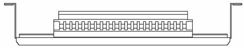
Figure 4-19 Front view of the power distribution box

Figure 4-20 Top view of the power distribution box
![]() Caution:
Caution:
l The power distribution box takes AC high voltage. Do not operate it before breaking its power.
l Make sure the power cord ports are covered with protection tube such that no wire tailpiece is exposed at any joint.
II. Connect power cords to the power distribution box
Use three cables to connect the client power distribution box to the terminal block of the cabinet power distribution box. You are recommended to use the cables with 16 mm2 cross-sectional area (the colors of the cables differ depending on the cable specifications in different countries). Connect the power cords according to the following relations:
l Live wire L in the client power distribution box — Live wire L in the cabinet power distribution box
l Neutral wire N in the client power distribution box — Neutral wire N in the cabinet power distribution box
l Earth wire G in the client power distribution box — Earth wire PE in the cabinet power distribution box
Use 3.5 m (11.5 ft) long cables to connect the cabinet power distribution box to the system power supply and PoE power supply. The three wires of each cable should be respectively connected to the ports L, N and PE of the power distribution box. Make sure the protection tubes are used and no wire tailpiece is exposed during the connection. You should connect power cord 1 to L1, N1 and PE1, power cord 2 to L2, N2 and PE2, and so on. The number of power cords depends on the cabinet configuration. Note that you should connect the brown wire to L (live wire), the blue wire to N (neutral wire), and yellow-green wire to PE (earth wire).
After finishing the connection of the cables, bind these cables in order with cable strap, wire them along the right side of the cabinet down, and connect them to the input ports of the system power supply and PoE power supply. You should make sure the cables are not loose.
III. Installing the power distribution box
You should install the power distribution box on the top of the back of the B68 cabinet. You can adjust the location of the box in a little range.
The following figure describes the cable connections on the cabinet power distribution box.

Figure 4-21 Cable connections on the cabinet power distribution box
4.7 Installing DC Power Distribution Box
4.7.1 Terminal Block
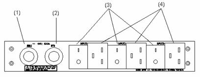
I. Terminal block structure diagram

Figure 4-22 Terminal block structure diagram
As illustrated in Figure 4-22, the two leftmost input terminal blocks are DC input terminal blocks. Next to them are two air switches, each of which has a through-current capacity of 63A. On the rightmost side are 9 terminal blocks, 6 of which are BGND terminal blocks and the rest are PGND terminal blocks.
II. Diagram for connecting terminal blocks

Figure 4-23 Diagram for connecting DC input terminal blocks
III. Electrical capacity of the terminal blocks
l Rated current: 63 A
l Rated voltage: 600 V
l Rated cross-sectional area: 16 mm2
l Maximum current/maximum crimping area: 63 A/16 mm2
IV. Terminal block components
Table 4-1illustrates terminal block components.
Table 4-1 Terminal block components
|
NO |
Name |
Quantity |
|
1 |
End bracket |
2 |
|
2 |
Cross connector |
3 |
|
3 |
Marker |
6 |
|
4 |
Terminal |
11 |
|
5 |
Clapboard |
7 |
|
6 |
Rail |
1 |
|
7 |
Circuit breaker |
6 |
4.7.2 Installation of Power Distribution Box
To install power distribution box, take the following steps:
l Install the DC input terminal blocks and air switches to the cabinet via the rail, as illustrated in Figure 4-24.
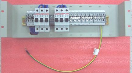
Figure 4-24 Install the DC input terminal blocks and air switches
l Connect the DC input terminal blocks and the air switches with 6mm2 cables and fix the cable properly. Also use a 6mm2 cable for grounding, as illustrated in Figure 4-25.
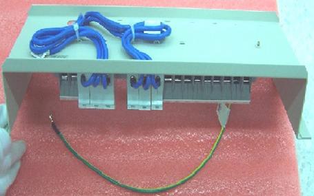
Figure 4-25 Backplane Diagram for connecting DC input terminal blocks and air switches
l Fix the DC power distribution box onto the back of the cabinet, as illustrated in Figure 4-26.
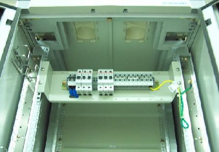
Figure 4-26 Diagram for fixing the power distribution box to the rear of the B68 cabinet
l You can make the air switches to supply power to DC power modules by connecting the lower terminals of the air switches to DC power input terminals and supply voltages to DC power. (Refer to Figure 4-23 for detail. Note that the diameter of the cables need to be 6mm2 or 10mm2.)
l You can use the BGND and PGND terminal blocks as needed. The rightmost PGND terminals must be connected to the cabinet using a 6mm2 cables, as illustrated in Figure 4-26.
l Fasten the connected power cables with a wire and secure them onto the power distribution box.
l
Use two 16mm2 cables ![]() to connect the cabinet and the DC power distribution box. You need
to connect the two cables to the leftmost terminal blocks of the cabinet, as
illustrated in Figure 4-23.
to connect the cabinet and the DC power distribution box. You need
to connect the two cables to the leftmost terminal blocks of the cabinet, as
illustrated in Figure 4-23.
4.8 Installing Cabling Rack
For your convenience, cabling racks are shipped with the S9500 series. Take the following steps to install the rack.
Step 1: Face the LPU slots of the switch;
Step 2: Attach the left mounting ear (the one with an elliptical hole on one surface and a recessed hole on the other) onto the cabling rack and fix it with screws (one cabling rack for S9505/S9508 and two for S9512);
Step 3: Install mounting ears onto the both sides of the switch.

Figure 4-27 The position of the cabling rack
4.9 Installing Fan Tray
The fan tray is hot swappable.
![]() Caution:
Caution:
In case of bodily injuries, do not touch any naked wire, terminal or other parts of the product with hazardous voltage labels.
Step 1: Wear the ESD-preventive wrist strap, making sure that it makes good skin contact; take the fan tray out from the packing bag.
Step 2: Hold the fan tray in right direction (just check the direction of instructional words, and if you insert it upside down, the plug of the fan tray cannot touch the right socket inside the chassis), with one hand on its handle and the other hand at its bottom the ejector levers on the fan tray with both hands and pull them outward. Align the fan tray with the guides in the chassis and slide it gently into the slot until its plug touches the chassis socket.
Step 3: Fasten the mounting screws on the panel of the fan tray with a screw driver.
& Note:
The above installation steps are just for replacing your fan tray, since the fan tray is delivered together with the chassis and no initial installation is required.
4.10 Installing LPU
The LPUs of the S9500 series are hot-swappable.
Step 1: Wear the ESD-preventive wrist strip, making sure that you have grounded it well. Take the LPU out of the packing bag.
Step 2: Unscrew the mounting screws holding the blank filler panel in the slot where you plan to install the LPU, and remove the panel from the slot.
Step 3: Hold the ejector levers on the fan tray with both hands and pull them outward. Align the LPU with the guides in the chassis and slide it gently into the slot until the positioning pin of the LPU touches the hole in the chassis.
Step 4: Pull the ejector levers inward, locking the positioning pin into the hole.
Step 5: Fix the LPU by fastening the mounting screws on the LPU with a screw driver.
& Note:
Put the removed blank filler panel away for future use.
For the S9500 series, the service processor card can be installed in the LPU slot in the same way as installing the LPU board.
4.11 Connecting Interface Cables
4.11.1 Connecting Console Cable
I. Introduction
Console cable is an 8-core shielded cable. At one end of the cable is a crimped RJ-45 connector that is to be plugged into the console port of the switch. At the other end of the cable is a DB-9 (female) connector. You can plug it into the 9-pin (male) serial port on the console terminal. The following figure illustrates the console cable.

Table 4-2 Console cable pinouts
|
RJ-45 |
Signal |
DB-9 |
Signal |
|
1 |
RTS |
8 |
CTS |
|
2 |
DTR |
6 |
DSR |
|
3 |
TXD |
2 |
RXD |
|
4 |
CD |
5 |
SG |
|
5 |
GND |
5 |
SG |
|
6 |
RXD |
3 |
TXD |
|
7 |
DSR |
4 |
DTR |
|
8 |
CTS |
7 |
RTS |
II. Connecting console cable
Take the following steps to connect the console cable, when configuring the switch on the terminal.
1) Plug the DB-9 female connector of the console cable into the serial port of the PC/terminal where the switch is to be configured.
2) Connect the RJ-45 connector of the console cable to the console port of the switch.
& Note:
The PC serial port is not hot-swappable, so you are not allowed to insert or remove the console cable into or from the PC serial port.
When connecting the console cable, first connect the DB9 end to the PC serial port and then the RJ45 end to the console port of the switch. And removing the console cable is just in inverse order.
When removing the console cable, first remove the RJ-45 end and then the DB9 end.
4.11.2 Connecting AUX Cable
You need an AUX cable when configuring the S9500 series with the remote modem dial-up approach.
I. Introduction
AUX cable is an 8-core shielded cable. At one end of the cable is an RS-232-compliant RJ-45 connector that can be plugged into the AUX port of the switch. At the other end is DB-9 (male) connector. You can plug it into the DB-9 (female) port of the modem. For detail, refer to Figure 4-28 and Table 4-2.
II. Connecting AUX cable
1) Plug the RJ-45 connector of the AUX cable into the AUX port of the switch.
Plug the DB-9 (male) connector at the other end into the serial port of the analog modem.
4.11.3 Connecting Category-5 Shielded Cable
I. Introduction to RJ-45 connector

II. Connecting category-5 shielded cable
Step 1: Plug one end of the network cable into the desired Ethernet RJ-45 connector on the switch.
Step 2: Plug the other end of the cable into the RJ-45 port of the peer device.
4.11.4 Connecting Fiber
& Note:
All the megabit and gigabit optical modules available for the S9500 series are SFP modules that provide LC user ports.
I. Introduction to fiber connector
& Note:
l When selecting a fiber network facility, make sure that the type of the connector and the fiber match the adopted optical port.
l Before connecting the fiber, make sure that the receive-end optical power does not exceed the upper threshold of the receiving optical power. Excessive receiving optical power is very likely to burn the optical module.
Fiber connectors are indispensable passive components in an optical fiber communication system. Their application allows the removable connection between optical channels, which makes the optical system debugging and maintenance more convenient and the transit dispatching of the system more flexible. Among various fiber connectors, only LC connector will be introduced here.
l LC fiber connector

II. Connecting fiber
Step 1: Plug one end of the fiber into the SFP optical module of the S9500 series.
Step 2: Connect the other end of the fiber into the corresponding device.
![]() Caution:
Caution:
When the optical interface has not been connected with a fiber connector or its dustproof mesh is open, there might be some invisible radiation emitted from the optical interface. So do not look into the optical interface directly.
Cover the optical interface if there is no connector plugged in.
4.12 Cable Routing Recommendations
4.12.1 Freestanding Switch on Tabletop
For only selling an integrated chassis, you do not have to care about the cabling inside or outside the cabinet. All the LPU cables are routed from the left side of the chassis (along the cabling channel), and the chassis power cords (AC/DC power cords) are routed in the front of the chassis.
4.12.2 Cabinet-Mounting Switch
If the switch is mounted in a 19-inch standard cabinet or B68-22 cabinet, the LPU cables are bound on the cabling rack at the left side of the chassis and are routed up or down to pass through the chassis top or the raised floor depending on the available equipment room condition (that is, the signal cables are routed into the chassis either from the cabling rack on the chassis top or from the cabling trough under the floor) of the exchange office. The power cords run along the left-front of the chassis and out of the chassis either from the top or the raised floor depending on the equipment room conditions (DC power distribution cabinet, lightning protection box, and terminal block, etc.) of the exchange office.
4.13 Cable Management
4.13.1 Correct Labels
Before bundling the cables, you should fill in the labels for them correctly and stick them to the right position on the cables. For details, refer to the description of label usage in Appendix A Engineering Labels for Cables.
4.13.2 Cable Management Requirements
l Bundle and put the cables inside the cabinet in a straight and neat way. No intertwinement or bending is allowed.

Figure 4-31 Cable bundling example I
l The bending radius of cable body cannot be less than twice of the cable diameter. The bending radius of the cable cannot be less than 5 times of its diameter at the place where it is led out of the connector;
l Different cables (power cord, signal cable, PGND wire, etc.) should be cabled and bundled separately rather than together in the cabinet. If they are close to each other, you can cable them in cross-shape. For parallel cabling, the space between power cord and signal cable should be no less than 30 mm (1.2 in);
l The cable binding rack and cabling channel inside and outside the cabinet should be smooth and without sharp edges or tips;
l The metal cable management hole should have a smooth and fully rounded surface or wear a insulating bush;
l Use the right type of ties to bundle the cables. Do not bundle cables with joined ties. The following types of ties are available currently: 100 2.5 mm (3.9 in 0.1 in), 150 3.6 mm (5.9 0.1 in), 300 3.6 mm (11.8 0.1 in), 530 9 mm (20.9 0.4 in), and 580 13 mm (22.8 0.5 in);
l Cut the extra parts of the ties neatly after bundling the cables, leaving no sharp or angular tips. See the following figure:

Figure 4-32 Cable bundling example II
l Bundle the cables wherever cable bending cannot be avoided. However, the cable ties cannot be placed inside the bending area in case of the likelihood of cable core break due to excessive stress. See the following figure.

Figure 4-33 Cable bundling example III
l The spare cables or excessive cable parts should be folded and bundled and placed at a right place in the cabinet or on the cabling channel. A “right place” refers to the place where the cables will not affect the operation of the device or impair the device, or be damaged;
l The power cords cannot be tied on the guides of any mobile components;
l Reserve some redundancy for the cables connecting to the mobile parts, the PGND wire of the door for example, to free the cables from possible stress. Such a mobile part should be installed in such a way that the extra cable segments will be kept from contacting the heat source, sharp points or edges. Use high temperature cables near the heat sources;
l For the cable terminals fixed using screw threads, the screws or nuts should be securely fastened and prevented from loosing. See the following figure;

Figure 4-34 Cable fixing example
l When using a hard power cord, fix it near its terminal so as to free the terminal and the cable from stress;
l Do not use tapping screws to fasten the connecting terminals;
l The power cords of the same type and in the same direction should be bundled together and kept neatly and straight;
The following table lists the requirements in the bundling with cable ties.
Table 4-3 Tie-binding parameters
|
Cable bundle diameter (mm) |
Space between bundles (mm) |
|
10 |
80 to 150 |
|
10 to 30 |
150 to 200 |
|
30 |
200 to 300 |
l No cable or bundle can tie a knot;
l The metal parts of the crimped cold-pressed terminal blocks (such as air switch) cannot stretch beyond the blocks.
4.14 Verifying the Installation
![]() Caution:
Caution:
Confirm that you have turned off the power before checking, otherwise, improper connection will hurt people or impair the components of the switch.
After installing the switch, verify the installation by the following list, ensuring all the checking results are normal.
Table 4-4 Installation checking list
|
Item |
Normal |
Abnormal (Description) |
|
ESD-preventive wrist strap |
|
|
|
Console cable |
|
|
|
PGND wire |
|
|
|
Power cord |
|
|
|
SRPU |
|
|
|
LPU/service processor card |
|
|
|
Fan tray |
|
|
|
PSU |
|
|