- Table of Contents
-
- H3C S9500 Series Routing Switches Installation Manual-(V1.01)
- 00-1Cover
- 01-Chapter1 Product Overview
- 02-Chapter2 LPU Modules
- 03-Chapter3 Installation Preparations
- 04-Chapter4 Switch Installation
- 05-Chapter5 System Debugging
- 06-Chapter6 Switch Monitoring and Maintenance
- 07-AppendixA Engineering Labels for Cables
- 08-AppendixB Installation of B68 Cabinet
- 09-AppendixC Lightning Protection of the Switch
- Related Documents
-
| Title | Size | Download |
|---|---|---|
| 02-Chapter2 LPU Modules | 503 KB |
Table of Contents
Chapter 2 LPU Modules
2.1 Overview
The S9500 series are modular switches that are designed following industry standards. The series can be equipped with these types of LPU modules:
l XP2 module: provides two 10GEBase-R XFP/LC/10GEBase-W XFP/LC optical ports
l XP4 module: provides four 10GE XFP/LC optical ports (1:2 convergence)
l XK1 module: provides one 10 GE XENPAK/SC optical/electrical port
l GP12 module: provides 12 1000 Mbps SFP/LC electrical/optical ports
l GP24 module: provides 24 1000 Mbps SFP/LC optical ports
l FP20 module: provides 20 100 Mbps SFP/LC optical ports
l F32G module: provides four 1000 Mbps SFP/LC optical ports and 32 10/100 Mbps auto-sensing RJ-45 ports
l GT24 module: provides 24 10/100/1000 Mbps auto-sensing RJ-45 ports
l GV48 module: provides 48 10/100/1000 Mbps PoE-capable auto-sensing RJ-45 ports
l FT48 module: provides 48 10/100 Mbps ports
l P4G8 module: provides eight 1000 Mbps SFP/LC optical ports and four 155 Mbps SFP/LC POS optical ports
l SP4 module: provides four OC-48c SFP/LC POS optical ports
l UP1 module: provides one OC-192c XFP/LC POS optical port
2.2 XP2 Module
2.2.1 Specifications
The XP2 module provides two 10GEBase-R XFP/LC/10GEBase-W XFP/LC optical ports.
Table 2-1 XP2 module specifications
|
Attribute |
XP2 |
|
CPU |
MPC8245 |
|
Boot ROM |
512 KB |
|
SDRAM |
128 MB/256MB |
|
Dimensions (L W) |
366.7 340 mm (14.4 13.4 in.) |
|
Max. power consumption |
87 W |
|
Number of ports |
Two |
|
Connector |
XFP/LC |
|
Rate |
10 Gbps |
2.2.2 Panel and LEDs
![]()
The XP2 module has two LEDs for each optical port on its panel.
Table 2-2 1000 Mbps optical port LEDs on the XP2 module
|
LED |
Status |
|
|
LINK |
OFF |
No link is present. |
|
Green |
A link is present. |
|
|
ACT |
OFF |
No packets are transmitted/received on the port. |
|
Orange blinking |
Packets are being transmitted/received on the port. |
|
2.2.3 Matching Cable
The XP2 module provides two 10 Gbps XFP optical ports. To provide optical ports, you can use these XFP optical modules.
Table 2-3 Optical interface modules available for the XP2 module
|
SFP module |
Central wavelength |
Connector |
Matching cable |
Transmission distance |
|
10GBase-SR/SW-XFP |
850 nm |
LC |
50/125 m multimode optical fiber cable |
26 m (85.3 ft) for the 62.5 m MMF w/ 160MHz*km cable; 82 m (269.0 ft) for the 50 m MMF w/ 500MHz*km cable; 300 m (984.3 ft) for the 50 m MMF w/ 2000MHz*km cable |
|
10GBase-LR/LW-XFP |
1310 nm |
9/125 m single mode optical fiber cable |
10 km (6 mi) |
|
|
10GBase-ER/EW-XFP |
1550 nm |
9/125 m single mode optical fiber cable |
40 km (25 mi) |
2.3 XP4 Module
2.3.1 Specifications
The XP4 module provides four 10GE XFP/LC optical ports (1:2 convergence).
Table 2-4 XP4 module specifications
|
Attribute |
XP2 |
|
CPU |
MPC8245 |
|
Boot ROM |
512 KB |
|
SDRAM |
128 MB/256MB |
|
Dimensions (L W) |
366.7 340 mm (14.4 13.4 in.) |
|
Number of ports |
Four |
|
Max. power consumption (with bottom plate) |
160 W |
|
Connector |
XFP/LC |
|
Rate |
10 Gbps |
2.3.2 Panel and LEDs

The XP4 module has two LEDs for each optical port on its panel.
Table 2-5 1000 Mbps optical port LEDs on the XP4 module
|
LED |
Status |
|
|
LINK |
OFF |
No link is present. |
|
Green |
A link is present. |
|
|
ACT |
OFF |
No packets are transmitted/received on the port. |
|
Orange blinking |
Packets are being transmitted/received on the port. |
|
2.3.3 Matching Cable
The XP4 module provides four 10 Gbps XFP optical ports. For more details about XFP optical modules, see Table 2-3.
2.4 XK1 Module
2.4.1 Specifications
The XK1 module provides one 10GE XENPAK/SC optical/electrical port.
Table 2-6 XK1 module specifications
|
Attribute |
XK1 |
|
CPU |
MPC8245 |
|
Boot ROM |
512 KB |
|
SDRAM |
128 MB/256 MB |
|
Dimensions (L W) |
366.7 340 mm(14.4 13.4 in.) |
|
Max. power consumption |
45 W |
|
Number of ports |
One |
|
Connector |
XENPAK/SC |
|
Rate |
10 Gbps |
2.4.2 Panel and LEDs

The XK1 module has two port LEDs for the 10GE port on its panel.
Table 2-7 Port LEDs on the XK1 module
|
LED |
Status |
|
|
LINK |
OFF |
No link is present. |
|
Green ON |
A link is present. |
|
|
ACT |
OFF |
No packets are transmitted/received on the port. |
|
Orange blinking |
Packets are being transmitted/received on the port. |
|
2.4.3 Matching Cable
The XK1 module provides one 10GE XENPAK/SC optical or electrical port. You can use these XENPAK optical modules.
Table 2-8 Interface modules available for the XK1 module
|
SFP module |
Central wavelength |
Connector |
Matching cable |
Transmission distance |
|
10GBASE-SR-XENPAK |
850 nm |
SC |
Multimode optical fiber cable |
26 m (85.3 ft) for the 62.5 m MMF w/ 160MHz*km cable; 82 m (269.0 ft) for the 50 m MMF w/ 500MHz*km cable; 300 m (984.3 ft) for the 50 m MMF w/ 2000MHz*km cable |
|
10GBASE-LR-XENPAK |
1310 nm |
Single mode optical fiber cable |
10 km (6 mi) |
|
|
10GBASE-ER-XENPAK |
1550 nm |
40 km (25 mi) |
||
|
80 km (50 mi) |
2.5 GP12 Module
2.5.1 Specifications
The GP12 module provides 12 1000 Mbps SFP/LC optical ports.
Table 2-9 GP12 module specifications
|
Attribute |
GP12 |
|
CPU |
MPC8245 |
|
Boot ROM` |
512 KB |
|
SDRAM |
128 MB/256 MB |
|
Dimensions (L W) |
366.7 340 mm (14.4 13.4 in.) |
|
Max. power consumption |
55 W |
|
Number of ports |
12 |
|
Connector |
SFP/LC |
|
Rate |
1000 Mbps |
2.5.2 Panel and LEDs

The GP12 module has two LEDs for each port on its panel.
Table 2-10 Port LEDs on the GP12 module
|
LED |
Status |
|
|
LINK |
OFF |
No link is present. |
|
Green |
A link is present. |
|
|
ACT |
OFF |
No packets are transmitted/received on the port. |
|
Orange blinking |
Packets are being transmitted/received on the port. |
|
2.5.3 Matching Cable
The GP12 module can provide 12 1000 Mbps optical ports. You can use these SFP optical modules:
Table 2-11 Interface modules available for the GP12 module
|
SFP module |
Central wavelength |
Connector |
Matching cable |
Transmission distance |
|
1000BASE-SX-SFP |
850 nm |
LC |
50/125 m multimode optical fiber cable |
550 m (1804 ft) |
|
62.5/125 m multimode optical fiber cable |
275 m (902 ft) |
|||
|
1000BASE-LX-SFP |
1310 nm |
9/125 m single mode optical fiber cable |
10 km (6 mi) |
|
|
1000BASE-LH-SFP |
40 km (25 mi) |
|||
|
1000BASE-ZX-LR- SFP |
1550 nm |
|||
|
1000BASE-ZX-VR-SFP |
70 km (43 mi) |
|||
|
1000BASE-ZX-UR-SFP |
100km (62 mi) |
2.6 GP24 Module
2.6.1 Specifications
The GP24 module provides 24 1000 Mbps SFP/LC optical ports.
Table 2-12 GP24 module specifications
|
Attribute |
GP24 |
|
CPU |
MPC8245 |
|
Boot ROM |
512 KB |
|
SDRAM |
128 MB/256MB |
|
Dimensions (L W) |
366.7 340 mm (14.4 13.4 in.) |
|
Max. power consumption |
100 W |
|
Number of ports |
24 |
|
Connector |
SFP/LC |
|
Rate |
1000 Mbps |
2.6.2 Panel and LEDs

The GP24 module has two LEDs for each 1000 Mbps optical port on its panel.
Table 2-13 Port LEDs on the GP24 module
|
LED |
Status |
|
|
LINK |
OFF |
No link is present. |
|
Green |
A link is present. |
|
|
ACT |
OFF |
No packets are transmitted/received on the port. |
|
Orange blinking |
Packets are being transmitted/received on the port. |
|
2.6.3 Matching Cable
The GP24 module provides 24 1000 Mbps optical ports. For more details about SFP optical modules, see Table 2-11
2.7 FP20 Module
2.7.1 Specifications
The FP20 module provides 20 100 Mbps SFP/LC optical ports.
Table 2-14 FP20 module specifications
|
Attribute |
FP20 |
|
CPU |
MPC8245 |
|
Boot ROM |
512 KB |
|
SDRAM |
128 MB/256 MB |
|
Dimensions (L W) |
366.7 340 mm (14.4 13.4 in.) |
|
Max. power consumption |
50W |
|
Port |
20 |
|
Connector |
SFP/LC |
|
Rate |
100 Mbps full duplex |
2.7.2 Panel and LEDs

The FP20 module has two LEDs for each port on its panel.
Table 2-15 Port LEDs on FP20 module
|
LED |
Status |
|
|
LINK |
OFF |
No link is present. |
|
Green |
A link is present. |
|
|
ACT |
OFF |
No packets are transmitted/received on the port. |
|
Orange blinking |
Packets are being transmitted/received on the port. |
|
2.7.3 Matching Cable
The FP20 module provides 20 100 Mbps SFP optical ports. You can use these SFP optical modules:
Table 2-16 Interface modules available for the FP20 module
|
SFP module |
Central wavelength |
Connector |
Matching cable |
Transmission distance |
|
100BASE-FX-MM-SFP |
1310 nm |
LC |
50/125 m multimode optical fiber cable |
2 km (1 mi) |
|
62.5/125 m multimode optical fiber cable |
||||
|
100BASE-FX-SM-SFP |
9/125 m single mode optical fiber |
15 km (9 mi) |
||
|
100BASE-FX-SM-LR-SFP |
40 km (25 mi) |
|||
|
100BASE-FX-SM-VR-SFP |
1550 nm |
80 km (50 mi) |
2.8 F32G Module
2.8.1 Specifications
The F32G module provides four 1000 Mbps SFP/LC optical ports and 32 x 10/100 Mbps auto-sensing RJ-45 ports.
Table 2-17 F32G module specifications
|
Attribute |
F32G |
|
CPU |
MPC8245 |
|
Boot ROM |
512 KB |
|
SDRAM |
128 MB/256 MB |
|
Dimensions (L W) |
366.7 340 mm (14.4 13.4 in.) |
|
Max. power consumption |
55 W |
|
Number of ports |
Four 1000 Mbps SFP/LC optical ports 32 x 10/100 Mbps auto-sensing RJ-45 ports |
|
Connector |
RJ-45, SFP/LC |
|
Rate |
10 Mbps, half/full duplex 100 Mbps, half/full duplex 1000 Mbps, full duplex |
2.8.2 Panel and LEDs
The F32G module has two LEDs for each 1000 Mbps port on its panel.
Table 2-18 1000 Mbps port LEDs on the F32G module
|
LED |
Status |
|
|
LINK |
OFF |
No link is present. |
|
Green |
A link is present. |
|
|
ACT |
OFF |
No packets are transmitted/received on the port. |
|
Orange blinking |
Packets are being transmitted/received on the port. |
|
The F32G module has one LED for each 100 Mbps port on its panel.
Table 2-19 100 Mbps port LEDs on F32G module
|
LED |
Status |
|
|
LINK/ACT |
ON |
A link is present on the port. |
|
OFF |
No link is present on the port. |
|
|
Blinking |
Packets are being transmitted/received on the port. |
|
2.8.3 Matching Cable
The F32G can provide four 1000 Mbps SFP optical ports. For more details about the SFP modules, see Table 2-11.
The 32 10/100 Mbps electrical ports on the F32G module use RJ-45 connectors and category-5 twisted pair cables which allow the transmission distance of 100 m (328 ft).

Table 2-20 Pin assignment of the RJ-45 MDI connector
|
Pin No. |
10Base-T/100Base-TX |
|
|
Signal |
Function |
|
|
1 |
Tx+ |
Transmit data. |
|
2 |
Tx- |
Transmit data. |
|
3 |
Rx+ |
Receive data. |
|
4 |
Reserved |
- |
|
5 |
Reserved |
- |
|
6 |
Rx- |
Receive data. |
|
7 |
Reserved |
- |
|
8 |
Reserved |
- |
Table 2-21 Pin assignment of the RJ-45 MDI-X connector
|
Pin No. |
10Base-T/100Base-TX |
|
|
Signal |
Function |
|
|
1 |
Rx+ |
Receive data. |
|
2 |
Rx- |
Receive data. |
|
3 |
Tx+ |
Transmit data. |
|
4 |
Reserved |
- |
|
5 |
Reserved |
- |
|
6 |
Tx- |
Transmit data. |
|
7 |
Reserved |
- |
|
8 |
Reserved |
- |
& Note:
Tx = Transmit data; Rx = Receive data
2.9 GT24 Module
2.9.1 Specifications
The GT24 module provides 24 10/100/1000 Mbps auto-sensing RJ-45 ports.
Table 2-22 GT24 module specifications
|
Attribute |
GT24 |
|
CPU |
MPC8245 |
|
Boot ROM |
512 KB |
|
SDRAM |
128 MB/256 MB |
|
Dimensions (L W) |
366.7 340 mm (14.4 13.4 in.) |
|
Max. power consumption |
110 W |
|
Number of ports |
24 |
|
Connector |
RJ-45 |
|
Rate |
10/100/1000 Mbps |
2.9.2 Panel and LEDs

The GT24 module has one LEDs for each port on its panel.
Table 2-23 Port LEDs on the GT24 module
|
LED |
Status |
|
|
LINK/ACT |
ON |
No link is present. |
|
OFF |
A link is present. |
|
|
Blinking |
Packets are being transmitted/received on the port. |
|
2.9.3 Matching Cable
The ports on the GT24 module uses RJ-45 connectors (see Table 2-24) and category-5 twisted pair cables which allow the transmission distance of 100 m (328 ft).
Figure 2-10 RJ-45 connector
Table 2-24 Pin assignment of the RJ-45 GE connector
|
Pin No. |
10Base-T/100Base-T/1000Base-TX |
|
|
Signal |
Function |
|
|
1 |
MX_0+ |
Transmit and receive data. |
|
2 |
MX_0- |
Transmit and receive data. |
|
3 |
MX_1+ |
Transmit and receive data. |
|
4 |
MX_2+ |
Transmit and receive data. |
|
5 |
MX_2- |
Transmit and receive data. |
|
6 |
MX_1- |
Transmit and receive data. |
|
7 |
MX_3+ |
Transmit and receive data. |
|
8 |
MX_3- |
Transmit and receive data. |
2.10 GV48 Module
2.10.1 Specifications
The GV48 module provides 48 x 10/100/1000 Mbps auto-sensing PoE-capable RJ-45 ports.
Table 2-25 GV48 module specifications
|
Attribute |
GV48 |
|
CPU |
MPC8245 |
|
BootROM |
512 KB |
|
SDRAM |
256 MB |
|
Dimensions (L W) |
366.7 340 mm (14.4 13.4 in.) |
|
Number of ports |
48 |
|
Connector |
RJ-45 |
|
Rate |
10/100/1000 Mbps |
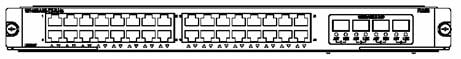
2.10.2 Panel and LEDs
![]()
The GV48 module has one LED for each port on its panel.
Table 2-26 1000 Mbps electrical port LEDs on the GV48 module
|
LED |
Status |
|
|
LINK/ACT |
ON |
A link is present. |
|
OFF |
No link is present. |
|
|
Blinking |
Packets are being transmitted/received on the port. |
|
2.10.3 Matching Cable
For more details, see section 2.9.3 Matching Cable
2.11 FT48 Module
2.11.1 Specifications
The FT48 module provides 48 x 10/100 Mbps auto-sensing RJ-45 ports.
Table 2-27 FT48 module specifications
|
Attribute |
FT48 |
|
CPU |
MPC8245 |
|
Boot ROM |
512 KB |
|
SDRAM |
128 MB/256 MB |
|
Dimensions (L W) |
366.7 340 mm (14.4 13.4 in.) |
|
Max. power consumption |
55 W |
|
Port |
48 |
|
Connector |
RJ-45 |
|
Rate |
10 Mbps, half/full duplex 100 Mbps, half/full duplex |
2.11.2 Panel and LEDs

The FT48 module has one LED for each port on its panel.
Table 2-28 Port LEDs on FT48 module
|
LED |
Status |
|
|
LINK/ACT |
ON |
A link is present. |
|
OFF |
No link is present. |
|
|
Blinking |
Packets are being transmitted/received on the port. |
|
2.11.3 Matching Cable
The FT48 module uses RJ-45 connectors and category-5 twisted pair cables which allow the transmission distance of 100 m.

Table 2-29 Pin assignment of the RJ-45 MDI connector
|
Pin No. |
10Base-T/100Base-TX |
|
|
Signal |
Functionality |
|
|
1 |
Tx+ |
Transmit data. |
|
2 |
Tx- |
Transmit data. |
|
3 |
Rx+ |
Receive data. |
|
4 |
Reserved |
- |
|
5 |
Reserved |
- |
|
6 |
Rx- |
Receive data. |
|
7 |
Reserved |
- |
|
8 |
Reserved |
- |
Table 2-30 Pin assignment of RJ-45 MDI-X connector
|
Pin No. |
10Base-T/100Base-TX |
|
|
Signal |
Functionality |
|
|
1 |
Rx+ |
Receive data. |
|
2 |
Rx- |
Receive data. |
|
3 |
Tx+ |
Transmit data. |
|
4 |
Reserved |
- |
|
5 |
Reserved |
- |
|
6 |
Tx- |
Transmit data. |
|
7 |
Reserved |
- |
|
8 |
Reserved |
- |
& Note:
Tx = Transmit data; Rx = Receive data
2.12 P4G8 Module
2.12.1 Specifications
The P4G8 module provides eight 1000 Mbps SFP/LC optical ports and four OC-3c-POS optical ports.
Table 2-31 P4G8 module specifications
|
Attribute |
P4G8 |
|
CPU |
MPC8245 |
|
Boot ROM |
512 KB |
|
SDRAM |
128 MB/256 MB |
|
Dimensions (L W) |
366.7 340 mm (14.4 13.4 in) |
|
Max. power consumption |
55 W |
|
Number of ports |
Eight 1000 Mbps SFP/LC optical ports Four OC-3c-POS optical ports. |
|
Connector |
SFP/LC |
|
Rate |
1000 Mbps 155 Mbps |
2.12.2 Panel and LEDs

Figure 2-14 P4G8 module panel
The P4G8 module has two LEDs for each port on its panel.
Table 2-32 1000 Mbps port LEDs on the P4G8 module
|
LED |
Status |
|
|
LINK |
OFF |
No link is present. |
|
Green |
A link is present. |
|
|
ACT |
OFF |
No packets are transmitted/received on the port. |
|
Orange blinking |
Packets are being transmitted/received on the port. |
|
Table 2-33 POS port LEDs on the P4G8 module
|
LED |
Status |
|
|
ALM |
OFF |
The link is normal. |
|
ON |
No link is present or the link is faulty. |
|
|
ACT |
OFF |
No packets are transmitted/received on the port. |
|
ON |
Packets are being transmitted/received on the port. |
|
2.12.3 Matching Cable
The GP24 module provides eight 1000 Mbps SFP optical ports. For more details about SFP optical modules, see Table 2-11.
The GP24 module also provides four OC-3c-POS optical ports. For more details about 100 Mbps SFP optical modules (to provide OC-3c-POS optical ports), see Table 2-16.
2.13 SP4 Module
2.13.1 Specifications
The SP4 module provides four OC-48c-POS optical ports.
Table 2-34 SP4 module specifications
|
Attribute |
SP4 |
|
CPU |
MPC8245 |
|
BootROM |
512 KB |
|
SDRAM |
256 MB |
|
Dimensions (L W) |
366.7 340 mm (14.4 13.4 in) |
|
Max. power consumption |
97 W |
|
Number of ports |
Four |
|
Connector |
SFP/LC |
|
Rate |
2.5 Gbps |
2.13.2 Panel and LEDs

The SP4 module has two LEDs for each port on its panel.
Table 2-35 POS port LEDs for the SP4 module
|
LED |
Status |
|
|
ALM |
OFF |
No link is present. |
|
Green |
A link is present. |
|
|
ACT |
OFF |
No packets are transmitted/received on the port. |
|
Orange blinking |
Packets are being transmitted/received on the port. |
|
2.13.3 Matching Cable
The SP4 module provides four OC-48c-POS optical ports. To provide optical ports, you can use these SFP optical modules.
Table 2-36 Optical port modules available for the SP4 module
|
SFP module |
Central wavelength |
Connector |
Matching cable |
Transmission distance |
|
2.5GBASE-FX-MM-SFP |
1310 nm |
LC |
50/125 m multimode optical fiber cable |
2 km (1 mi) |
|
62.5/125 m multimode optical fiber cable |
||||
|
2.5GBASE-FX-SM-SFP |
9/125 m single mode optical fiber cable |
15 km (9 mi) |
||
|
2.5GBASE-FX-SM-LR-SFP |
40 km (25 mi) |
|||
|
2.5GBASE-FX-SM-VR-SFP |
1550 nm |
80 km (50 mi) |
2.14 UP1 Module
2.14.1 Specifications
The UP1 module provides one OC-192c XFP/LC POS optical ports.
Table 2-37 UP1 module specifications
|
Attribute |
UP1 |
|
CPU |
MPC8245 |
|
Boot ROM |
512 KB |
|
SDRAM |
256 MB |
|
Dimensions (L W) |
366.7 340 mm (14.4 13.4 in) |
|
Max. power consumption |
92 W |
|
Number of ports |
One |
|
Connector |
XFP/LC |
|
Rate |
10 Gbps |
2.14.2 Panel and LEDs

The UP1 module has two LEDs for each port on its panel.
|
LED |
Status |
|
|
ALM |
OFF |
The link is normal. |
|
ON |
No link is present or the link is faulty. |
|
|
ACT |
OFF |
No packets are transmitted/received on the port. |
|
ON |
Packets are being transmitted/received on the port. |
|
2.14.3 Matching Cable
The UP1 module provides one OC-192c XFP/LC POS optical port. For more details about XFP optical modules (to provide 10 Gbps POS optical ports), see Table 2-3.