| Title | Size | Downloads |
|---|---|---|
| H3C Campus Switches SmartMC Best Practices-6W100-book.pdf | 1.85 MB |
- Table of Contents
- Related Documents
-
|
|
|
H3C Campus Switches SmartMC Best Practices |
|
|
|
|
|
|
Copyright © 2020 New H3C Technologies Co., Ltd. All rights reserved.
No part of this manual may be reproduced or transmitted in any form or by any means without prior written consent of New H3C Technologies Co., Ltd.
Except for the trademarks of New H3C Technologies Co., Ltd., any trademarks that may be mentioned in this document are the property of their respective owners.
The information in this document is subject to change without notice.
Contents
Configuring automatic deployment
Configuring unified wired and wireless maintenance
Configuring basic WLAN settings
Viewing the network topology and device details
Viewing cameras in the topology
Configuring audio and video monitoring
Viewing audio and video monitoring information
SmartMC feature specifications
SmartMC restrictions and guidelines
Recommended devices for SmartMC
About SmartMC
Background
The expansion of networks requires an increasing number of access devices at network edges. Managing and maintaining such access devices can be very difficult and time-consuming.
Smart Management Center (SmartMC) provides a network management platform that integrates abundant management and maintenance functions for dispersed network devices at network edges, enabling simplified bulk device management.
With SmartMC configured, you can log in to the SmartMC management platform and centrally manage and maintain dispersed network devices at network edges in bulk from the Web interface.
Operating mechanism
Network framework
Figure 1 shows the basic framework of a SmartMC network. The SmartMC network contains the following elements:
· Commander—Manages all members in the SmartMC network. In a SmartMC network, only one device acts as the commander and the remaining devices all act as members.
· Member—Managed by the commander. A SmartMC network can contain a maximum of 64 members.
· File server—Stores startup software images and configuration files for the commander and members. Members obtain the required files from the server according to commands issued by the commander. The file server can be an independent server or co-located with the commander or a member. As a best practice to reduce workloads on the commander or member, deploy an independent file server.
Figure 1 SmartMC network framework

Management platform
The SmartMC management platform integrates the following functions:
· Intelligent management—Includes device role changing, network topology collection, outbound interface configuration, and automated Ethernet link aggregation.
· Intelligent operation and maintenance—Includes member upgrade, bulk backup of configuration files, one-key VLAN deployment, smart port identification, resource monitoring, and faulty device replacement.
· Visibility—Includes network topology management, member adding, device list display, and device state display.
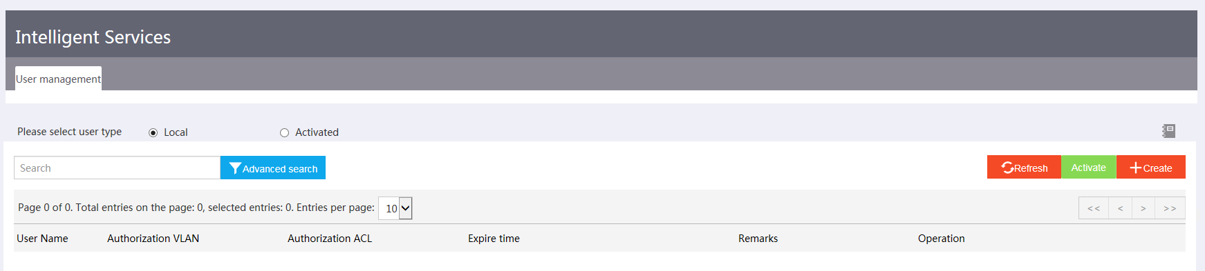
· Intelligent servicing—Includes user creation and activation.
With the SmartMC management platform, you can manage the SmartMC network topology and manage members in bulk.
Figure 2 through Figure 5 show example Web interfaces.
Figure 2 Intelligent management
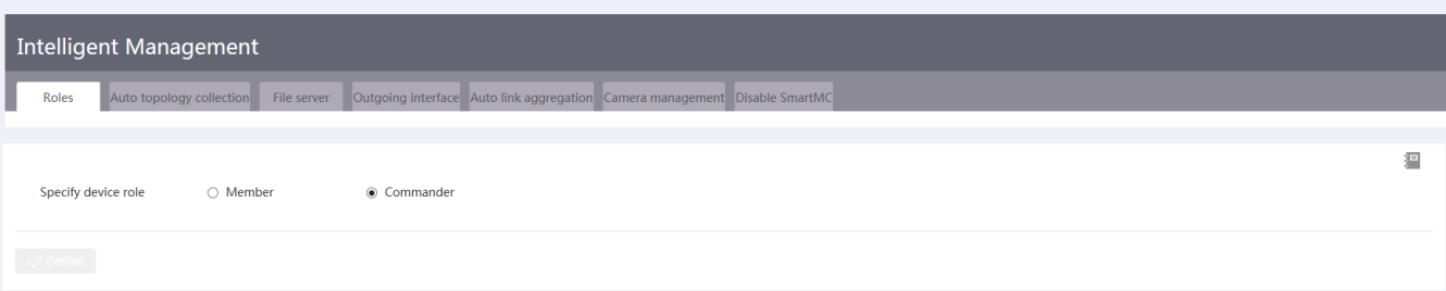
Figure 3 Intelligent operation and maintenance
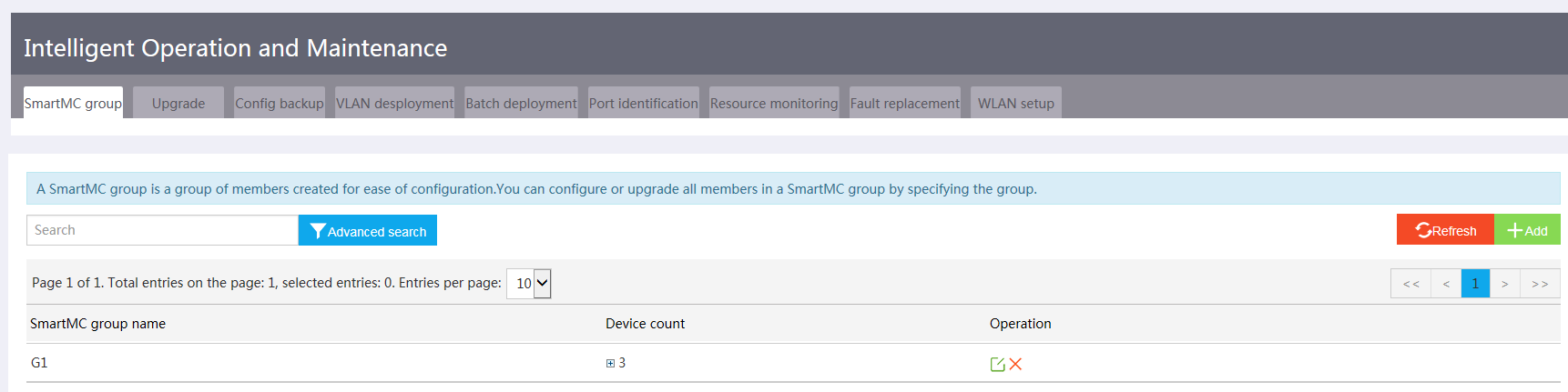
Figure 4 Visibility
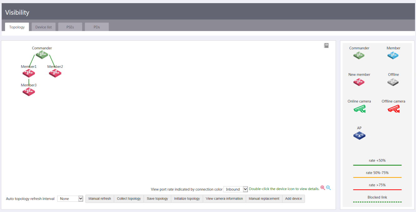
Figure 5 Intelligent servicing
Best practice configuration
Network requirements
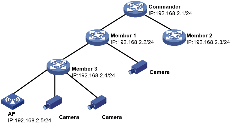
As shown in Figure 6, an AP is connected to member 3, two cameras are connected to member 3, and one camera is connected to member 1. Configure the commander in the SmartMC configuration wizard.
· Configure the members to automatically join the SmartMC network or manually add the members to the network.
· Configure the AP, the commander, and members to communicate with each other in VLAN 1.
· Enable AC functions on the commander and configure member 3 to supply power to the AP and the cameras through PoE.
· Enable SIP-based SQA on all the members to monitor audio and video sessions.
Deploying the SmartMC network
You can configure the members to join the network automatically or add them manually.
Configuring automatic deployment
Procedure
1. Configure the commander:
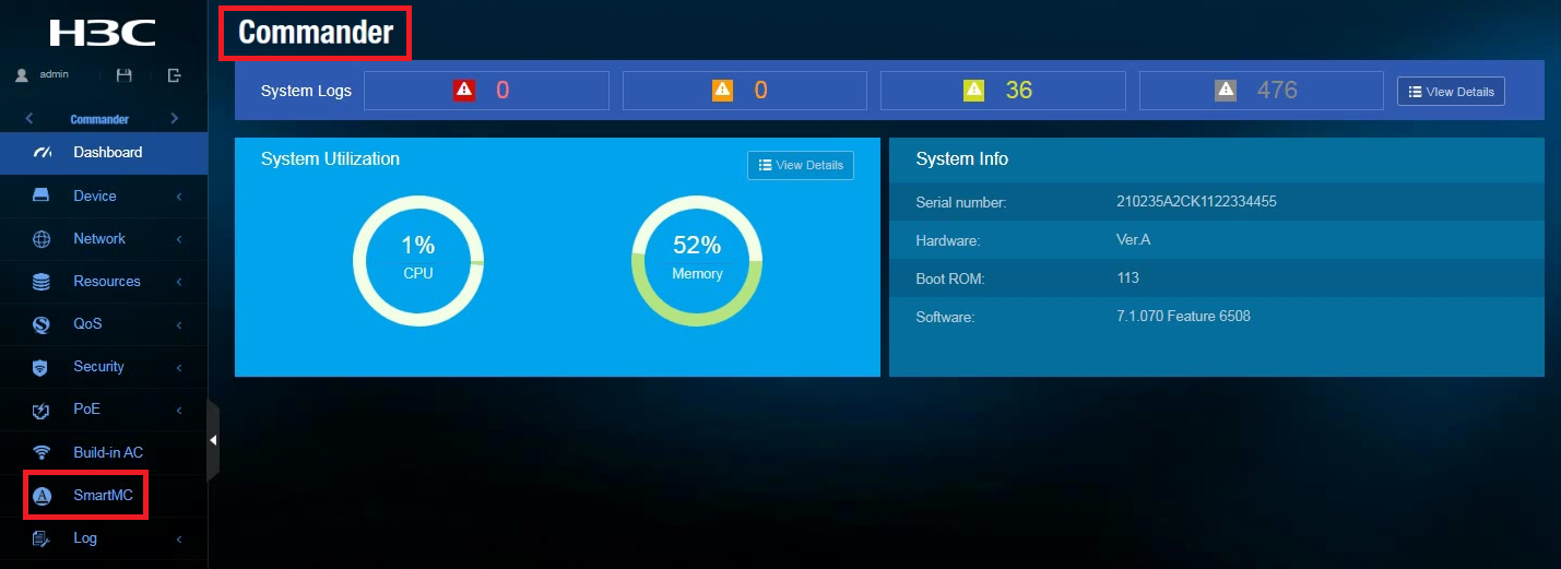
a. Log in to the commander and then click SmartMC from the left navigation pane.
Figure 7 SmartMC Web interface
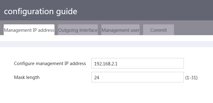
b. Specify the management IP address (IP address of VLAN-interface 1 on the commander).
Figure 8 Specifying the management IP address
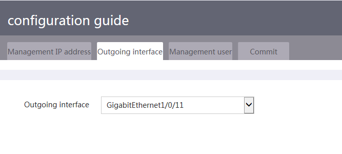
c. Specify the outgoing interface. Specify the interface on the commander that connects the commander to the current PC as the outgoing interface.
Figure 9 Specifying the outgoing interface
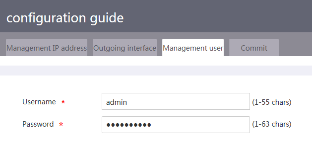
d. Specify the local user of the commander. You can specify an existing local user or a new local user. If you specify a new user, the system creates the user automatically.
Figure 10 Specifying the management user
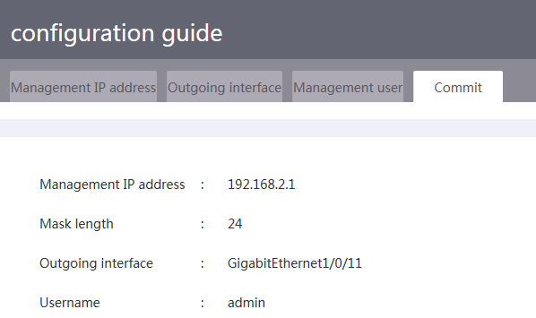
e. Verify the commander settings.
Figure 11 Verifying the commander settings
2. Power on the members without loading any configuration. The members will join the SmartMC network automatically.
Verifying the configuration
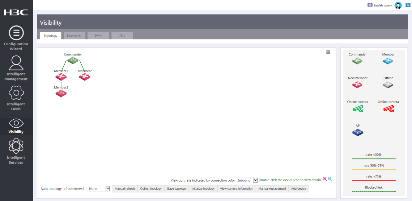
Access the Visibility > Topology page and view the network topology. Verify that members have joined the network as expected.
Figure 12 Network topology
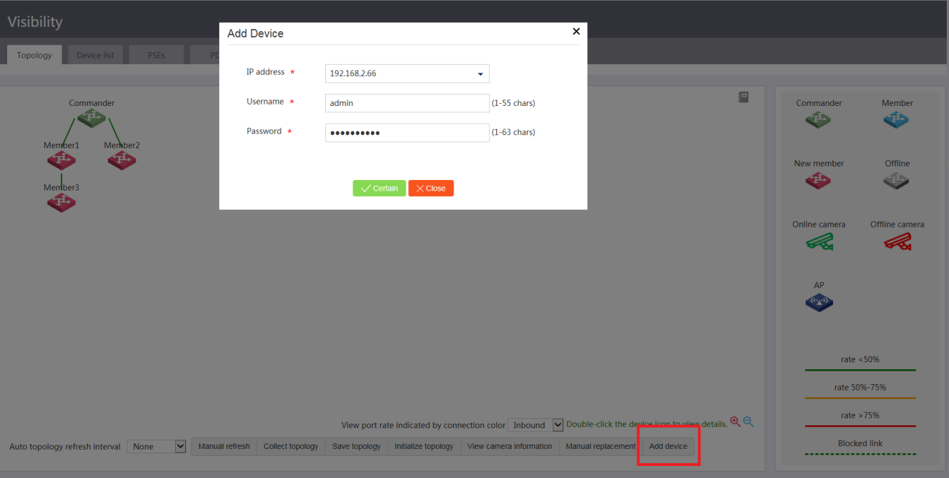
Configuring manual deployment
For members that cannot join the network automatically, you can access the Visibility > Topology page and click Add device to manually add them one by one.
Before a manual adding, make sure the settings in Table 1 have been configured on the member to add.
Table 1 Required settings on members to add manually
|
Item |
Commands |
|
Specify an IP address for VLAN-interface 1. Make sure the IP address is in the same subnet as the IP address of VLAN-interface 1 on the commander. |
· interface vlan-interface 1 · ip address ip-address { mask-length | mask } |
|
Enable HTTP and HTTPS. |
· ip http enable · ip https enable |
|
Enable the Telnet service. |
telnet server enable |
|
Enable NETCONF over SOAP over HTTP. |
netconf soap http enable |
|
Enable LLDP globally. |
lldp global enable |
|
Create a user. Set the username and password to admin, add the telnet, http, and https service types, and authorize the user to use the network-admin user role. |
· local-user admin · password simple admin · service-type telnet http https · authorization-attribute user-role network-admin |
|
Set scheme authentication for VTY user lines 0 to 63. |
· line vty 0 63 · authentication-mode scheme |
|
Enable SNMPv2c and create read-only community public. |
· snmp-agent sys-info version v2c · snmp-agent community read public |
Figure 13 Manually adding a member
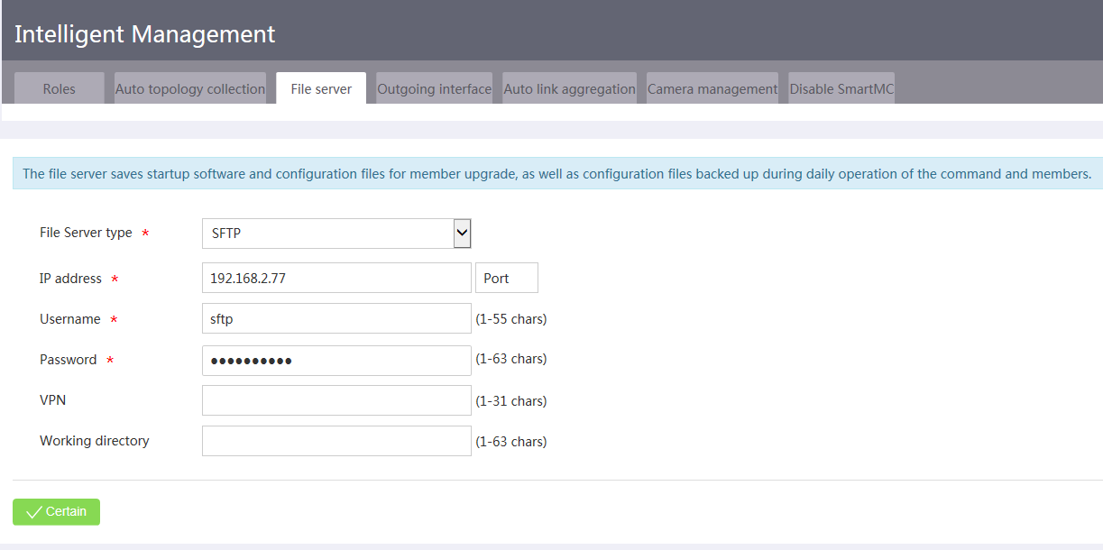
Specifying a file server
A file server is required for fault member replacement, device upgrade, bulk configuration file backup, and bulk configuration deployment.
To specify a file server, access the Intelligent Management > File server page and specify the file server parameters as needed.
Figure 14 Specifying a file server
Configuring unified wired and wireless maintenance
Unified wired and wireless maintenance integrates wired network management, basic wireless network management, and PoE power visibility functions, allowing unified management and statistics displaying for both the wired and wireless networks.
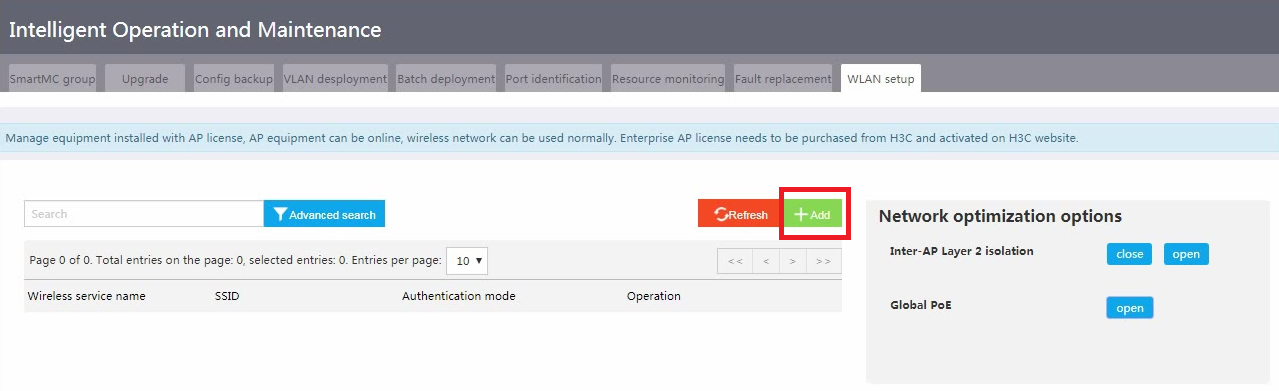
Configuring basic WLAN settings
Perform this task to add, delete, or modify wireless services, configure inter-AP Layer 2 isolation, and manage PoE power supply on all devices in the SmartMC network.
Prerequisites
Make sure the AC function is enabled on the commander.
Restrictions and guidelines
By default, the authentication mode is PSK for created wireless services.
Procedure
1. Access the Intelligent O&M > WLAN setup page.
2. Click Add.
Figure 15 Adding a wireless service
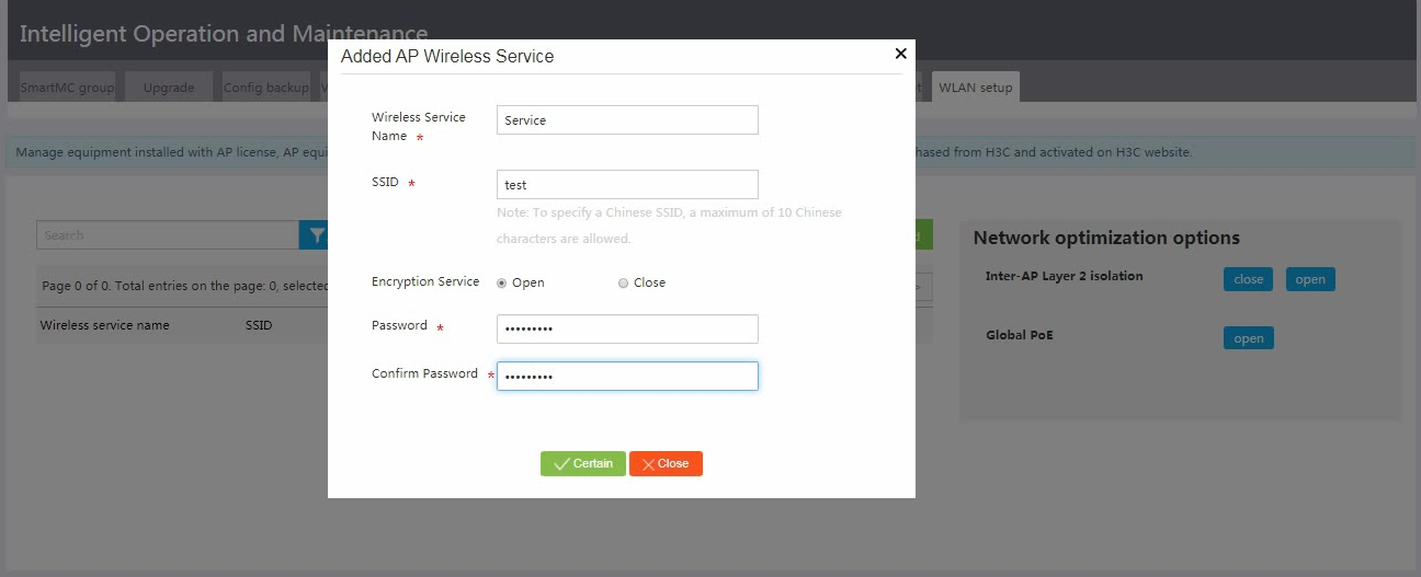
3. Configure wireless service parameters and then click Confirm.
Figure 16 Configuring wireless service parameters
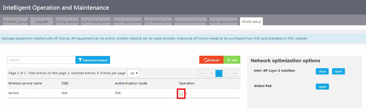
4. Click the Edit icon for the wireless service.
Figure 17 Editing a wireless service
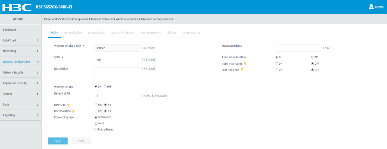
5. Configure advanced wireless service settings as needed.
Figure 18 Configuring advanced wireless service settings
Configuring PoE power supply
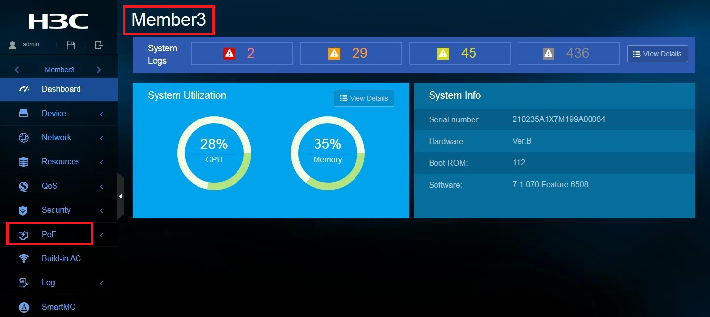
1. From the left navigation pane, click Visibility.
2. To view PSE information, click the PSEs tab. You can click an action link in the Actions column to view PSE details or PDs, or configure PoE power supply.
Figure 19 Viewing PSE information
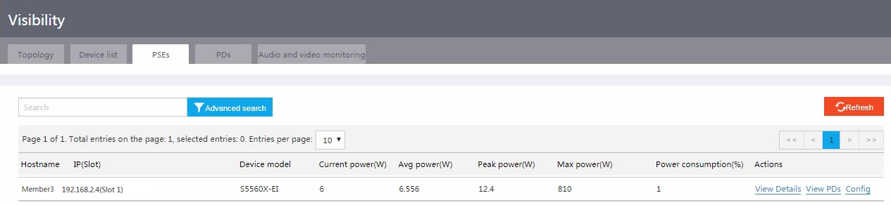
Figure 20 Viewing PSE details
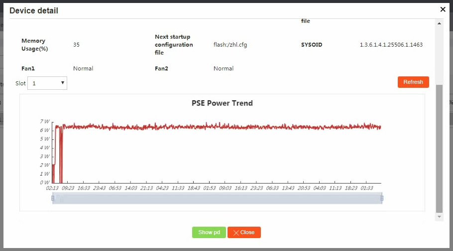
Figure 21 Configuring PoE power supply
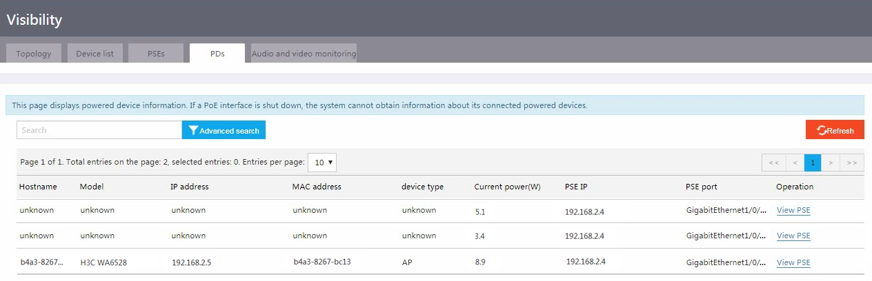
3. To view PD information, click the PDs tab.
Figure 22 Viewing PD information
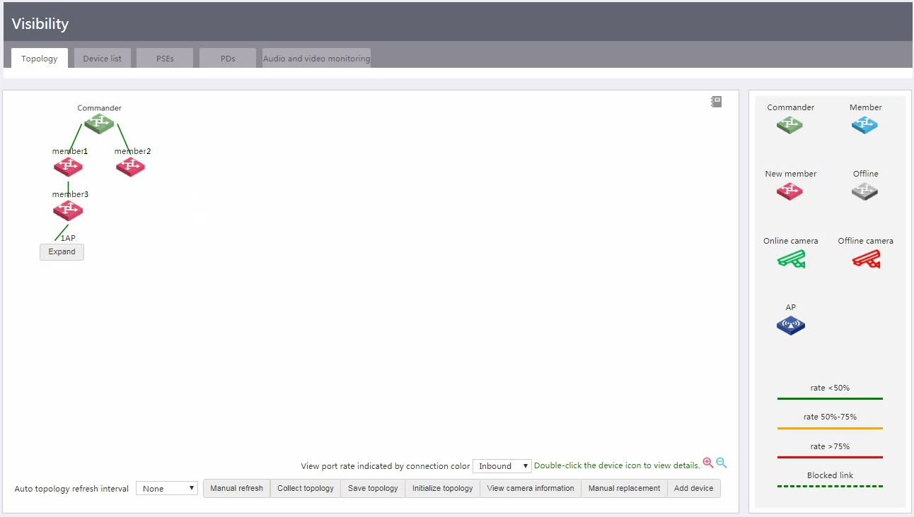
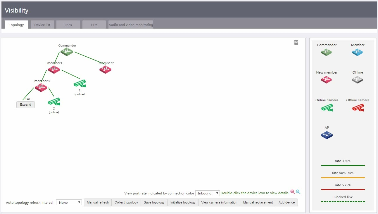
Viewing the network topology and device details
You can view the network topology on the Visibility > Topology page.
To view details information about an AP, click Expand.
To view neighbor information about a device, double click the device icon.
Figure 23 Viewing the network topology and device details
Configuring camera monitoring
Perform this task to monitor the association and disassociation of cameras in VLANs. With this feature configured, the system displays monitored cameras on the Visibility > Topology page and refreshes camera status in real time.
Managing cameras
You can manage a single camera or manage multiple cameras in one operation.
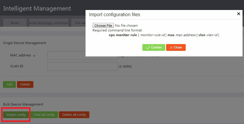
Adding cameras to monitor
To add a single camera, specify the MAC address of the camera and the VLAN in which the camera will be monitored, and then click Add.
To add multiple cameras in bulk, click Import config, and then import a configuration file that contains camera information.
Figure 24 Import cameras to monitor
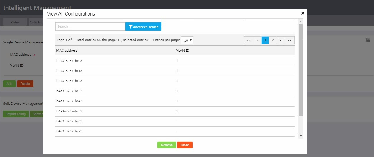
Viewing all monitored cameras
To view all camera monitoring configurations, click View all config.
Figure 25 Viewing all camera monitoring configurations
Deleting cameras
You can delete a camera or multiple cameras in bulk. (Details not shown.)
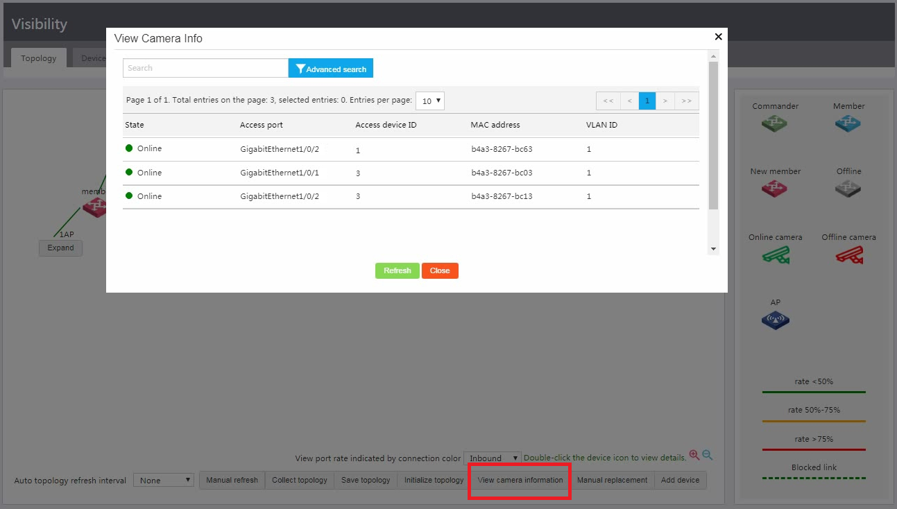
Viewing cameras in the topology
You can access the Visibility > Topology page to view monitored cameras in the topology.
Figure 26 Viewing cameras in the topology
To view detailed information about monitored cameras, click View camera information.
Figure 27 Viewing detailed camera information
Configuring audio and video monitoring
Perform this task to monitor audio and video sessions for multimedia traffic. You can configure SIP-based service quality analysis (SQA) on devices one by one from the CLI or configure SIP-based SQA for multiple devices in bulk from the Web interface.
Configuring SQA
Configuring SQA on a single device from the CLI
You must perform this task on both the commander and members.
To configure SQA on a single device:
1. Enter system view.
system-view
2. Enter SQA view.
sqa
3. Enable SIP-based SQA.
sqa-sip enable
By default, SIP-based SQA is disabled.
4. (Optional.) Specify the SIP listening port number.
sqa-sip port port-number
By default, the SIP listening port number is 5060.
Make sure the SIP listening port number on the device is the same as that on the SIP server.
5. (Optional.) Specify an IP address range for SIP-based SQA.
sqa-sip filter address start-address end-address
By default, no IP address range is specified for SIP-based SQA. The device performs SQA on all SIP packets.
After this command is executed, the device performs SQA only on SIP calls in the specified IP address range.
Configuring SQA on multiple devices from the Web interface
1. Create configuration file Config.cfg and save the file to the file server. The content of the configuration file must contain the following commands:
<FTP Server> more Config.cfg
system-view
sqa
sqa-sip enable
sqa-sip port 5066
sqa-sip filter address 192.168.56.1 192.168.56.244
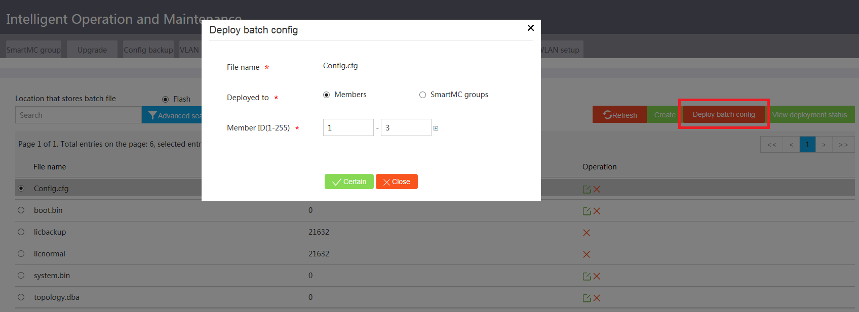
2. Access the Intelligent O&M > Batch deployment page, select the file server as the batch file storage location, and select Config.cfg from the file list.
3. Click Deploy batch config.
4. Select Members as the deployment object, specify the member ID range, and then click Confirm.
Figure 28 Deploying a batch configuration file
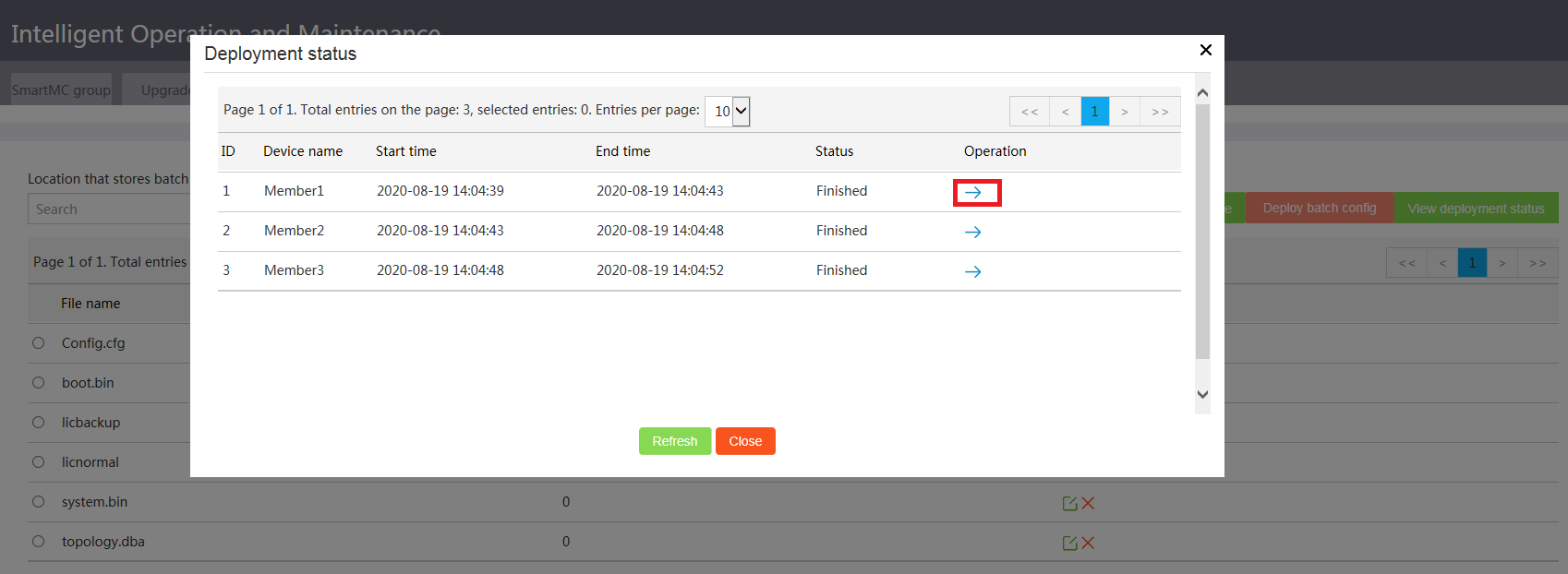
5. Click View deployment status to verify the deployment result.
To view deployment details, click the right chevron icon.
Figure 29 Viewing the deployment status
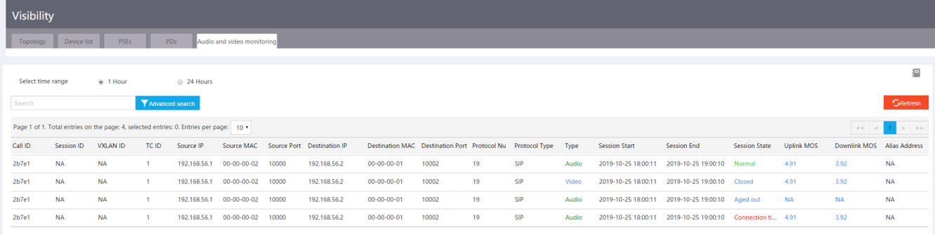
Viewing audio and video monitoring information
You can access the Visibility > Audio and video monitoring page to view detailed information about audio and video monitoring and identify session quality based on the uplink and downlink MOS values.
Figure 30 Viewing audio and video monitoring information
|
|
NOTE: The device whose TC ID is 0 is the commander. A higher MOS value represents a higher session quality. MOS values are in the range of 0 to 5. · 0 to 1—Extremely poor session quality. · 1 to 2—Poor session quality. · 2 to 3—Average session quality. · 3 to 4—Good session quality. · 4 to 5—Excellent session quality. · N/A—The system fails to obtain the MOS value. |
SmartMC feature specifications
|
Item |
Value |
|
Maximum number of supported members |
64 |
|
Maximum number of supported APs |
Same as the number supported by the unified wired and wireless AC on the commander |
|
Maximum number of supported camera monitoring rules |
512 |
|
Maximum number of supported SIP sessions on the commander or a member |
1000 |
SmartMC restrictions and guidelines
As a best practice, use the automatic method to deploy the SmartMC network.
S5130S series switches do not support audio and video monitoring.
To use PoE, make sure the deployed devices are PoE-capable.
A SmartMC network is established in VLAN 1. For the network to work correctly, do not configure security settings in VLAN 1.
Recommended devices for SmartMC
|
Device model |
Commander |
Member |
Recommended version |
|
S6520X-SI |
Supported |
Not supported |
F6509L01 or higher |
|
S6520X-EI |
Supported |
Not supported |
|
|
S6520X-HI |
Supported |
Not supported |
|
|
S5560X-EI |
Supported |
Supported |
|
|
S5560S-EI |
Not supported |
Supported |
R6318 or higher |
|
S5560S-SI |
Not supported |
Supported |
|
|
S5130S-HI |
Not supported |
Supported |
|
|
S5130S-EI |
Not supported |
Supported |
|
|
S5500V3-SI |
Not supported |
Supported |
