| Title | Size | Downloads |
|---|---|---|
| H3C Switches Configuration FAQ-6W102-book.pdf | 951.74 KB |
- Table of Contents
- Related Documents
-
|
|
|
H3C Switches |
|
Configuration FAQ |
|
|
Document version: 6W102-20220815
Copyright © 2022 New H3C Technologies Co., Ltd. All rights reserved.
No part of this manual may be reproduced or transmitted in any form or by any means without prior written consent of New H3C Technologies Co., Ltd.
Except for the trademarks of New H3C Technologies Co., Ltd., any trademarks that may be mentioned in this document are the property of their respective owners.
The information in this document is subject to change without notice.
Contents
Q. How do I recover the password of the console port?
Q. How do I modify the password for Web login?
Q. Can I use a BIDI transceiver module with another type of transceiver module in pair?
Q. Why are the LEDs for an Ethernet port in off state when the Ethernet port operates correctly?
Q. What should I do if the CPU usage is high when not services are running on the device?
Q. How do I deal with an IRF port binding failure?
Q. Do modular switches support the ring topology for an IRF fabric?
Q. Why are some settings lost after an IRF fabric reboots?
Q. What are the requirements for LACP MAD?
Q. What restrictions and guidelines must I follow when I configure the BFD MAD VLAN?
Q. Why cannot the device forward traffic sourced from the MAC address of a VLAN interface?
Interface and link aggregation
Q. Should I manually set the duplex mode and speed on a copper port or fiber port?
Q. What should I do if a combo interface remains in down state?
Q. What restrictions should I follow when I assign ports to an aggregation group?
Q. What are the application scenarios for static and dynamic link aggregation modes?
Q. How to resolve the unbalanced traffic distribution issue occurring on an aggregate link?
Q. How to connect the device to a serve by using an aggregate interface?
Q. Why are packets from some VLANs not permitted to pass through a trunk port?
Q. How can I configure a port to permit the specified VLANs or all VLANs?
Q. Why cannot a device obtain the MAC address of an IP phone?
Q. How can restrict the scope of a broadcast domain?
Q. How can I select a voice VLAN assignment mode of a port?
Q. When should I configure edge ports in a spanning tree network?
Q. Can I configure multiple spanning tree modes in a spanning tree network?
Q. What can I do to maintain the stability of spanning tree network topology?
Q. What should I do if a device receives TC BPDUs frequently?
Q. What factors should I consider when setting the loop detection interval?
Q. Can I configure both loop detection and spanning tree features on a network?
Q. What are the possible reasons for failure to configure source ports for a mirroring group?
Q. Why might configuring a VLAN interface for the remote probe VLAN cause mirroring exceptions?
Q. What will happen if I apply a non-existing DHCP policy to an interface?
Q. What will happen if I specify a narrow network range for dynamic allocation in a DHCP pool?
Q. What should I do if DHCP clients cannot obtain IP addresses after I enable DHCP snooping?
Q. What should I do to have the DHCP server or relay agent settings take effect?
Q. Does DHCP snooping record IP address and MAC address bindings for DHCP clients by default?
Q. What ports should I configure as trusted ports on a DHCP snooping device?
Q. How do I bind a client ID or MAC address to an IP address on a switch acting as a DHCP server?
Q. Why does the DHCP server fail to assign some IP addresses on a DHCP snooping network?
Q. What should I do if I can ping an IP address but I cannot open the webpage at that IP address?
Q. Why am I disconnected every time after I Telnet to the device?
Q. What will happen if IP conflict occurs?
Q. How do I handle the packet loss issue that occurs when the device pings the gateway?
Q. How do I configure an IP address for an Ethernet port on a Layer 2 switch?
Q. What restrictions and guidelines should I follow when I configure a static ARP entry?
Q. In what order does the device select an authentication domain for an access user?
Q. How do I change the default ISP domain to another ISP domain or delete the default ISP domain?
Q. What is local authentication?
Q. How do I enable the 802.1X online user handshake security feature?
Q. What configuration restrictions exist for the 802.1X online user handshake security feature?
Q. In what situations should I enable the 802.1X online user handshake reply feature?
Q. In what situation should I enable port security MAC move?
Q. Why cannot port security MAC move take effect?
Q. How do I configure the default authorization methods?
Q. How do I configure the iNode client when it acts as the 802.1X client?
Q. Before I set a port security mode for a port, what tasks should I complete?
Q. How do I make an endpoint bypass authentication in an 802.1X environment?
Q. In what order does the device select a reauthentication interval for an 802.1X user?
Q. Can I use 802.1X free IPs in conjunction with port security?
Q. In what situation should I enable an authentication trigger?
Q. How do I enable guest VLAN or VSI reauthentication in MAC authentication?
Q. What is IP source guard? From what modules can IP source guard obtain dynamic bindings?
Q. Why cannot IPv4SG take effect after static IPv4SG bindings are configured?
Q. Why cannot portal HTTPS redirect take effect?
Q. What should I do before I configure the 802.1X guest VLAN on a port?
Q. Can I enable unicast trigger on a port if that port performs port-based access control?
Q. How do I configure the user account format for MAC authentication users?
Q. How do 802.1X authentication and MAC authentication relate to port security?
Q. How do I change port security mode?
Q. Can I configure the same network address for a VPN and the public network on a device?
Q. What will happen if PBR configuration errors exist and how do I resolve the issue?
Q. Can I specify an interface that is not up as the output interface for a static route?
Q. Can a device communicate with devices in other networks without a gateway configured for it?
Q. What are the common causes for BGP peer establishment failures and how do I resolve the issue?
Q. How do I view and set the maximum number of ECMP routes supported by the system?
Q. Why do IPv6 routes with a prefix longer than 64 bits not take effect on a device?
Q. Why cannot an IGMP snooping-enabled Layer 2 device process IGMPv3 reports?
Q. Why don't the password control settings take effect?
Q. When the device acts as an SSH server, why can't I log into the device after NTP is configured?
Q. Why can't I change the password of the device?
Q. Why cannot a traffic class containing multiple match criteria match any traffic?
Q. Why cannot an ACL deny incoming packets from a network segment?
Q. Why cannot packets matching an IPSG binding be forwarded?
Q. What is the ACL rule match order?
Q. Why does a VRRP group become invalid after I modify the VRRP version?
Network management and monitoring
Q. What should I do if an NMS fails to monitor and manage a remote device?
Q. Will setting the local clock as a reference clock affect NTP time synchronization accuracy?
Q. Must the clock stratum of the NTP server be smaller than that of the NTP client?
Q. In what conditions can I configure PTP port roles manually? What are the restrictions?
Q. I cannot remotely manage a device from Cloudnet. How do I resolve the issue?
Q. The device generates a large volume of logs. How do I resolve the issue?
Q. I failed to configure VXLAN commands on the device. What should I do?
NOTE
This document provides generic technical information, some of which might not be applicable to your products. For features supported by a product, see the configuration guide for that product.
Login management
This section contains the most frequently asked questions about login management.
Q. How do I resolve the issue that the configuration terminal does not display anything or displays garbled code when the terminal is connected to the console port of the device?
A. To resolve the issue:
1. Verify that the power supply does not have a fault. If a fault exists, fix the fault.
2. Verify that the terminal is correctly connected to the console port.
3. Verify that the console cable does not have damage. If damage exists, replace the console cable with a new one.
4. Verify that the terminal parameters are configured correctly as follows:
¡ Bits per second—9600 bps.
¡ Data bits—8.
¡ Stop bits—1.
¡ Parity—None.
¡ Flow control—None.
5. If the issue persists, replace the console cable with a new one.
6. If the issue still persists, contact H3C Support.
Q. How do I recover the password of the console port?
A. Use one of the following methods to recover the password of the console port:
|
|
IMPORTANT: As a best practice, use method 1 to recover the password of the console port. If you forget all login passwords, use other methods. |
Method 1
To change the password of the console port after you log in to the device through Stelnet or Telnet:
1. Log in to the device through Stelnet or Telnet.
2. Enter system view.
system-view
3. Enter AUX line view or AUX line class view.
¡ Enter AUX line view.
line aux first-number [ last-number ]
¡ Enter AUX line class view.
line class aux
4. Set the login authentication method to password.
authentication-mode password
5. Configure a password for login authentication.
set authentication password { hash | simple } password
6. Assign a user role to the users logging in to the device through the current user line.
user-role role-name
7. Save the running configuration.
save
Method 2
To skip the startup configuration file to start up the device from the BootWare menu and change the password of the console port:
|
|
NOTE: BootWare menu varies by device model. This example uses the BootWare menu of the S5130 switch series. |
1. Connect a configuration terminal to the console port of the device, and reboot the device.
2. During device reboot, press Ctrl+B to enter the BootWare menu. Then, select Skip current system configuration as shown in Figure 1.
Figure 1 Entering the BootWare menu and selecting Skip current system configuration

3. Select Reboot to reboot the device as shown in Figure 2.

4. During the reboot, press Ctrl+C or Ctrl+D to skip automatic configuration as shown in Figure 3.
Figure 3 Skipping automatic configuration

5. Press Enter to skip the startup configuration file to start up the device.
6. View the content of the startup configuration file. The file-name argument specifies the name of the startup configuration file.
more file-name.cfg
7. Select all command lines in the startup configuration file, copy them, and save them to a local file, as shown in Figure 4 and Figure 5.
Figure 4 Copying the content in the startup configuration file
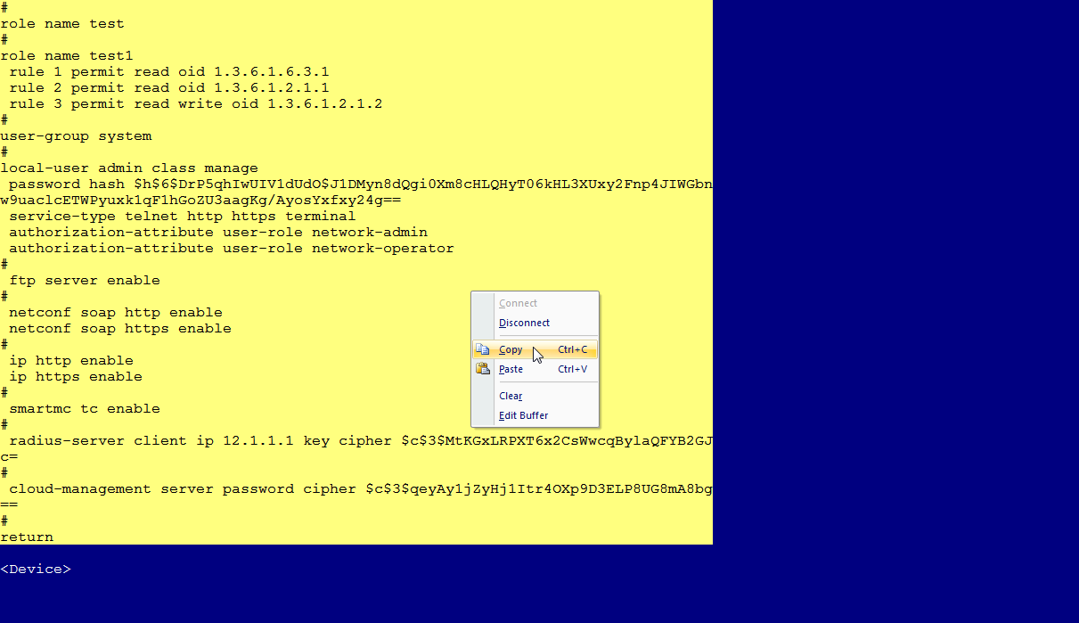
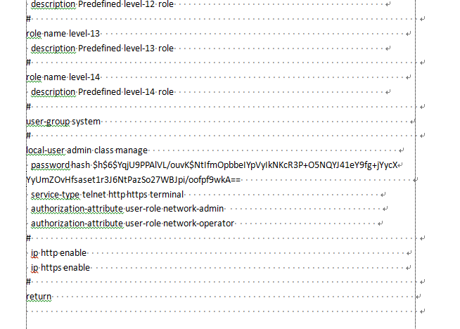
Figure 5 Saving the content of the startup configuration file to a local file
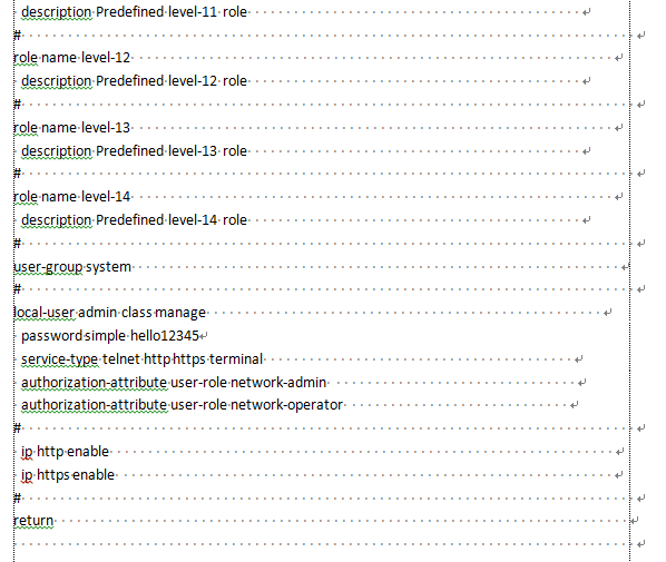
8. Modify the startup configuration file and specify a new password, as shown in Figure 6. In this example, the new password is hello12345.
Figure 6 Configuring a new password
9. Enter system view.
system-view
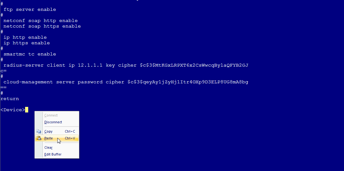
10. Copy the content in the startup configuration file and paste them to the device, as shown in Figure 7.
Figure 7 Pasting the startup configuration file at the CLI
11. Save the configuration.
save
12. Reboot the device.
reboot
Method 3
To skip the startup configuration file to start up the device from the BootWare menu and roll back the running configuration:
1. Skip the startup configuration file to start up the device as described in method 2.
2. Enter system view.
system-view
3. Roll back the running configuration to the configuration in a configuration file, for example, startup.cfg.
configuration replace file file-name.cfg
4. Enter N to not save the running configuration.
5. After the configuration rollback completes, enter system view.
system-view
6. Enter AUX line view or AUX line class view.
¡ Enter AUX line view.
line aux first-number [ last-number ]
¡ Enter AUX line class view.
line class aux
7. Set the login authentication method to password.
authentication-mode password
8. Configure a password for authentication.
set authentication password { hash | simple } password
9. Assign a user role to the users logging in to the device through the current user line.
user-role role-name
10. Save the running configuration.
save
Method 4
To skip the startup configuration file to start up the device from the BootWare menu and restore the device configuration to the factory defaults:
|
|
CAUTION: The operations in this method clear all settings from the device. Make sure you fully understand the impacts of the operations on services. |
1. Skip the startup configuration file to start up the device as described in method 2.
2. Save the running configuration. In this method, the running configuration is the factory defaults.
save
3. Reboot the device.
Reboot
Q. How do I modify the password for Web login?
A. To resolve the issue:
1. Log in to the device through the console port, Stelnet, or Telnet.
2. Enter system view.
system-view
3. Enter the view of the Web login local user.
local-user user-name
4. Configure a new password for Web login.
password [ { hash | simple } password ]
User permissions
This section contains the most frequently asked questions about user permissions.
Q. What should I do if I am denied access to commands, features, or resources because of insufficient privileges?
A. You can execute a command, configure a feature, or operate on a resource only if that command, feature, or resource is accessible to one of the user roles with which you logged in. To execute the command, configure the feature, or operate on the resource, use a user that has the network-admin user role.
Device management
Q. What should I do if the SYS LED of a device that uses removable fan trays is steady red after the device boots up?
|
|
NOTE: The LEDs vary by device model. For more information, see the installation guide for the device. This example uses the LEDs on the S5560X-EI switch series. |
A. Perform the following steps:
1. Verify whether the airflow direction of the fan trays is consistent with the preferred airflow direction configured on the device. If they are inconsistent, the SYS LED is steady red.
A fan tray provides port-side intake and power supply-side exhaust airflow or power supply-side intake or port-side exhaust airflow depending on the fan tray model. To identify the airflow direction of a fan tray, see the fan tray manual, or execute the display fan command to view the value of the Airflow Direction field.
To identify the preferred airflow direction of a device, execute the display fan command and view the value of the Airflow Direction field.
<Sysname> display fan
Slot 1:
Fan 1:
State : Normal
Airflow Direction: Port-to-power
Prefer Airflow Direction: Port-to-power
2. If they are inconsistent, execute the fan prefer-direction command in system view to configure the preferred airflow direction to be consistent with that of the fan trays.
¡ To configure the preferred airflow direction to be from port side to the power supply side, specify the port-to-power keyword.
¡ To configure the preferred airflow direction to be from power supply side to the port side, specify the power-to-port keyword.
Whether the system checks the consistency between the airflow direction of the fan trays and the preferred airflow direction depends on the device model and software release. For more information, see the installation guide for the device.
Q. What kind of faults will occur if fan trays are not installed correctly? How do I ensure correct installation of fan trays?
A. If fan trays are not installed correctly, the following issues might occur:
· The device cannot start after power on.
· The device runs with low load but loud fan tray noises.
· The device shuts down automatically.
· The device temperature is over high.
· Error logs are generated.
To ensure correct installation of fan trays, verify the following items:
· The fan trays are installed securely.
· The installed fan trays models are compatible with the device.
· A sufficient number of fan trays are installed.
· The installed fan trays have the same airflow direction.
· The airflow direction of the fan trays is consistent with the configured airflow direction.
Q. Can I use a BIDI transceiver module with another type of transceiver module in pair?
A. No. A BIDI transceiver module can be used only with another matched BIDI transceiver module in pair. For example, if one end uses an SFP-XG-LX-SM1270-BIDI transceiver module, the peer end must use an SFP-XG-LX-SM1330-BIDI transceiver module. For the BIDI transceiver modules available for the device and the matched BIDI transceiver module models, see the installation guide for the device.
Q. Why are the LEDs for an Ethernet port in off state when the Ethernet port operates correctly?
A. If the LEDs are in good condition and a MODE button is available for LED mode switching, the reason for this issue varies depending on the device model.
· On a PoE device:
¡ If the MODE LED is flashing green, the ports on the device operate in PoE mode. If you do not enable PoE for a port, the status LED of the port is off.
¡ If the MODE LED is flashing yellow, the ports on the device operate in IRF mode. In this mode, the port LEDs are turned on or off to indicate the IRF member ID of the device. The mechanism varies depending on the device mode.
· On a non-PoE device:
¡ If the MODE LED is flashing yellow, the ports on the device operate in IRF mode. In this mode, the port LEDs are turned on or off to indicate the IRF member ID of the device. The mechanism varies depending on the device mode.
If the member ID of an IRF member device is n, its port LEDs are set as follows:
· S5560X-EI, S6520X-EI, S6520X-HI switch series—All port LEDs are off except that the one with the same sequence number as the IRF member ID is steady green.
· S5130S-EI, S5130S-HI, S5560S-EI switch series—All port LEDs are off except that the LEDs whose sequence numbers are in the range of 1 to n are steady green.
For more information about the LED mode switching button, see LED introduction in the installation guide for your device.
Q. What are the possible reasons for a prompt indicating resource insufficiency when a new ACL is added?
A. The following are possible reasons:
· The ACL resources on the device have reached the upper limit. In this case, perform the following steps:
a. Execute the display qos-acl resource command to verify that no ACL resources are available.
b. To add a new ACL, first delete useless AC rules, QoS policies, and PBR policies. Make sure the free memory is sufficient for adding ACLs.
· The device has reached the default memory threshold. In this case, execute the display memory command to identify the memory usage, and then release the memory space as needed to provide sufficient memory for adding ACLs.
· The memory alarm thresholds are mistakenly set too low, which causes the device to abnormally determine that the memory usage has reached the upper limit. In this case, execute the display memory-threshold command to obtain memory alarm thresholds and statistics, and then execute the undo memory-threshold command to restore free-memory thresholds. Make sure the free memory space does not reach any threshold. For more information about configuring free-memory thresholds, see the fundamentals configuration guide for the device.
If the issue persists, contact H3C Support.
Q. What should I do if the CPU usage is high when not services are running on the device?
A. To resolve the issue:
1. Execute the display process cpu command to obtain CPU usage information for all processes.
2. If the CPU usage for the TMTH thread is too high, identify whether an interface is inserted with a transceiver module or network cable but no peer is connected. If yes, the device will always attempt to bring up the interface, which causes the TMTH thread as the interface training process to occupy CPU resources. In this case, shut down the interface manually, and then execute the display cpu-usage command to obtain CPU usage information to make sure CPU usage information becomes normal.
3. If the issue persists, contact H3C Support.
IRF
This section contains the most frequently asked questions about IRF.
Q. What should I do if the system prompts me to shut down a physical interface first when I bind it to an IRF port?
A. Shut down the physical interface as instructed.
The message generated in this situation varies by device model. The following shows a sample output:
<Sysname> system-view
[Sysname-irf-port1/1] port group interface ten-gigabitethernet 1/0/1
Please shutdown the current interface first.
To bind an interface (for example, Ten-GigabitEthernet 1/0/1) to an IRF port (for example, IRF-port 1/1):
1. Enter the view of Ten-GigabitEthernet 1/0/1 and shut down the physical interface.
<Sysname> system-view
[Sysname] interface ten-gigabitethernet 1/0/1
[Sysname-Ten-GigabitEthernet1/0/1] shutdown
[Sysname] quit
2. Enter the view of IRF-port 1/1 and bind Ten-GigabitEthernet 1/0/1 to IRF-port 1/1.
[Sysname] irf-port 1/1
[Sysname-irf-port1/1] port group interface ten-gigabitethernet 1/0/1
You must perform the following tasks for a successful IRF setup:
Save the configuration after completing IRF configuration.
Execute the "irf-port-configuration active" command to activate the IRF ports.
[Sysname-irf-port1/1] quit
3. Enter the view of Ten-GigabitEthernet 1/0/1 again and bring up the physical interface.
[Sysname] interface ten-gigabitethernet 1/0/1
[Sysname-Ten-GigabitEthernet1/0/1] undo shutdown
[Sysname-Ten-GigabitEthernet1/0/1] quit
4. Repeat the previous steps to bind other IRF physical interfaces to the IRF port. (Details not shown.)
5. Save the configuration.
[Sysname] save
The current configuration will be written to the device. Are you sure? [Y/N]:y
Please input the file name(*.cfg)[flash:/startup.cfg]
(To leave the existing filename unchanged, press the enter key):
Validating file. Please wait...
The startup.cfg file already exists.
Compared with the startup.cfg file, The current configuration adds 5 commands and d
eletes 1 commands.
If you want to see the configuration differences, please cancel this operation,
and then use the display diff command to show the details.
If you continue the save operation, the file will be overwritten.
Are you sure you want to continue the save operation? [Y/N]:y
Saving the current configuration to the file. Please wait...
Saved the current configuration to mainboard device successfully.
6. Activate IRF port configuration.
[Sysname] irf-port-configuration active
This example contains only the IRF physical interface binding procedure. For information about the complete IRF configuration procedure, see IRF configuration in Virtual Technologies Configuration Guide.
Q. How do I deal with an IRF port binding failure?
A. To resolve the issue:
1. Verify that the IRF physical interfaces can be bound to an IRF port. If a physical interface cannot be used as an IRF physical interface, replace it with a physical interface that can be used as an IRF physical interface. For information about candidate IRF physical interfaces, see IRF configuration in Virtual Technologies Configuration Guide.
2. Verify that all IRF physical interfaces (including breakout interfaces) are operating at their highest rate if they are required to operate at their highest rate. If they are not operating at their highest rate, replace their peer ports or connection media to make sure they are operating at their highest rate.
3. Verify that the IRF port bindings meet the port grouping restrictions if the device has port grouping restrictions for IRF port bindings.
If ports are grouped, only ports in the same group can be bound to the same IRF port on some device models. For more information about IRF physical interface configuration requirements and port grouping restrictions, see IRF configuration in Virtual Technologies Configuration Guide or the installation guide for the device.
4. If the issue persists, contact H3C Support.
Q. What should I do if the system prompts me to shut down all ports in a port group when I bind one of them to an IRF port as an IRF physical interface?
A. Shut down all ports in that port group as instructed.
If ports are grouped, you must use all ports in the same group as IRF physical interfaces or use none of the ports as IRF physical interfaces on some device models. If any of the ports are up, you cannot bind any of the ports in the group as IRF physical interfaces. To bind a port in the group to an IRF port, you must first shut down all ports in the group. For more information about port groups, see the command output for the IRF port binding operation or IRF configuration in Virtual Technologies Configuration Guide.
The message generated in this situation varies by device model. The following shows a sample output:
<Sysname> system-view
[Sysname]irf-port 1/2
[Sysname-irf-port1/2]port group interface Twenty-FiveGigE 1/0/13:1
Check failed for reason:
Twenty-FiveGigE1/0/13:2, Twenty-FiveGigE1/0/13:3 and Twenty-FiveGigE1/0/13:4 belong to a port group, Please shutdown all of them before changing the working mode.
When you receive the message that requires you to shut down all ports in a port group, use the following procedure to bind the IRF physical interfaces in the port group to IRF ports:
1. Enter the port range view for all ports in the target port group, and then shut down the ports. This example uses the port group of Twenty-FiveGigE 1/0/13:1, Twenty-FiveGigE 1/0/13:2, Twenty-FiveGigE 1/0/13:3, and Twenty-FiveGigE 1/0/13:4 for example.
[Sysname] interface range twenty-fivegige 1/0/13:1 twenty-fivegige 1/0/13:2 twenty-fivegige 1/0/13:3 twenty-fivegige 1/0/13:4
[Sysname-if-range] shutdown
[Sysname-if-range] quit
2. Enter the view of the target IRF port (for example, IRF-port 1/2) and bind Twenty-FiveGigE 1/0/13:1 to the IRF port.
[Sysname] irf-port 1/2
[Sysname-irf-port1/2] port group interface twenty-fivegige 1/0/13:1
You must perform the following tasks for a successful IRF setup:
Save the configuration after completing IRF configuration.
Execute the "irf-port-configuration active" command to activate the IRF ports.
[Sysname-irf-port1/2] quit
3. Enter the view of Twenty-FiveGigE 1/0/13:1 and bring up the port. Do not bring up the other ports that have not been bound to IRF ports.
[Sysname] interface twenty-fivegige 1/0/13:1
[Sysname-Twenty-FiveGigE1/0/13:1] undo shutdown
[Sysname-Twenty-FiveGigE1/0/13:1] quit
4. Repeat the previous two steps to bind the other ports in the port group to IRF ports. (Details not shown.)
5. Save the configuration.
[Sysname] save
The current configuration will be written to the device. Are you sure? [Y/N]:y
Please input the file name(*.cfg)[flash:/startup.cfg]
(To leave the existing filename unchanged, press the enter key):
Validating file. Please wait...
The startup.cfg file already exists.
Compared with the startup.cfg file, The current configuration adds 5 commands and d
eletes 1 commands.
If you want to see the configuration differences, please cancel this operation,
and then use the display diff command to show the details.
If you continue the save operation, the file will be overwritten.
Are you sure you want to continue the save operation? [Y/N]:y
Saving the current configuration to the file. Please wait...
Saved the current configuration to mainboard device successfully.
6. Activate the IRF port configuration.
[Sysname] irf-port-configuration active
7. If the issue persists, contact H3C Support.
This example contains only the IRF physical interface binding procedure. For information about the complete IRF configuration procedure, see IRF configuration in Virtual Technologies Configuration Guide.
Q. When I bring up a port after I bind it to an IRF port, the system prompts me to bind all ports in the same group as this port to IRF ports or cancel the bindings on all of them. How do I resolve this issue?
A. Bind all ports in the same group as this port to IRF ports or cancel the bindings on all of them as instructed.
The message generated in this situation varies by device model. The following shows a sample output:
<Sysname> system-view
[Sysname] interface Twenty-FiveGigE 1/0/13:2
[Sysname-Twenty-FiveGigE1/0/13:2] undo shutdown
Bind all interfaces in the same group to IRF ports or cancel the bindings on all of them.
To resolve this issue:
1. Bind all ports in the port group to IRF ports or cancel the bindings on all of them. To display IRF physical interfaces that have been bound to an IRF port, execute the display this command on the IRF port. To obtain port grouping information, see IRF configuration in Virtual Technologies Configuration Guide.
2. If the issue persists, contact H3C Support.
Q. What should I do if the IRF candidate devices fail to form an IRF fabric on reboot after I have configured them with IRF member IDs and physical interface and IRF port bindings?
A. Make sure you have saved the configuration.
On fixed-port devices, make sure you have performed the following steps in strict order:
1. Complete the settings required for IRF setup, including binding physical interfaces to IRF ports.
2. Execute the save command to save the configuration.
3. Execute the irf-port-configuration active command to activate IRF port settings.
4. Connect IRF physical interfaces on member devices.
On modular devices, make sure you have performed the following steps in strict order:
1. Complete the settings required for IRF setup, including binding physical interfaces to IRF ports.
2. Execute the save command to save the configuration.
3. Connect IRF physical interfaces on member devices.
4. Convert the operating mode to IRF mode.
Forgetting to save the configuration is the most common reason causing IRF setup failure. For more information about the reasons that can cause IRF setup failure, see the troubleshoot guide for the device.
Q. How do I deal with the IRF setup failure caused by inconsistent settings on member devices after I execute the irf-port-configuration active command to activate the IRF port configuration?
A. Remove the inconsistencies and try again.
The settings that must be consistent across IRF member devices vary by device model. The following are the most common settings that must be consistent across IRF member devices:
· System working mode (set by using the system-working-mode command).
· Hardware resource operating mode (set by using the hardware-resource switch-mode command or the switch-mode command).
· Link aggregation capability for the device (configured by using the link-aggregation capability command).
· ECMP mode (set by using the ecmp mode command).
· Maximum number of ECMP routes (set by using the max-ecmp-num command).
· Support for IPv6 routes with prefixes longer than 64 bits (set by using the hardware-resource routing-mode ipv6-128 command).
· VXLAN hardware resource mode (set by using the hardware-resource vxlan command).
For more information about the requirements for configuration consistency, see IRF configuration in Virtual Technologies Configuration Guide.
The following shows a sample output that contains a configuration inconsistency message:
[Sysname]irf-port-configuration a
[Sysname]irf-port-configuration active
[Sysname]%Jan 14 20:53:07:484 2013 H3C STM/6/STM_LINK_UP: IRF port 2 came up.
The max-ecmp-num and switch-mode settings should be the same across devices in an IRF fabric. The local max-ecmp-num setting is 8, and the local switch-mode setting is VXLAN. Please check the settings on the neighbor device connected to IRF-port 2.
%Jan 14 20:53:07:864 2013 H3C STM/3/STM_SOMER_CHECK: Neighbor of IRF port 2 can't be stacked.
%Jan 14 20:53:08:088 2013 H3C STM/3/STM_LINK_DOWN: IRF port 2 went down.
To resolve the configuration inconsistency issue, change the settings on the local device or on the neighboring device.
The following information uses this sample output to describe how to remove a configuration inconsistency issue.
1. Read the configuration inconsistency message on the local device.
The message shows that the max-ecmp-num and switch-mode settings must be consistent across member devices in the IRF fabric. However, the settings are inconsistent between the local device and the neighboring device connected to IRF-port 2. The local max-ecmp-num setting is 8, and the local switch-mode setting is VXLAN.
2. Examine the max-ecmp-num and switch-mode settings on the neighboring device connected to IRF-port 2.
[Sysname] display switch-mode status
Switch-mode in use: NORMAL MODE(default).
Switch-mode for next reboot: NORMAL MODE(default).
[Sysname] display max-ecmp-num
Max-ECMP-Num in use: 8
Max-ECMP-Num at the next reboot: 8
The output shows that the max-ecmp-num setting is 8 and the switch-mode setting is NORMAL on the neighboring device connected to IRF-port 2. The switch-mode setting is inconsistent between the local and neighboring devices.
3. Change the switch-mode setting on the local device or neighboring device. If the IRF fabric contains other member devices, make sure all the member devices (including the local device and its neighboring device) have the same max-ecmp-num and switch-mode settings.
After you change the settings, save the configuration and reboot the member devices to have the settings take effect.
[Sysname] switch-mode ?
0 NORMAL MODE(default)
1 VXLAN MODE
2 802.1BR MODE
3 MPLS MODE
4 MPLS-IRF MODE
[Sysname] switch-mode 0
Reboot device to make the configuration take effect.
[Sysname]
<Sysname> reboot
Start to check configuration with next startup configuration file, please wait..
.......DONE!
Current configuration may be lost after the reboot, save current configuration?
[Y/N]:y
Please input the file name(*.cfg)[flash:/test.cfg]
(To leave the existing filename unchanged, press the enter key):
flash:/test.cfg exists, overwrite? [Y/N]:y
Validating file. Please wait...
Saved the current configuration to mainboard device successfully.
This command will reboot the device. Continue? [Y/N]:y
Now rebooting, please wait........
Q. Do modular switches support the ring topology for an IRF fabric?
A. For models that support only two member devices in an IRF fabric, the ring topology is not supported.
For models that support a maximum of four member devices in an IRF fabric, the ring topology is supported only when the IRF fabric contains three or four member devices.
For information about the maximum number of member devices in an IRF fabric and the supported network topologies, see IRF configuration in Virtual Technologies Configuration Guide for the device.
Q. Why are some settings lost after an IRF fabric reboots?
A. The loss might be caused by the following reasons:
· The changed settings are not saved before the IRF fabric reboots.
· A subordinate device is rebooting while the IRF fabric is saving the running configuration to the startup configuration file. The settings saved in the startup configuration file do not contain settings on the subordinate device. When the subordinate device starts up and rejoins the IRF fabric, it cannot restore settings from the startup configuration file. As a result, the settings on the subordinate device are lost.
· Settings for some features are not supported on the IRF fabric after software upgrade. These settings are lost.
· If a modular switch has not been powered on for a long time, the NVRAM on the active MPU might not have sufficient power. As a result, the path information for the startup configuration file gets lost on the NVRAM. When you power on the device, the device starts up with the initial settings. Settings not in the initial settings are lost. In this situation, check the system time after the device starts up. If the system time is not accurate according to the configuration you have made, the NVRAM on the active MPU does not have sufficient power. To resolve the issue, please contact H3C Support to replace the battery on the MPU.
Q. What are the requirements for LACP MAD?
A. To use LACP MAD, an IRF fabric must have a dynamic link aggregation with an upstream or downstream device that supports extended LACP for MAD, preferably, an H3C device. This upstream or downstream device is called an intermediate device.
For LACP MAD to operate correctly, you must configure the link aggregation between the IRF fabric and the intermediate device as follows:
· Make sure each IRF member device has a minimum of one link to the intermediate device.
· Assign all the links to the link aggregation group for an aggregate interface.
· Set the aggregation mode of the aggregate interface to dynamic.
Q. What restrictions and guidelines must I follow when I configure the BFD MAD VLAN?
A. To have BFD MAD operate correctly, follow these restrictions and guidelines:
· Do not enable BFD MAD on VLAN-interface 1.
· If you are using an intermediate device, perform the following tasks:
¡ On the IRF fabric and the intermediate device, create a VLAN for BFD MAD.
¡ On the IRF fabric and the intermediate device, assign the ports of BFD MAD links to the BFD MAD VLAN.
¡ On the IRF fabric, create the VLAN interface for the BFD MAD VLAN.
· Make sure the IRF fabrics on the network use different BFD MAD VLANs.
· Make sure the BFD MAD VLAN contains only ports at the two ends of the BFD MAD links. Exclude a port from the BFD MAD VLAN if that port is not on a BFD MAD link. If you have assigned that port to all VLANs by using the port trunk permit vlan all command, use the undo port trunk permit command to exclude that port from the BFD MAD VLAN.
· If you need to create VSI interfaces on the following devices, avoid enabling BFD MAD on VLAN interfaces that are not configurable for BFD MAD when VSI interfaces are present:
|
Switch series |
VLAN interfaces not configurable for BFD MAD when VSI interfaces are present |
|
S5560X-EI series S5500V2-EI series ES5500C series MS4520V2 series |
3581 to 4092 |
|
S6520X-SI series S6520-SI series MS4600 series |
3581 to 4092 |
|
S6520X-EI series |
3069 to 4092 |
|
S6520X-HI series S5560X-HI series S5000-EI series |
2045 to 4092 |
|
S6813 & S6812 series |
2045 to 4092 |
· Do not configure the BFD MAD VLAN interface and its member ports for any purposes other than BFD MAD.
¡ Use only the mad bfd enable and mad ip address commands on the BFD MAD VLAN interface. If you configure the interface to provide other services, both BFD MAD and other services might operate incorrectly.
¡ Disable the spanning tree feature on all Layer 2 Ethernet ports in the BFD MAD VLAN. The MAD feature is mutually exclusive with the spanning tree feature.
MAC address table
This section contains the most frequently asked questions about the MAC address table.
Q. Why cannot the device forward traffic sourced from the MAC address of a VLAN interface?
A. When the static source check feature is enabled on an interface, the check identifies whether a received frame meets the following conditions:
· The source MAC address of the frame matches a static MAC address entry.
· The incoming interface of the frame is different from the outgoing interface in the entry.
If the frame meets both conditions, the device drops the frame.
To correctly forward traffic sourced from the MAC address of a VLAN interface, you must disable the static source check feature on the Layer 2 interfaces in the VLAN.
To disable the static source check feature on the Layer 2 interfaces in the VLAN:
1. Enter system view.
system-view
2. Enter Layer 2 Ethernet interface view.
interface interface-type interface-number
3. Disable the static source check feature on the interface.
undo mac-address static source-check enable
By default, the static source check feature is enabled on an interface.
This issue does not occur on devices that do not support the undo mac-address static source-check enable command, such as the S12500X-AF, S12500F-AF ,and S6890 switches.
Interface and link aggregation
Q. Should I manually set the duplex mode and speed on a copper port or fiber port?
A. Typically, a copper port can successfully negotiate the duplex mode and speed with the peer. You do not need to manually set the duplex mode or speed on a copper port.
A fiber port might fail to negotiate the duplex mode and speed with the peer. Typically, the duplex mode and speed are manually configured on a fiber port. When a fiber port operates incorrectly, you need to check the error packet statistics, light degrade, and optical power for the cause and replace the optical fiber as needed.
When you configure the duplex mode and speed on a copper port or fiber port, follow these guidelines:
· Check the device installation guides for duplex mode and speed requirements. Unless fixed duplex mode and speed are required, use automatic duplex node and speed negotiation.
· You must configure the same duplex mode and speed settings for the two ends of a link. If you use manual configuration, you must set both the duplex mode and speed.
Q. What should I do if a combo interface remains in down state?
A. A combo interface is a logical interface that physically comprises one fiber combo port and one copper combo port. The two ports share one forwarding channel and one interface view. As a result, they cannot work simultaneously. When you activate one port, the other port is automatically disabled.
The device provides two combo interfaces. Each combo interface comprises one 10/100/1000BASE-T autosensing Ethernet port and one SFP port on the front panel, as shown in Figure 8.
Figure 8 Physical ports used by combo interfaces
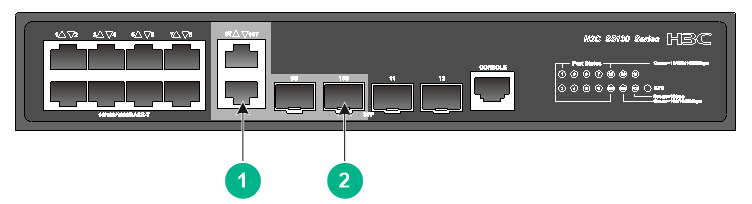
|
(1) 10/100/1000BASE-T autosensing Ethernet port |
(2) SFP port |
To bring up a combo interface, use the following workflow:
1. Check whether the copper port of a combo interface is active by using the display interface command. The copper port is active is the command output contains Media type is twisted pair.
2. Activate the copper port or fiber port of a combo interface by using the combo enable { copper | fiber } command.
Q. What restrictions should I follow when I assign ports to an aggregation group?
A. Follow these restrictions when you assign a port to an aggregation group:
· On some device models, the port must have the same attribute configuration as that of the aggregate interface to join the aggregation group.
· On other device models, the port with different attribute configuration from that of the aggregate interface can join an aggregation group, but the port will become unselected.
Follow these restrictions when you edit a member port in an aggregation group:
· On some device models, you cannot modify the attribute configuration for a port that is already in an aggregation group.
· On other device models, an aggregation member port will become unselected if you modify its attribute configuration.
Unselected aggregation member ports cannot forward traffic. For more information about aggregation states of aggregation member ports, see Layer 2—LAN Switching Configuration Guide.
Table 1 shows the attribute configuration.
Table 1 Attribute configuration
|
Feature |
Attribute configuration |
|
Port isolation |
Membership of the port in an isolation group. Isolation group number. |
|
QinQ |
QinQ status (enabled/disabled), TPID for VLAN tags, and VLAN transparent transmission. |
|
VLAN mapping |
VLAN mapping configured on the port. |
|
VLAN |
VLAN attribute settings: · Permitted VLAN IDs. · PVID. · Link type (trunk, hybrid, or access). · PVLAN port type (promiscuous, trunk promiscuous, host, or trunk secondary). · IP subnet-based VLAN configuration. · Protocol-based VLAN configuration. · VLAN tagging mode. |
Do not assign a reflector port for port mirroring to an aggregation group.
A Layer 2 extended-link aggregation group can contain only extended ports that are on the same PEX or on the same-tier PEXs in the same PEX group. In the latter case, the PEXs must belong to the same series.
Q. What are the application scenarios for static and dynamic link aggregation modes?
A. The aggregation states of the member ports in a static aggregation group are not affected by the peer ports. Use static link aggregation mode if the network is stable.
Dynamic aggregation is implemented through IEEE 802.3ad Link Aggregation Control Protocol (LACP). The local system and the peer system automatically maintain the aggregation states of the member ports. Use dynamic link aggregation to reduce the administrators' workload.
For a successful static aggregation, make sure the ports at both ends of each link are in the same aggregation state.
For a successful dynamic aggregation:
· Make sure the ports at both ends of a link are assigned to the correct aggregation group. The two ends can automatically negotiate the aggregation state of each member port.
· If you use automatic interface assignment on one end, you must use manual assignment on the other end.
Q. How to resolve the unbalanced traffic distribution issue occurring on an aggregate link?
A. To resolve the unbalanced traffic distribution issue, perform the following tasks:
· Adjust the load sharing mode.
Use the link-aggregation global load-sharing mode command in system view and the link-aggregation load-sharing mode command in aggregate interface view to adjust the load sharing modes.
You can configure the device to load share Layer 3 traffic based on the source or destination IP address and load share Layer 2 traffic based on the source or destination MAC address.
· Disable local-first load sharing for link aggregation.
Use the undo link-aggregation load-sharing mode local-first command to disable local-first load sharing if multichassis aggregate links exist on an IRF fabric. The IRF fabric might be unstable if the traffic on the multichassis aggregate links is large.
Q. How to connect the device to a serve by using an aggregate interface?
A. To connect an aggregate interface to a server, you must use the lacp edge-port command to configure the aggregate interface as an edge aggregate interface. In addition, configure the aggregate interface to operate in dynamic mode.
The edge aggregate interface feature enables all member ports of an aggregation group to forward traffic. When a member port fails, its traffic is automatically switched to other member ports.
DRNI
This section contains the most frequently asked questions about DRNI.
Q. What should I do if the DR member devices in a DR system cannot communicate with each other by using their management IP addresses?
To resolve this issue:
· Execute the undo mac-address static source-check enable command in system view or IPP view.
· Assign the DR interfaces only to the VLANs that transmit service traffic.
· Connect both DR member devices to the upstream device.
Q. What should I do if the primary DR member device receives identical ICMP packets in a DR system with VRRP configured and singlehomed devices attached?
To resolve this issue, assign any DR interface to the VLAN of the VLAN interface where a VRRP group is configured.
VLAN
This section contains the most frequently asked questions about VLANs.
Q. Why are packets from some VLANs not permitted to pass through a trunk port?
A possible reason is that the trunk port is not assigned to these VLANs. Additionally, for packets to be correctly forwarded, make sure the PVID is the same on both the local trunk port and remote trunk port. To resolve this issue, first execute the display vlan command to identify whether the port are assigned to these VLANs. If not, execute the port trunk permit vlan command in interface view to assign the port to these VLANs, and execute the port trunk pvid command to configure the correct PVID for the port.
Q. How can I configure a port to permit the specified VLANs or all VLANs?
To configure a port to permit the specified VLANs or all VLANs:
1. Enter system view.
system-view
2. Enter interface view.
¡ Enter Layer 2 Ethernet interface view.
interface interface-type interface-number
¡ Enter Layer 2 aggregate interface view.
interface bridge-aggregation interface-number
3. Configure the link type of the port as trunk.
port link-type trunk
By default, the link type of a port is access.
4. Assign the port to the specified VLANs or all VLANs.
port trunk permit vlan { vlan-id-list | all }
By default, a trunk port is assigned only to VLAN 1.
5. Configure the PVID of the port.
port trunk pvid vlan vlan-id
By default, the PVID of a trunk port is VLAN 1.
As a best practice to prevent users in unauthorized VLANs from access restricted resources through this port, use the port trunk permit vlan all command with caution.
Q. Why cannot a device obtain the MAC address of an IP phone?
A possible reason is that the MAC address of the IP phone is not within the default OUI addresses of the device. To resolve this issue, first configure the OUI address of the IP phone on the device, and then execute the display voice-vlan mac-address command to verify that the OUI address of the IP phone exists in the command output.
To configure the OUI address of the IP phone on the device:
1. Enter system view.
system-view
2. Configure the OUI address information for voice packet identification.
voice-vlan mac-address oui mask oui-mask [ description text ]
After the voice VLAN feature is enabled, the default OUI addresses exist in the system. For more information about OUI address configuration, see VLAN configuration in Layer 2—Ethernet Switching Configuration Guide for your product.
When you configure the OUI address information for voice packet identification, follow these restrictions and guidelines:
· An OUI address cannot be a broadcast address, multicast address, or all-zero address.
· The OUI addresses are the results of the AND operation between the mac-address and oui-mask parameters.
· The maximum number of OUI addresses supported varies by device model.
Q. How can restrict the scope of a broadcast domain?
You can configure a VLAN to restrict broadcast packets within the VLAN, which effectively restricts the scope of a broadcast domain. The switch supports the following types of VLANs: port-based, MAC-based, IP subnet-based, and protocol-based. Support for VLAN type varies by device model. For more information, see VLAN configuration in Layer 2—Ethernet Switching Configuration Guide for your some product.
Q. Communication fails because the link type of a port is incorrectly configured. How can I resolve this issue?
First, understand the purposes of the three link types.
· Access—An access port can forward packets only from one VLAN and send these packets untagged. An access port is typically used in the following conditions:
¡ Connecting to a terminal device that does not support VLAN packets.
¡ In scenarios that do not distinguish VLANs.
· Trunk—A trunk port can forward packets from multiple VLANs. Except packets from the port VLAN ID (PVID), packets sent out of a trunk port are VLAN-tagged. Ports connecting network devices are typically configured as trunk ports.
· Hybrid—A hybrid port can forward packets from multiple VLANs. The tagging status of the packets forwarded by a hybrid port depends on the port configuration.
Then, use the port link-type command to configure a correct link type for the port according to whether the port needs to forward packets with VLAN tags and forward packets from multiple VLANs.
To change the link type of a port from trunk to hybrid or vice versa, first set the link type to access.
Q. Data packets from a voice VLAN are dropped but voice packets can be forwarded correctly. How can I resolve this issue?
To resolve this issue, use the undo voice-vlan security enable command to disable the voice VLAN security mode. In security mode, a port uses the source MAC addresses of packets to match the OUI addresses of the device. Packets that fail the match will be dropped. As a best practice, do not transmit both voice packets and data packets in a voice VLAN. If you must transmit both data packets and voice packets in a voice VLAN, make sure the voice VLAN security mode is disabled.
Q. How can I select a voice VLAN assignment mode of a port?
Depending on how a port is assigned to a voice VLAN, you can configure the voice VLAN assignment mode as automatic or manual. Select a mode as follows:
· Automatic mode—The automatic mode is applicable when the host and IP phone are connected to the device in series, as shown in Figure 9. In this case, the connecting port transmits both voice traffic and data traffic.
Figure 9 Connecting a host and IP phone in series to the device

· Manual mode—The manual mode is applicable when the IP phone is connected to the device separately, as shown in Figure 10. In this case, the access port transmits only voice traffic. In this network mode, you can configure the access port to transmit only voice traffic, and avoid the impact of data traffic on voice traffic transmission. This network mode applies when the IP phone sends untagged voice packets. Table 2 describes the configuration requirements for ports of different link types to send untagged voice packets.
Figure 10 Connecting an IP phone to the device separately
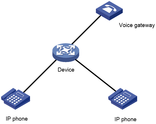
Table 2 Configuration requirements for ports of different link types to send untagged packets
|
Voice VLAN assignment mode |
Port link type |
Untagged voice packet support |
Configuration requirements |
|
Manual mode |
Access |
Supported |
Assign the port to the voice VLAN |
|
Trunk |
Supported |
Configure the PVID as the voice VLAN, and assign the port to the PVID |
|
|
Hybrid |
Supported |
Configure the PVID as the voice VLAN, and assign the port to the PVID as an untagged member |
Spanning tree protocol
This section contains the most frequently asked questions about spanning tree protocol (STP).
Q. When should I configure edge ports in a spanning tree network?
A. Do not configure spanning tree protocols on customer-side devices (such as servers) directly connected to switches.
If a spanning tree protocol is enabled on a switch port connected to a customer-side device, the following events might occur:
· The port flaps.
· It takes some time for the port to transit to the forwarding state because of undesired spanning tree calculation.
For services that require high link stability and low forwarding delay, configure customer-side ports as edge ports. An edge port can quickly transit to the forwarding state when it goes up. The edge port does not send TC BPDUs, which avoids affecting other networks with spanning tree protocols enabled.
Q. Can I configure multiple spanning tree modes in a spanning tree network?
A. In a network, spanning tree modes are compatible on different H3C devices. The MSTP mode is compatible with the RSTP mode, and the RSTP mode is compatible with the STP mode.
Compatibility of the PVST mode depends on the link type of a port.
· On an access port, the PVST mode is compatible with other spanning tree modes in all VLANs.
· On a trunk port or hybrid port, the PVST mode is compatible with other spanning tree modes only in the default VLAN.
If the peer device is not an H3C device, set the same spanning tree mode for the local and peer device as a best practice.
Q. What can I do to maintain the stability of spanning tree network topology?
A. In a spanning tree network, a Layer 2 path might fail with some ports being blocked after spanning tree calculation. It might cause slow address assignment and service traffic transmission failure on customer-side endpoints. To avoid these issues, you can use the following methods:
· Enable root guard.
In some network scenarios, if the manually assigned root bridge has not been configured with any root guard setting, a new device might take over the role. It will cause unnecessary network convergence and flapping.
To avoid this issue, you can use one of the following methods:
¡ Set the priority of a device to a low value or 0 by using the stp priority command to specify the device as the root bridge of the spanning tree. Device priority is a factor in calculating the spanning tree. The priority of a device determines whether the device can be elected as the root bridge of a spanning tree. A lower value indicates a higher priority.
¡ Specify a device as the root bridge by using the stp root primary command. Once you specify the device as the root bridge, you cannot change the priority of the device.
¡ When the device is elected, configure root guard in the spanning tree. If root guard is enabled on a port of a root bridge, this port plays the role of designated port on all MSTIs. After this port receives a configuration BPDU with a higher priority from an MSTI, it performs the following operations:
- Immediately sets that port to the listening state in the MSTI.
- Stops forwarding the received configuration BPDU.
This is equivalent to disconnecting the link connected to this port in the MSTI. If the port receives no BPDUs with a higher priority within twice the forwarding delay, it reverts to its original state.
Root guard can prevent illegal spanning tree topology changes caused by possible configuration errors or malicious attacks in the network.
· Configure edge ports and BPDU guard.
For access layer devices, the access ports can directly connect to the user terminals (such as PCs) or file servers. The access ports are configured as edge ports to allow rapid transition. When these ports receive configuration BPDUs, the system automatically sets the ports as non-edge ports and starts a new spanning tree calculation process. This causes a change of network topology. Under normal conditions, these ports should not receive configuration BPDUs. However, if someone uses configuration BPDUs maliciously to attack the devices, the network will become unstable.
The spanning tree protocol provides the BPDU guard feature to protect the system against such attacks. When ports with BPDU guard enabled receive configuration BPDUs on a device, the device performs the following operations:
¡ Shuts down these ports.
¡ Notifies the NMS that these ports have been shut down by the spanning tree protocol.
The device reactivates the ports that have been shut down when the port status detection timer expires. You can set this timer by using the shutdown-interval command.
· Enable loop guard.
By continuing to receive BPDUs from the upstream device, a device can maintain the state of the root port and blocked ports. However, link congestion or unidirectional link failures might cause these ports to fail to receive BPDUs from the upstream devices. In this situation, the device reselects the following port roles:
¡ Those ports in forwarding state that failed to receive upstream BPDUs become designated ports.
¡ The blocked ports transit to the forwarding state.
As a result, loops occur in the switched network. The loop guard feature can suppress the occurrence of such loops.
Configure loop guard on the root port and alternate ports of a device. The initial state of a loop guard-enabled port is discarding in every MSTI. When the port receives BPDUs, it transits its state. Otherwise, it stays in the discarding state to prevent temporary loops.
Do not enable loop guard on a port that connects user terminals. Otherwise, the port stays in the discarding state in all MSTIs because it cannot receive BPDUs.
· Enable TC-BPDU guard.
When a device receives topology change (TC) BPDUs (the BPDUs that notify devices of topology changes), it flushes its forwarding address entries. If someone uses TC-BPDUs to attack the device, the device will receive a large number of TC-BPDUs within a short time. Then, the device is busy with forwarding address entry flushing. This affects network stability.
To avoid this issue, you can use the following methods:
¡ Enable the TC-BPDU guard feature by using the stp tc-protection command in system view.
¡ Configure the maximum number of forwarding address entry flushes that the device can perform every 10 seconds by using the stp tc-protection threshold number command in system view.
TC-BPDU guard allows you to set the maximum number of immediate forwarding address entry flushes performed within 10 seconds after the device receives the first TC-BPDU. For TC-BPDUs received in excess of the limit, the device performs a forwarding address entry flush when the time period expires. This prevents frequent flushing of forwarding address entries.
Q. What should I do if a device receives TC BPDUs frequently?
A. When a device receives TC BPDUs frequently, the device will perform the following operations frequently in the instances where the TC BPDUs belong:
· Delete MAC address entries and learn the MAC address entries again.
These operations will cause unknown unicast floods.
· Enable unknown source MAC-triggered ARP probing.
This operation will cause ARP broadcast packets to be flooded in the network and increase loads on the devices.
To resolve this issue, perform the following tasks:
1. Locate the device that frequently generates the TC BPDUs.
a. Analyze logs on the receiving device to identify the port that frequently receives the TC BPDUs.
b. View logs on the device connected to the port to analyze whether the device generates the TC BPDUs or its attached devices generate the TC BPDUs.
By default, a device operating in PVST mode does not generate logs when it receives or detects TC BPDUs. To enable the device to log events of receiving or detecting TC BPDUs, execute the stp log enable tc command.
2. Identify the cause of frequent TC BPDU generation, and resolve the issue.
If a spanning tree protocol is enabled on the device, the device will generate TC BPDUs frequently when a port flaps frequently. If port flapping exists on the device, locate the port and resolve the flapping issues.
If you cannot locate the cause or resolve the port flapping issues, perform the following tasks to prevent the device from generating TC BPDUs:
· If the port connects to an endpoint device, you can configure the port as an edge port. The device will not generate TC BPDUs when the port flaps.
· If the port connects to a non-endpoint device, perform the following tasks:
¡ Enable TC-BPDU transmission restriction on the port by executing the stp tc-restriction command. When the port receives a TC BPDU, the device does not forward the TC BPDU to other ports or delete MAC address entries.
¡ Enable TC-BPDU attack guard by executing the stp tc-protection command and limit the number of forwarding address entry flushes that the device can perform within 10 seconds by executing the stp tc-protection threshold command.
Q. What should I do to avoid network flapping in the networks attached to an edge device with the spanning tree feature enabled?
To prevent undesired spanning tree calculation and network flapping in the networks attached to an edge device, enable BPDU filter on the device to disable its ports from sending BPDUs.
To enable BPDU filter on an edge port:
1. Enter system view.
system-view
2. Enter interface view.
interface interface-type interface-number
3. Configure BPDU filter on the interface.
stp port bpdu-filter { disable | enable }
Loop detection
This section contains the most frequently asked questions about loop detection.
Q. What factors should I consider when setting the loop detection interval?
A. Loop detection frames are sent at the loop detection interval to determine whether loops occur on interfaces and whether loops are removed.
The device configured with the block or no-learning loop action sets the interface to the forwarding state based on the loop detection interval. The shorter the interval, the faster the state transition. A shorter interval offers more sensitive detection but consumes more resources. Consider the system performance and loop detection speed when you set the loop detection interval.
When the device configured with the shutdown action detects a loop on an interface, the device automatically shuts down the interface. The transition of the interface state will not be affected by the loop detection interval:
1. The device automatically sets the interface to the forwarding state after the detection timer set by using the shutdown-interval command expires.
2. The device shuts down the interface again if a loop is still detected on the interface when the detection timer expires.
Q. Can I configure both loop detection and spanning tree features on a network?
A. Both loop detection and spanning tree features can prevent Layer 2 loops. As a best practice, do not configure both features on a network. If you configure them together, one feature might have eliminated a loop before the other detects the loop, which causes one of the features not to take effect.
Mirroring
This section contains the most frequently asked questions about mirroring.
Q. I want to configure multiple monitor ports for a local mirroring group, but some devices do not support configuring more than one monitor port for one local mirroring group. How can I achieve this purpose?
On some devices, a local mirroring group supports multiple monitor ports.
On some devices, a local mirroring group does not support multiple monitor ports. When you configure the second monitor port for a local mirroring group, the system prompts a message such as the following:
<Sysname> system-view
[Sysname] mirroring-group 1 monitor-port HundredGigE 1/0/26
Mirroring group 1 already has a monitor port.
You can achieve this purpose by assigning multiple ports to the remote probe VLAN for remote port mirroring. Then, mirrored packets are broadcast within the remote probe VLAN for Layer 2 remote port mirroring. More specifically:
1. Configure a remote source group on the device. Configure mirroring sources and a reflector port for the remote source group. Specify a VLAN as the remote probe VLAN and assign the ports connecting to the data monitoring devices to the VLAN.
2. This configuration enables the device to copy packets received on the mirroring sources to the reflector port, which broadcasts the packets in the remote probe VLAN. The packets are then sent out of the member ports of the remote probe VLAN to the data monitoring devices.
For more information, see port mirroring configuration in Network Management and Monitoring Configuration Guide.
Q. After Layer 2 remote port mirroring is configured, the traffic volume abnormally increases on ports unrelated to mirroring. Why does this problem occur?
Identify whether these ports have been assigned to the remote probe VLAN for Layer 2 remote mirroring. If yes, remove these ports from the remote probe VLAN. The remote probe VLAN must be dedicated to port mirroring. Do not use the remote probe VLAN for any other purpose or assign ports not related to mirroring to the remote probe VLAN.
Q. What are the possible reasons for failure to configure source ports for a mirroring group?
The most common reasons are some types of interfaces cannot be configured as mirroring source ports and the number of aggregation groups to which an interface can be assigned is limited.
Verify that interfaces can be configured as mirroring source ports, especially global interfaces such as aggregate interfaces and VLAN interfaces. Typically, VLAN Interface cannot be configured as mirroring source ports. You can configure physical ports in VLANs as mirroring source ports. Whether aggregate interfaces can be configured as mirroring source ports varies by device model. For more information, see port mirroring in Network Management and Monitoring Configuration Guide and Network Management and Monitoring Command Reference for your product.
The number of mirroring groups to which an interface can be assigned varies by device model.
· On some devices, an interface can be configured as the source port of only one mirroring group. When you assign an interface to the second mirroring group as a source port, the system prompts the following information to indicate that the interface has already been configured as the source port of another mirroring group:
<Sysname> system-view
[sysname] mirroring-group 2 mirroring-port ten-gigabitethernet 1/0/1 both
ten-gigabitethernet 1/0/1 is a mirroring port of mirroring group 1.
· On some devices, an interface can be configured as the unidirectional source port of up to four mirroring groups, as the bidirectional source port of up to two mirroring groups, or the bidirectional source port of one mirroring group and the unidirectional source port of two mirroring groups. Identify whether the number of mirroring groups to which an interface is assigned has exceeded the upper limit.
If the problem persists, contact H3C Support.
Q. Why might configuring a VLAN interface for the remote probe VLAN cause mirroring exceptions?
If a VLAN interface is configured for the remote probe VLAN, when the destination MAC address of mirrored packets is the MAC address of the VLAN interface, the mirrored packets are forwarded only on Layer 3 and will not be forwarded out of the monitor ports. As a best practice, do not configure a VLAN interface for the remote probe VLAN.
DHCP
This section contains the most frequently asked questions about DHCP configuration.
Q. What restrictions and guidelines should I follow when I create a static IP-MAC binding in an IP pool?
A. When you use the static-bind command in IP pool view, follow these guidelines:
· Make sure the MAC address belongs to the desired client.
· Make sure the specified MAC address is valid.
A valid MAC address is a hyphenated hexadecimal string of 4 to 39 characters, in H-H-H format. The first and second Hs each represent a 4-digit hexadecimal number, and the last H represents a 2- or 4-digit hexadecimal number.
For example, MAC address aabb-cccc-dd is valid. MAC addresses aabb-c-dddd and aabb-cc-dddd are invalid.
Q. What will happen if I apply a non-existing DHCP policy to an interface?
A. Before you use the dhcp apply-policy command to apply a DHCP policy to an interface, you must use the dhcp policy command to create that DHCP policy. The DHCP policy must be applied to an interface that acts as the DHCP server. After you apply an existing DHCP policy to an interface, the interface compares the received DHCP requests against the user classes in order. Assignment of IP and other settings will fail if one of the following conditions exists:
· The applied DHCP policy does not exist.
· The DHCP pool bound to a matching user class does not exist.
Q. What will happen if I specify a narrow network range for dynamic allocation in a DHCP pool?
A. If the specified network range is too narrow, some of the clients on the network might fail to obtain IP addresses through dynamic address allocation. To avoid this situation, make sure the specified network range can accommodate the requirements of all clients for IP addresses.
Q. What should I do if DHCP clients cannot obtain IP addresses after I enable DHCP snooping?
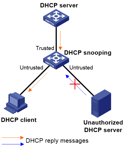
A. By default, the device specifies all ports that support DHCP snooping as untrusted ports after you enable DHCP snooping on it. The DHCP clients connected to the device will fail to obtain an IP address from an authorized DHCP server. To address this issue, do the following for the DHCP snooping device to ensure correct DHCP reply forwarding from server to client:
1. As shown in Figure 11, specify the ports connected to authorized DHCP servers as trusted ports.
2. Make sure the trusted ports and the ports connected to DHCP clients are in the same VLAN.
Figure 11 Trusted ports and untrusted ports
Q. Is there any difference between Comware 5 and Comware 7 in DHCP server configuration for IP assignment to clients on a private network?
A. On a Comware 5 device that acts as a DHCP server, you do not need to bind a VPN instance to an IP pool for its clients to obtain IP addresses from the DHCP server.
On a Comware 7 device that acts as a DHCP server, you must bind a VPN instance to an IP pool for its client to obtain IP addresses from the DHCP server. For example, you must bind VPN instance abc to an IP pool for the clients in the VPN instance to obtain IP addresses. This is because Comware 7 divides networks into the public network and private networks for DHCP to provide better services. If you do not bind a pool to a VPN instance, IP addresses in that pool can be assigned only to clients on the public network.
Q. What should I do to have the DHCP server or relay agent settings take effect?
A. To have the DHCP server or relay settings take effect, you must execute the dhcp enable command in system view to enable DHCP globally.
Q. Does DHCP snooping record IP address and MAC address bindings for DHCP clients by default?
A. No. By default, DHCP snooping does not record client information in DHCP snooping entries. If you are using IP source guard or any other features that require DHCP snooping entries, execute the dhcp snooping binding record command in the following views as needed:
· System view
· VLAN view
· VSI view
· Interface view
DHCP snooping and recording of client information in DHCP snooping entries might be unavailable in some of the view, depending on the device model.
Q. What restrictions and guidelines should I follow when I change the IP range for dynamic allocation in a DHCP pool?
A. You can use the address range command to change the IP range for dynamic allocation in a DHCP pool. To have a successful configuration, make sure the new IP range contains the IP addresses that have been allocated from the pool. To use a new IP range that does not contain some of the IP addresses that have been allocated from the pool, do the following:
1. Use the reset dhcp server ip-in-use command to release all allocated IP addresses.
2. Use the address range command again to specify the new IP range for the pool.
Q. What ports should I configure as trusted ports on a DHCP snooping device?
A. A DHCP client would be unable to communicate with other hosts if it obtained an invalid IP address and network settings from an unauthorized DHCP server. To address this issue, configure ports facing authorized DHCP servers as trusted ports on a DHCP snooping device. This operation ensures that DHCP clients can obtain IP addresses only from the authorized DHCP servers.
Q. How do I bind a client ID or MAC address to an IP address on a switch acting as a DHCP server?
A. You can use the static-bind ip-address command in IP pool view to bind the client ID or MAC address of a client to an IP address. On receipt of a DHCP request from the client, the switch will assign the bound IP address to the client. For example, bind IP address 10.1.1.1/24 to client 10.1.1.1/24 in pool 0.
<Sysname> system-view
[Sysname] dhcp server ip-pool 0
[Sysname-dhcp-pool-0] static-bind ip-address 10.1.1.1 mask 255.255.255.0 client-identifier 00aa-aabb
The IP addresses of some devices, such as the gateway and FTP server, cannot be assigned to clients. To avoid IP address conflict, perform one of the following tasks:
· Use the dhcp server forbidden-ip command in system view to exclude such addresses from DHCP allocation globally on the DHCP server.
· Use the forbidden-ip command in IP pool view to exclude such addresses from DHCP allocation in an IP pool on the DHCP server.
Q. Why does the DHCP server fail to assign some IP addresses on a DHCP snooping network?
A. The DHCP snooping feature records information about a client in a snooping entry. This entry includes MAC address of the client, IP address assigned to the client, client-facing port on the DHCP snooping device, and VLAN. Some security features (such as IP source guard) use the snooping entries on the DHCP snooping device to provide specific security functionality.
The DHCP snooping device might receive an IP address request from a client with a MAC address already recorded in a snooping entry. In this situation, the DHCP snooping device cannot determine whether the client is a legal DHCP user, because of the application of specific security features. As a result, the DHCP snooping device does not update the snooping entry generated for that MAC address and the client cannot obtain an IP address. To resolve this issue, delete the snooping entry generated for that MAC address.
IP services
This section contains the most frequently asked questions about IP services.
Q. Why does the Web management page of a switch suddenly close after I connect another switch to the LAN?
A. This issue might be caused by an IP address conflict. Some switches support Web-based login by default and their VLAN-interface 1 has a default management IP address.
Management IP conflict typically occurs when multiple switches with the same default management IP address were deployed on the same LAN, with their management IP addresses unchanged. This conflict might cause Web management page login failure or sudden close of the Web management page. To address this issue, do the following:
1. Log in to the switch on the Console interface.
2. Use the ip address command to configure a new IP address and mask for interface VLAN-interface 1. Make sure the new IP address is a unique IP address in the subnet for the LAN.
|
|
NOTE: You can obtain the default management IP address on the device nameplate. The default mask is 255.255.255.0. |
Q. What should I do if I can ping an IP address but I cannot open the webpage at that IP address?
A. If you experience a slow response or are unable to access a Web service when network connectivity is available, check for the following issues:
· Link congestion—To reduce congestion, apply a QoS policy or configure traffic congestion management settings.
· Firewall configuration—Make sure the firewall does not block Web services.
· Small TCP MSS—To set an appropriate TCP MSS value, use the tcp mss value command. Typically, TCP MSS is set to 1460 bytes.
Q. Why am I disconnected every time after I Telnet to the device?
A. This issue occurs when one of the following conditions exists:
· The physical link is unstable.
· Interface failure occurs.
· IP address conflict exists.
Q. What will happen if IP conflict occurs?
A. IP conflict typically leads to a communication failure. The following are common issues that might result from an IP conflict:
· The device cannot ping another device successfully.
· The device cannot be pinged by another device successfully.
· You cannot log in to the Web management page of the device.
· The Web management page of the device closes suddenly after your login.
· Telnet connection to the device is unstable.
· Abnormal disconnection occurs when you use FTP or TFTP to transfer files.
Q. How do I handle the packet loss issue that occurs when the device pings the gateway?
A. To resolve this issue:
1. Verify that ARP on the device has learned the MAC address of the gateway correctly by using the display arp command.
¡ If the MAC address in the ARP entry for the gateway is correct, go to step 4.
¡ If the MAC address in the ARP entry for the gateway is incorrect, this issue might result from an IP address error. Go to step 2.
2. Verify that the IP address settings of the device are correct. This issue might occur when one of the following conditions exists:
¡ The subnet mask is incorrect.
¡ The IP address of the device does not belong to the same subnet as the gateway IP address.
If the subnet or IP address is incorrect, specify the correct subnet or a correct IP address for the device.
3. Verify that the IP address of the device is unique on the LAN and no IP conflict exists on the LAN.
4. Check for link issues, such as link protocol exception, physical interface failure, or link disconnection.
5. If the issue persists, identify the point of failure in the path between the device and the gateway by using a packet capturer or traffic accounting tool for network issue analysis.
Q. How do I enable two hosts in the same subnet but on different physical network to exchange ARP packets?
A. Enable proxy ARP on the device.
Proxy ARP enables the device to reply to ARP requests sent from one host to another if they are in the same subnet but on different physical networks. With proxy ARP, hosts on different broadcast domains can communicate with each other as they would on the same broadcast domain.
Proxy ARP includes common proxy ARP and local proxy ARP:
· Common proxy ARP allows communication between hosts that connect to different Layer 3 interfaces and reside in different broadcast domains. To enable this feature, use the proxy-arp enable command in interface view.
· Local proxy ARP allows communication between hosts that connect to the same Layer 3 interface but reside in different broadcast domains. To enable this feature, use the local-proxy-arp enable [ ip-range start-ip-address to end-ip-address ] command in interface view.
Q. How do I configure an IP address for an Ethernet port on a Layer 2 switch?
A. You cannot configure an IP address for an Ethernet port on a Layer 2 switch. On a Layer 2 switch, you can only add ports to a VLAN, create the VLAN interface, and then assign an IP address to that VLAN interface. For example, add GigabitEthernet 1/0/1 to VLAN 10 and assign IP address 192.168.1.2/24 to VLAN-interface 10.
# Create VLAN 10.
[Switch] vlan 10
[Switch-vlan10] quit
# Add GigabitEthernet 1/0/1 to VLAN 10.
[Switch] interface gigabitethernet 1/0/1
[Switch-GigabitEthernet1/0/1] port access vlan 10
[Switch-GigabitEthernet1/0/1] quit
# Create VLAN-interface 10 and assign IP address 192.168.1.2/24 to the interface.
[Switch] interface vlan-interface 10
[Switch-vlan-interface10] ip address 192.168.1.2 24
Q. What restrictions and guidelines should I follow when I configure a static ARP entry?
A. When you configure a static ARP entry, follow these restrictions and guidelines:
· Make sure the IP address and the MAC address in the entry are mapped correctly.
· A static ARP entry cannot be overwritten by a dynamic ARP entry. You must manually maintain the static ARP entry when one of the events occurs:
¡ Link associated with the mapping entry fails.
¡ The interface associated with the entry has been changed.
· A static ARP entry does not age out. You must configure it manually. If the ARP table size supported by the device is small, configure as few static ARP entries as possible to make space for dynamic ARP entry learning. When the device or the interface associated with a static ARP entry is removed from the network, delete the static ARP entry immediately.
Access authentication
This section contains the most frequently asked questions about access authentication.
Q. In what order does the device select an authentication domain for an access user?
A. The device selects an authentication domain for an access user in the following order:
1. The authentication domain specified for the access module.
¡ For 802.1X authentication, the authentication domain is specified by using the dot1x mandatory-domain command in interface view.
¡ For MAC authentication, the authentication domain is specified by using the mac-authentication domain command in system view or interface view. The authentication domain specified in interface view takes precedence over that specified in system view.
¡ For portal authentication, the authentication domain is specified by using the portal domain command or the portal ipv6 domain command in interface view.
2. The ISP domain included in the username.
3. The default ISP domain of the device. To view the default ISP domain, use the display domain command. The Default domain name field displays the name of the default ISP domain.
If the selected domain does not exist on the device, the device searches for the ISP domain specified by using the domain if-unknown command. If no such ISP domain is configured, user authentication fails.
Q. How do I change the default ISP domain to another ISP domain or delete the default ISP domain?
A. To change the default ISP domain to another ISP domain:
1. Execute the display domain command and check the Default domain name field for the name of the current default ISP domain.
2. Execute the domain isp-name command to enter the view of the current default ISP domain. Then, use the undo domain default enable command to change the ISP domain to a non-default ISP domain.
3. Execute the domain isp-name command to enter the view of an existing ISP domain, or create a new ISP domain and enter its view. Then, use the domain default enable command to configure the ISP domain as the default ISP domain.
To delete an ISP domain that has been specified as the default ISP domain, follow these restrictions and guidelines:
· An ISP domain cannot be deleted when it is the default ISP domain. Before you use the undo domain command to delete the ISP domain, change the domain to a non-default ISP domain by using the undo domain default enable command.
· You can modify the settings of the system-defined ISP domain system, but you cannot delete the domain.
Q. What is local authentication?
A. In local authentication, the access device acts as a server to authenticate users. To implement local authentication, create local users and configure user attributes (including the username, password, and service types) on the device. The local users and attributes are stored in the local user database on the device.
When a user accesses the device, the device authenticates the user by comparing the user information with the information stored in the local user database. If a matching user entry is found, the user passes local authentication.
Q. Can local authentication succeed for a local user if no service type is specified for the local user? How do I specify a service type for a local user and what service types does the device support?
A. Local authentication cannot succeed for a local user if no service type is specified for the local user. The service type attribute contains services that a user can use. When the device performs local authentication for a user, it checks the service types of that user. If no service type is specified for that user, the user cannot use any service. As a result, the device does not allow that user to pass local authentication.
By default, a local user is not allowed to use any services. You can specify a service type for a local user by using the service-type command in local user view. Repeat this command to specify multiple service types for the local user.
The following service types are available:
· FTP—Allows the user to use the FTP service.
· HTTP—Allows the user to use the HTTP service.
· HTTPS—Allows the user to use the HTTPS service.
· LAN access—Allows the user to use the LAN access service. The users are typically Ethernet users, for example, 802.1X and MAC authentication users.
· Portal—Allows the user to use the portal service.
· SSH—Allows the user to use the SSH service.
· Telnet—Allows the user to use the Telnet service.
· Terminal—Allows the user to use the terminal service and log in from a console port.
Q. Why should I configure the source IP address for outgoing RADIUS packets in RADIUS authentication?
A. A RADIUS server identifies an access device by its IP address and processes a RADIUS packet only when the source IP address of the packet is the IP address of a managed access device. You must make sure the source IP address of RADIUS packets that an access device sends is the IP address of that access device configured on the RADIUS server. If the IP addresses are not the same, use the nas-ip command to change the source IP address of outgoing RADIUS packets on the access device.
By default, no IP address is specified as the source IP address of outgoing RADIUS packets. The source IP address of RADIUS packets is the primary IPv4 address or IPv6 address of the packet outbound interface.
Q. What methods can I use to specify a source IP address for outgoing RADIUS packets? What restrictions and guidelines should I follow when I specify a source IP address for outgoing RADIUS packets?
A. On the access device, use one of the following methods to specify a source IP address for outgoing RADIUS packets:
· In the view of a RADIUS scheme, use the nas-ip { ipv4-address | interface interface-type interface-number | ipv6 ipv6-address } command. This command takes effect only on the RADIUS scheme and takes precedence over the source IP address configuration in system view.
· In system view, use the radius nas-ip { interface interface-type interface-number | { ipv4-address | ipv6 ipv6-address } [ vpn-instance vpn-instance-name ] } command. This command applies to all RADIUS schemes.
When you specify a source IP address for outgoing RADIUS packets, follow these restrictions and guidelines:
· The following configurations overwrite each other:
¡ The configuration of specifying a source interface to provide the source IP address.
¡ The configuration of directly specifying a source IP address.
· As a best practice, specify a loopback interface address as the source IP address for outgoing RADIUS packets to avoid RADIUS packet loss caused by physical port errors.
Q. In which scenarios can I use 802.1X online user handshake and what restrictions and guidelines should I follow when this feature is enabled?
A. Use the online user handshake feature to check the connectivity status of online 802.1X users. This feature prevents the device from being unaware of user offline events after users go offline because of exceptions. To enable this feature, use the dot1x handshake command. With this feature, the access device sends handshake requests (EAP-Request/Identity) to online users at the interval specified by the dot1x timer handshake-period command. If the device does not receive any EAP-Response/Identity packets from an online user after it has made the maximum handshake attempts, the device sets the user to offline state. To set the maximum handshake attempts, use the dot1x retry command.
When 802.1X online user handshake is enabled, follow these restrictions and guidelines:
· If the network has 802.1X clients that cannot exchange handshake packets with the access device, use the undo dot1x handshake command to disable the online user handshake feature. This operation prevents the 802.1X connections from being incorrectly torn down.
· To ensure online user handshake and new user authentication when a large number of users are present, set the following parameters to a large value:
¡ Handshake timer (set by using the dot1x timer handshake-period command).
¡ Maximum number of attempts to send an authentication request to a client (set by using the dot1x retry command).
Q. How do I enable the 802.1X online user handshake security feature?
A. Use the dot1x handshake secure command.
Q. What configuration restrictions exist for the 802.1X online user handshake security feature?
A. The online user handshake security feature is applicable only to the network that deploys the iNode client and IMC server for 802.1X authentication. It prevents users from using illegal client software to bypass iNode security check.
To have the online user handshake security feature take effect, make sure the online user handshake feature is enabled.
Q. In what situations should I enable the 802.1X online user handshake reply feature?
A. Use the online user handshake reply feature only if 802.1X clients will go offline without receiving EAP-Success packets from the device. By default, this feature is disabled.
When the 802.1X online user handshake feature is enabled, the access device sends handshake requests (EAP-Request/Identity) periodically to online 802.1X clients. The online clients respond to the requests with EAP-Response/Identity packets. Typically, the device does not reply to the clients' EAP-Response/Identity packets with EAP-Success packets. Some 802.1X clients will go offline if they do not receive the EAP-Success packets for handshake. To avoid this issue, enable the online user handshake reply feature by using the dot1x handshake reply enable command.
Q. What restrictions and guidelines should I follow when I configure authentication, authorization, and accounting settings on the device and server?
A. To ensure that users can successfully come online, make sure the authentication, authorization, and accounting settings on the device are consistent with those on the server.
The following are some common user online failure cases:
· A user fails to come online because of authorization failure. The server is configured to assign a VLAN by its name to a user. However, the VLAN name does not exist on the device.
· A user fails to come online because of inconsistent passwords on the device and the IMC server.
· A portal user fails to come online because of inconsistent keys on the device and the portal authentication server. In this case, packets from the device cannot pass packet check on the portal authentication server, so the portal authentication server rejects to push the authentication page to the device. To resolve this issue:
a. Use the display this command in portal authentication server view to identify whether the device has been configured with a key for communication with the portal authentication server.
b. Take measures depending on whether a key has been configured on the device for communication with the portal authentication server.
- If no key has been configured, configure a key.
- If a key has been configured, use the ip or ipv6 command in portal authentication server view to change the key. Alternatively, you can change the key on the portal authentication server.
Make sure the device and the portal authentication server use the same key for communication with each other.
Q. In what scenarios does the port security MAC move feature take effect and what is the use of this feature?
A. Port security MAC move takes effect in the following scenarios:
· Inter-port move on a device—An online user authenticated through 802.1X authentication, MAC authentication, or Web authentication moves between ports on the device. The user VLAN or authentication method might change or stay unchanged after the move.
· Inter-VLAN move on a port—An online user authenticated through 802.1X authentication, MAC authentication, or Web authentication moves between VLANs on a trunk or hybrid port. In addition, the packets that trigger authentication have VLAN tags.
Port security MAC move allows an authenticated online user on one port or VLAN to be reauthenticated and come online on another port or VLAN without going offline first. After the user passes authentication on the new port or VLAN, the system removes the authentication session of the user on the original port or VLAN.
If this feature is disabled, authenticated users must go offline first before they can be reauthenticated successfully on a new port or VLAN to come online.
Q. In what situation should I enable port security MAC move?
A. As a best practice to minimize security risks, enable MAC move only if user roaming between ports is required.
To enable port security MAC move, use the port-security mac-move permit command. By default, port security MAC move is disabled.
Q. Why cannot port security MAC move take effect?
A. This feature cannot take effect in the following situations:
· The maximum number of online users on the authentication server has been reached.
· MAC authentication multi-VLAN mode is enabled. This mode has higher priority than MAC move for users moving between VLANs on a port. If MAC authentication multi-VLAN mode is enabled, these users can come online in the new VLAN without being reauthenticated. To enable MAC authentication multi-VLAN mode, use the mac-authentication host-mode multi-vlan command.
Q. What benefits does an 802.1X mandatory domain have? How do I configure and view the 802.1X mandatory domain on a port?
A. You can place all 802.1X users in a mandatory authentication domain for authentication, authorization, and accounting on a port. No user can use an account in any other domain to access the network through the port. Per-port mandatory authentication domain deployment enhances the flexibility of 802.1X access control.
By default, no mandatory 802.1X authentication domain is specified. To specify a mandatory 802.1X authentication domain on a port, you can execute the dot1x mandatory-domain command in Layer 2 Ethernet interface view or Layer 2 aggregate interface view. Support for 802.1X on a Layer 2 aggregate interface depends on the device model.
To view the mandatory 802.1X authentication domain on a port, use the display dot1x command. The Mandatory auth domain field displays the mandatory 802.1X authentication domain settings.
Q. What are the default authentication, authorization, and accounting methods in an ISP domain if no authentication, authorization, or accounting methods are specified for the ISP domain?
A. The default authentication, authorization, and accounting methods in an ISP domain are local.
Q. How do I configure the default authorization methods?
A. In ISP domain view, you can use the following command to configure the default authorization methods:
authorization default { hwtacacs-scheme hwtacacs-scheme-name [ radius-scheme radius-scheme-name ] [ local ] [ none ] | local [ none ] | none | radius-scheme radius-scheme-name [ hwtacacs-scheme hwtacacs-scheme-name ] [ local ] [ none ] }
Q. Can I specify different RADIUS schemes for RADIUS authentication and authorization for the same type of users in an ISP domain?
A. No, you cannot. If both RADIUS authentication and authorization are used for the same type of users in an ISP domain, you must specify the same RADIUS scheme for RADIUS authentication and authorization. This ensures that the RADIUS authorization can take effect.
Q. Can I specify backup methods for authentication, authorization, or accounting in addition to the primary method?
A. Yes, you can specify multiple backup methods for authentication, authorization, or accounting in addition to the primary method.
When the primary authentication, authorization, or accounting method is invalid, the device attempts to use the backup authentication, authorization, or accounting methods in sequence. For example, the authorization default radius-scheme radius-scheme-name local none command specifies the default RADIUS authorization method and two backup methods (local authorization and no authorization). The device performs RADIUS authorization by default and performs local authorization when the RADIUS server is invalid. The device does not perform authorization when both of the previous methods are invalid.
Q. How do I configure the iNode client when it acts as the 802.1X client?
A. This example uses iNode PC 7.3 to describe the configuration procedure. The procedure is as follows:
1. Run the iNode client.
Figure 12 iNode client
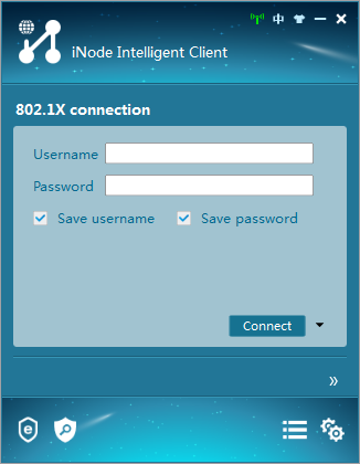
2. Create a new 802.1X connection.
3. On the New 802.1X Connection Wizard window, select a connection type, and then click Next.
Figure 13 Creating an 802.1X connection
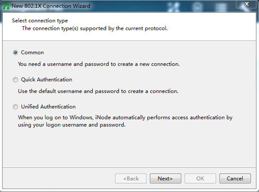
4. Enter the 802.1X connection name, username, and password, and then click Next.
Figure 14 Configuring the 802.1X connection name, username, and password
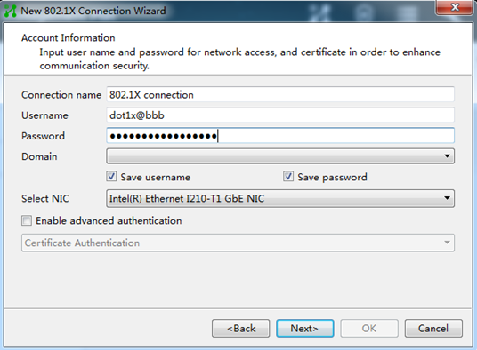
For authentication to be performed correctly, the following details must comply with the correlation rules shown in Table 3:
¡ Username specified on the iNode client.
¡ Domain and username format configuration on the access device.
¡ Service suffix on IMC.
|
Username format on the iNode client |
Domain on the access device |
Username format configured on the access device |
Service suffix on IMC |
|
X@Y |
Y |
with-domain |
Y |
|
X@Y |
Y |
without-domain |
No suffix |
|
X |
Default domain (the default domain specified on the access device) |
with-domain |
Name of the default domain |
|
X |
Default domain (the default domain specified on the access device) |
without-domain |
No suffix |
5. Configure the network property settings, and then click OK.
If you set local authentication as the backup authentication method, do not select Upload version info in the Run Mode area. The access device cannot recognize the version number in EAP packets.
Figure 15 Configuring 802.1X connection properties
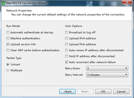
6. Initiate the 802.1X connection.
Enter the username and password on the iNode client, and then click Connect.
Q. What categories of security modes does port security support? How do I change the port security mode on a port?
A. Port security supports the following categories of security modes:
· MAC learning control—Includes two modes: autoLearn and secure. MAC address learning is permitted on a port in autoLearn mode and disabled in secure mode.
· Authentication—Security modes in this category implement MAC authentication, 802.1X authentication, or a combination of these two authentication methods.
To change the port security mode on a port, use the port-security port-mode command. By default, a port is in noRestrictions mode. In this mode, port security is disabled on the port and access to the port is not restricted.
Q. Before I set a port security mode for a port, what tasks should I complete?
A. Before you set a port security mode for a port, complete the following tasks:
· Disable 802.1X and MAC authentication.
· Verify that the port does not belong to a service loopback group.
· If you are configuring the autoLearn mode, set port security's limit on the number of secure MAC addresses. You cannot change the setting when the port is operating in autoLearn mode.
Q. How do I make an endpoint bypass authentication in an 802.1X environment?
A. For this purpose, use the mac-address static command to bind the MAC address of the endpoint to the 802.1X-enabled port connected to the endpoint. By default, no static MAC address is bound to a port.
For example, the MAC address of an endpoint is 0001-0001-0001 and the endpoint is connected to GigabitEthernet 1/0/1 on a switch. GigabitEthernet 1/0/1 belongs to VLAN 10. You can execute the mac-address static 0001-0001-0001 interface gigabitethernet 1/0/1 vlan 10 command in system view to bind the endpoint MAC address to the port. The command makes the endpoint bypass authentication.
Q. What Login-Service attribute check methods does the device support for SSH, FTP, and terminal users? How do I configure the Login-Service attribute check method for these users?
A. The device supports the following check methods for the Login-Service attribute (RADIUS attribute 15) of SSH, FTP, and terminal users:
· Strict—Matches Login-Service attribute values 50, 51, and 52 for SSH, FTP, and terminal services, respectively.
· Loose—Matches the standard Login-Service attribute value 0 for SSH, FTP, and terminal services.
To configure the Login-Service attribute check method for SSH, FTP, and terminal users, execute the attribute 15 check-mode { loose | strict } command in RADIUS scheme view.
On the device, a RADIUS Access-Accept packet received for a user must contain the matching attribute value. Otherwise, the user cannot log in to the device. As a best practice, use the loose check method only when the server does not issue Login-Service attribute values 50, 51, and 52 for SSH, FTP, and terminal users.
Q. In what order does the device select a reauthentication interval for an 802.1X user?
A. When the device periodically reauthenticates an 802.1X user, it selects a reauthentication interval for the user in the following order:
1. Reauthentication interval assigned by the server.
2. Reauthentication interval configured by using the dot1x timer reauth-period command in interface view.
3. Reauthentication interval configured by using the dot1x timer reauth-period command in system view.
4. The default reauthentication interval, which is 3600 seconds.
Q. What is a free IP?
A. A free IP is a freely accessible network segment, which has a limited set of network resources such as software and DHCP servers. To ensure security policy compliance, an unauthenticated user can access only this segment to perform operations. For example, the user can download EAD client from a software server or obtain a dynamic IP address from a DHCP server. To configure a free IP, use the dot1x ead-assistant free-ip command.
Q. Can I use 802.1X free IPs in conjunction with port security?
A. No, you cannot. If you enable port security, EAD assistant free IPs cannot take effect. As a best practice, do not use 802.1X free IPs in conjunction with port security.
Q. Can I use 802.1X EAD assistant in conjunction with MAC authentication and what restrictions and guidelines should I follow when I configure both 802.1X EAD assistant and MAC authentication?
A. Whether 802.1X EAD assistant can be used in conjunction with MAC authentication depends on the device model and software version. For more information, see 802.1X configuration in Security Configuration Guide for the device and software version.
When you use both 802.1X EAD assistant and MAC authentication, follow these restrictions and guidelines:
· If both EAD assistant and MAC authentication are configured, the device does not mark the MAC address of a user that has failed MAC authentication as a silent MAC address. If the user has never passed MAC authentication, packets from the user can trigger MAC authentication again only after the user's EAD entry ages out.
· As a best practice, do not configure MAC authentication guest VSIs, guest VLANs, critical VSIs, or critical VLANs. The VLANs or VSIs might fail to work correctly when both EAD assistant and MAC authentication are configured on the device.
· As a best practice, do not configure the Web authentication or IP source guard feature. These features might fail to work correctly when both EAD assistant and MAC authentication are configured on the device.
· If the MAC address of a user has been marked as a silent MAC address before you enable EAD assistant, packets from the user can trigger EAD assistant only after the quiet timer expires.
Q. Why cannot I use the portal delete-user command on the access device to log out a portal user, but the portal user can log out by clicking the Disconnect button on the portal authentication client? How do I resolve this issue?
A. When you execute the portal delete-user command on the access device to log out a portal user, the access device sends an unsolicited logout notification message to the portal authentication server. If the destination port in the logout notification is different from the listening port on the portal authentication server, the server cannot receive the notification. As a result, the portal authentication server does not log out the portal user.
When a user uses the Disconnect button on the authentication client to log out, the portal authentication server sends an unsolicited logout request message to the access device. The access device uses the source port in the logout request as the destination port in the logout ACK message. As a result, the portal authentication server can definitely receive the logout ACK message and log out the user.
To resolve this issue:
1. Execute the display portal server command to view the listening port number of the portal authentication server configured on the access device.
2. Execute the portal server command in system view to change the listening port number of the portal authentication server on the access device. Make sure the listening port number of the portal authentication server on the access device is the same as the listening port number on the portal authentication server. By default, the listening port number on the portal authentication server is 50100.
Q. In what situation should I enable an authentication trigger?
A. If the client cannot send EAPOL-Start packets to initiate 802.1X configuration, enable an authentication trigger on the access device to initiate authentication.
The access device supports the following trigger modes:
· Multicast trigger mode—The access device multicasts EAP-Request/Identity packets to initiate 802.1X authentication at the identity request interval.
· Unicast trigger mode—Upon receiving a frame from an unknown MAC address, the access device sends an EAP-Request/Identity packet out of the receiving port to the MAC address. The device retransmits the packet if no response has been received within the identity request timeout interval. This process continues until the maximum number of request attempts set by using the dot1x retry command is reached.
To set the identity request interval for the multicast trigger and the identity request timeout interval for the unicast trigger, use the dot1x timer tx-period command.
By default, multicast trigger is enabled and unicast trigger is disabled.
To avoid duplicate authentication packets, do not enable both triggers on a port.
Q. What is the 802.1X critical VLAN on a port and in what situation is a port assigned to the critical VLAN?
A. The 802.1X critical VLAN on a port accommodates 802.1X users that have failed authentication because none of the RADIUS servers in their ISP domain are reachable. Users in the critical VLAN can access a limited set of network resources depending on the configuration.
The critical VLAN feature takes effect when 802.1X authentication is performed only through RADIUS servers. If an 802.1X user fails local authentication after RADIUS authentication, the user is not assigned to the critical VLAN.
Q. For which purposes can I set the maximum number of secure MAC addresses allowed by port security on a port?
A. Port security allows multiple users to access a port. However, the number of users cannot exceed the upper limit on the port. You can set the maximum number of secure MAC addresses that port security allows on a port for the following purposes:
· Controlling the number of concurrent users on the port.
For a port operating in a security mode (except for autoLearn and secure), the upper limit equals the smaller of the following values:
¡ The limit of the secure MAC addresses that port security allows. The limit is set by using the port-security max-mac-count max-count [ vlan [ vlan-id-list ] ] command.
¡ The limit of concurrent users allowed by the authentication mode in use. For 802.1X authentication, the limit is set by using the dot1x max-user max-number command. For MAC authentication, the limit is set by using the mac-authentication max-user max-number command.
· Controlling the number of secure MAC addresses on the port in autoLearn mode.
You can also set the maximum number of secure MAC addresses that port security allows for specific VLANs or each VLAN on a port.
Q. How do I enable guest VLAN or VSI reauthentication in MAC authentication?
A. To enable guest VLAN reauthentication in MAC authentication, use the mac-authentication guest-vlan re-authenticate command. By default, this feature is enabled.
To enable guest VSI reauthentication in MAC authentication, use the mac-authentication guest-vsi re-authenticate command. By default, this feature is enabled.
Q. How do I set the authentication interval for users in the MAC authentication guest VLAN or guest VSI on a port if a large number of endpoints access the port to perform MAC authentication?
A. As a best practice, set the reauthentication interval to a value greater than 30 seconds if the number of concurrent MAC authentication users on a port is likely to exceed 300. To set the authentication interval for users in the MAC authentication guest VLAN, use the mac-authentication guest-vlan auth-period command. To set the authentication interval for users in the MAC authentication guest VSI, use the mac-authentication guest-vsi auth-period command.
Q. What is IP source guard? From what modules can IP source guard obtain dynamic bindings?
A. IP source guard (IPSG) prevents spoofing attacks by using an IPSG binding table to filter out illegitimate packets. This feature is typically configured on user-side interfaces. IPSG bindings can be static or dynamic.
Dynamic IPv4SG or IPv6SG generates dynamic bindings from the source modules specified by using the ip verify source or ipv6 verify source command.
Table 4 Source modules for dynamic IPSG bindings
|
Interface type |
Source modules for dynamic IPv4SG bindings |
Source modules for dynamic IPv6SG bindings |
|
Layer 2 Ethernet interface |
DHCP snooping and ARP snooping |
DHCPv6 snooping and ND snooping |
|
802.1X |
802.1X |
|
|
Layer 3 Ethernet interface or VLAN interface |
DHCP relay agent |
DHCPv6 relay agent and ND RA |
|
DHCP server |
DHCPv6 server |
To ensure dynamic generation of IPSG bindings, you must enable the 802.1X, ARP snooping, ND snooping, DHCP or DHCPv6 snooping, DHCP or DHCPv6 relay agent, DHCP or DHCPv6 server, or ND RA feature. In addition, make sure the configuration for the feature is valid and the feature can operate correctly.
Q. Why cannot IPv4SG take effect after static IPv4SG bindings are configured?
A. To configure static IPv4SG bindings, execute the ip source binding command in system or interface view. By default, IPv4SG bindings cannot filter packets on interfaces immediately after they are configured. To enable IPv4SG bindings to filter incoming packets on an interface, you must also execute the ip verify source command on the interface. Then, the device uses the configured static IPv4SG bindings and dynamic IPv4SG bindings obtained from other modules to filter incoming packets on the interface or cooperate with other modules for security services.
Q. Why cannot portal HTTPS redirect take effect?
A. Web redirect redirects the HTTP or HTTPS requests of users to the specified URL. The device can directly redirect HTTP requests without any configuration. For the device to redirect HTTPS requests, you must configure an HTTPS redirect listening port number. Make sure the port number is not a well-known port number or used by other TCP-based services.
To display port numbers used by TCP-based services, use the display tcp command.
The default HTTPS redirect listening port number on the device is 6654. To change the HTTPS redirect listening port number, use the http-redirect https-port command.
Q. Why must I configure shared keys for exchanging RADIUS packets between the access device and RADIUS servers?
A. The RADIUS client (the device) and a RADIUS server exchange information between them with the help of shared keys. A RADIUS packet contains a field that includes a signature generated by using the MD5 algorithm, the shared key, and some other information. The receiver of the packet verifies the signature and accepts the packet only when the signature is correct. This mechanism ensures the security of information exchanged between the RADIUS client and server.
Typically, specify a shared key when you configure a primary or secondary RADIUS authentication or accounting server on the device. To configure a RADIUS server on the device, use the primary accounting, primary authentication, secondary accounting, or secondary authentication command. If you do not specify a shared key when using one of the commands, use the key command in RADIUS scheme view to specify a shared key for authentication or accounting packets.
Make sure the shared key specified for a RADIUS server on the device is the same as that configured on the RADIUS server.
Q. Do I need to configure accounting methods in an ISP domain if no accounting servers are available?
A. The default accounting method in an ISP domain is local. To avoid user authentication failure, use the accounting default none command to configure the ISP domain by default to not perform accounting.
Q. Can the RADIUS authentication, authorization, or accounting method take effect in an ISP domain if the RADIUS scheme specified for the RADIUS authentication, authorization, or accounting method does not exist?
A. The RADIUS authentication, authorization, or accounting method cannot take effect in an ISP domain if the RADIUS scheme specified for the RADIUS authentication, authorization, or accounting method does not exist. To examine whether a RADIUS scheme exists, use the display radius scheme command. The following information shows an example:
[system] domain aaa
[system-isp-aaa] authentication login radius-scheme bbb
[system-isp-aaa] display radius scheme bbb
The RADIUS scheme does not exist.
The output shows that RADIUS scheme bbb does not exist. The authentication method specified for login users in ISP domain aaa cannot take effect.
Q. How can I configure settings to make an IMC server to deploy an authorization ACL to the device for a user?
A. In addition to specify the authorization ACL on the IMC server, you must use the radius session-control enable command on the device to enable RADIUS session-control.
An IMC RADIUS server uses session-control packets to send dynamic authorization change requests (including authorization ACL, VLAN, user group, VSI, and blackhole MAC change requests) and disconnect requests to the device. If an IMC RADIUS server is used and the server dynamically changes authorization information for users or disconnects users, you must enable RADIUS session-control on the device.
Q. Why the reauthentication period becomes so long for users when 802.1X online user synchronization is enabled and a number of 802.1X users are online? What should I do to resolve the issue?
A. When 802.1X online user synchronization is enabled, the amount of time required to complete online user synchronization increases as the number of online users grows. This might result in an increased delay for new 802.1X users and users in the critical VLAN or VSI to authenticate or reauthenticate to the RADIUS server and come online.
To resolve this issue, execute the undo dot1x server-recovery online-user-sync command to disable 802.1X online user synchronization.
Q. What measures can I take to resolve the issue that a user cannot come online again after it goes offline because the device is unaware of its offline?
A. Use one of the following methods:
· Execute the dot1x offline-detect enable command to enable port-specific 802.1X offline detection. The 802.1X offline detection feature monitors the online status of 802.1X users. This feature uses an offline detect timer to set the interval that the device must wait for traffic from a user before the device determines that the user is idle. If the device has not received traffic from a user before the timer expires, the device logs off that user and requests the accounting server to stop accounting for the user.
· Execute the port-security traffic-statistics enable command to enable traffic statistics for 802.1X and MAC authentication users. This command enables the device to collect and send traffic statistics of 802.1X users based on their MAC addresses to the accounting server in addition to their online duration. Support for this command depends on the device model.
· Execute the port-security mac-move permit command to enable port security MAC move. Port security MAC move allows an authenticated online user on one port to be reauthenticated and come online on another port without going offline first. After the user passes authentication on the new port, the system removes the authentication session of the user on the original port. This action ensures that the user stays online on only one port.
Q. What should I do before I configure the 802.1X guest VLAN on a port?
A. Before you configure the 802.1X guest VLAN on a port, complete the following tasks:
· Create the VLAN to be specified as the 802.1X guest VLAN.
· If the 802.1X-enabled port performs MAC-based access control, perform the following operations for the port:
¡ Configure the port as a hybrid port.
¡ Enable MAC-based VLAN on the port. For more information about MAC-based VLANs, see Layer 2—LAN Switching Configuration Guide.
· If the port type is hybrid, verify that the VLAN to be specified as the guest VLAN is not in the tagged VLAN list on the port.
Q. Can I enable unicast trigger on a port if that port performs port-based access control?
A. As a best practice, enable unicast trigger only on ports that perform MAC-based access control. If you enable unicast trigger on a port that performs port-based access control, users might fail to come online on that port.
In addition, to avoid duplicate authentication packets, do not enable both unicast and multicast triggers on a port.
Q. How do I configure the user account format for MAC authentication users?
A. By default, the MAC addresses of users are used as their usernames and passwords for MAC authentication. The MAC addresses used as usernames and passwords are in hexadecimal notation without hyphens, and letters in the MAC addresses are in lower case.
To change the user account format for MAC authentication users, use the mac-authentication user-name-format command. To ensure successful authentication, make sure the format of the user accounts configured on the device for local authentication or on a remote server for remote authentication is compliant with the user account format specified on the device.
For users in a MAC address range, the MAC address range-specific user account (configured by using the mac-authentication mac-range-account command) has higher priority than the global user account setting (configured by using the mac-authentication user-name-format command). By default, no username or password is configured for a MAC address range. The global user account policy applies to MAC authentication users.
Q. How do 802.1X authentication and MAC authentication relate to port security?
A. To enable port security, you must disable 802.1X and MAC authentication globally.
When port security is enabled, you cannot enable 802.1X or MAC authentication on a port, or change the access control mode or port authorization state of an 802.1X port. Port security automatically modifies these settings in different security modes.
To disable port security, use the undo port-security enable command. Because this command logs off online users, make sure you understand the impact of this operation on services when you do that.
Enabling or disabling port security resets the following security settings to the default:
· 802.1X access control mode, which is MAC-based by default.
· Port authorization state, which is auto by default.
Q. How do I change port security mode?
A. Port security is available on Layer 2 Ethernet interfaces and Layer 2 aggregate interfaces. To change the port security mode of a Layer 2 Ethernet or aggregate interface, execute the port-security port-mode command in its interface view. By default, a port operates in noRestrictions mode. In this mode, port security is disabled on the port and network access through the port is not restricted.
When port security is enabled, you can change the port security mode of a port only when the port is operating in noRestrictions (the default) mode. To change the port between any other two modes, you must first use the undo port-security port-mode command to restore the default port security mode.
You cannot change the port security mode of a port when it has online users.
Before you set the port security mode of a port, disable 802.1X and MAC authentication on that port. In addition, do not change the default 802.1X access control mode or authorization state on the port.
Routing
This section contains the most frequently asked questions about routing.
Q. What issues might occur when the route configuration is incomplete or incorrect and how do I resolve the issues?
A. The following issues might occur when the route configuration is incomplete or incorrect:
· A switch or host cannot ping IP addresses in a different network.
· A host cannot access the webpage of a switch in a different network.
· A device directly connected to a switch cannot access external networks.
· A switch cannot learn ARP entries for devices in a different network.
· A switch can only send or receive packets.
To resolve this issue:
1. Verify that all links in the network are running correctly, the IP addresses of all devices are configured correctly, and no network conflict occurs.
2. If a host cannot access devices in a different network through a switch, verify that the host is configured with a correct gateway address.
3. If a switch cannot access devices in a network, verify that the following routes have been configured:
¡ A route destined for the network has been configured on the switch.
¡ Routes destined for the source and destination addresses have been configured on the intermediate device.
¡ A route destined for the source address has been configured on the destination device.
For example, as shown in Figure 16, Host A cannot communicate with Server B if you only configure a route destined for network 10.2.2.0/24 on Switch A. To resolve this issue, you must also configure a route destined for 10.1.1.0/24 on Switch B.
Figure 16 Layer 3 communication
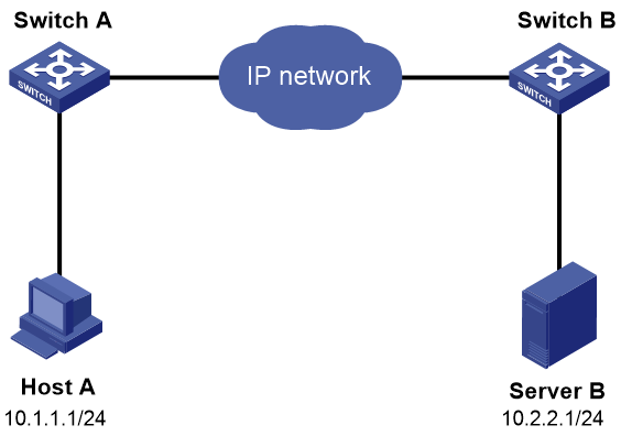
Q. Can I configure the same network address for a VPN and the public network on a device?
A. No, you cannot. Such configuration will cause packet forwarding failures, because other devices will select the next hop of the direct route to the device instead of the next hop of the static route configured for the VPN.
Q. What will happen if PBR configuration errors exist and how do I resolve the issue?
A. Packet forwarding failures might occur if PBR configuration errors exist, because packets matching the PBR policy are preferentially forwarded based on the policy.
To resolve this issue:
1. Execute the display ip policy-based-route command to verify that a PBR policy has been configured.
2. Execute the display ip policy-based-route setup command to view PBR configuration, and then execute the following commands to view different types of PBR information:
¡ Execute the display ip policy-based-route local command to view local PBR configuration and statistics.
¡ Execute the display ip policy-based-route interface command to view interface PBR configuration and statistics.
¡ Execute the display ip policy-based-route apply command to view the PBR configuration and statistics for a VLAN interface.
¡ Execute the display ip policy-based-route global command to view information about global PBR, including its configuration and statistics.
¡ Execute the display ip policy-based-route egress interface command to view the outbound PBR configuration and statistics for a VXLAN tunnel interface.
3. If a PBR policy node contains an if-match clause that uses an ACL match criterion, execute the display acl command to display ACL configuration and match statistics.
4. Edit the PBR configuration as follows:
¡ If an if-match or apply clause is incorrect, edit the if-match or apply clause.
¡ If the PBR policy was applied to the wrong interface, remove the policy from the interface, and then apply the policy to the correct interface.
¡ If the applied global or local PBR policy has configuration errors, remove the policy, edit the policy, and then apply the policy again.
Q. Can I specify an interface that is not up as the output interface for a static route?
A. No, you cannot. If you specify an interface that is not up as the output interface for a static route, the static route does not take effect.
Q. Can a device communicate with devices in other networks without a gateway configured for it?
A. No, it cannot. To enable a device to communicate with devices in other networks, you must configure a gateway for the device and configure routes on indirectly connected gateways.
Q. The backup static route does not take over in time to forward packets when the primary link fails. Why does this happen, and how do I resolve the issue?
A. This issue might be caused by the failure of the device to detect the primary link failure in time. To resolve this issue, associate a static route with a track entry associated with an NQA reaction entry. When the primary link fails, NQA can detect the failure in time. The device can then withdraw the primary static route and use the backup static route for packet forwarding.
Q. What should I do when the detection module associated with the track entry configured for a static route fails to detect link failures?
A. To resolve this issue:
1. Verify that the configuration on the detection module is correct.
2. Verify that the static route has been associated with the track entry successfully and the static route configuration is correct.
You can execute the display current-configuration | include route-static command to view the static route configuration. When you configure a static route, make sure the command parameters are configured as described in the command reference. Make sure no parameters are configured after the description keyword.
Q. What are the common causes for BGP peer establishment failures and how do I resolve the issue?
A. Common causes for BGP peer establishment failures include:
· BGP packet forwarding failure occurs.
· TCP port 179 is disabled by ACL.
· The AS number of the peer is incorrectly configured.
· The IPv4/IPv6 address of the peer is incorrectly configured.
· The peer enable command is not executed.
· The loopback interface is used but the peer connect-interface command is not executed.
· The peer is an indirect EBGP peer but the peer ebgp-max-hop command is not executed.
· The configuration of the peer ttl-security hops command is incorrect.
· The peer ignore command is executed.
· The two ends have inconsistent address family capabilities.
To resolve this issue:
1. Execute the ping command to verify the connectivity to the peer.
2. Verify that a valid route to the peer is available.
3. Execute the display tcp verbose or display ipv6 tcp verbose command to verify that the TCP connection is running correctly.
4. Verify that no ACL rule is applied to disable TCP port 179.
5. Execute the display current-configuration command to verify that the peer's AS number is correct.
6. Execute the display bgp peer ipv4 unicast or display bgp peer ipv6 unicast command to verify that the peer's IPv4/IPv6 address is correct.
7. If a loopback interface is used, verify that the peer connect-interface command has been executed.
8. If the peer is an indirect EBGP peer, verify that the peer ebgp-max-hop command has been executed.
9. If the peer ttl-security hops command has been executed on the local end, verify that the command has also been executed on the remote end. Verify that the hop counts configured on the local and remote ends are larger than the number of actual hops between them.
10. Verify that the peer ignore command is not executed on the local or remote end.
If the peer ignore command has been executed, you can execute the undo peer ignore command to remove the configuration.
11. Verify that the local and remote ends have the same address family capabilities. For example, to establish BGP VPNv4 peer relationship, you must execute the peer enable command in BGP-VPNv4 address family view on both the local and remote ends.
Q. How do I view and set the maximum number of ECMP routes supported by the system?
A. To view the maximum number of ECMP routes supported by the system, perform the following tasks:
· To view the maximum number of IPv4 ECMP routes supported by the system, execute the display max-ecmp-num command.
· To view the maximum number of IPv6 ECMP routes supported by the system, execute the display ipv6 max-ecmp-num command.
To set the maximum number of ECMP routes supported by the system, perform the following tasks:
· To set the maximum number of IPv4 ECMP routes supported by the system, execute the max-ecmp-num command.
· To set the maximum number of IPv6 ECMP routes supported by the system, execute the ipv6 max-ecmp-num command.
After the number of ECMP routes reaches the limit, new ECMP routes cannot share load with existing ECMP routes.
Some devices do not support configuring the maximum number of ECMP routes supported by the system. In this scenario, you can execute the maximum load-balancing command in the corresponding routing protocol view to view the maximum number of ECMP routes supported by the routing protocol. The ECMP route mode might affect the number of ECMP routes. To edit the ECMP route mode, execute the ecmp mode command. For more information about ECMP routes, see basic IP routing configuration in Layer 3—IP Routing Configuration Guide.
Q. How do I interconnect different VPN instances or interconnect a VPN instance and the public network through Layer 3 interfaces?
A. You can perform one of the following tasks to interconnect different VPN instances or interconnect a VPN instance and the public network through Layer 3 interfaces:
· Configure static routes:
¡ To interconnect two VPN instances, execute the ip route-static vpn-instance command with the two VPN instances specified as the source and destination VPN instances.
¡ To interconnect a VPN instance and the public network, perform the following tasks:
- Execute the ip route-static vpn-instance command with an IP address in the public network specified as the next hop.
- Execute the ip route-static command with an IP address in the VPN instance specified as the next hop.
· Configure BGP routes—Execute the import-route command to redistribute IGP routes in different VPN instances.
· Configure route replication:
¡ Execute the route-replicate command in VPN instance IPv4 address family view to redistribute routes in the public network or a VPN instance to the specified VPN instance.
¡ Execute the route-replicate command in public network IPv4 address family view to redistribute routes in a VPN instance to the public network.
Q. Why do IPv6 routes with a prefix longer than 64 bits not take effect on a device?
A. IPv6 routes with a prefix longer than 64 bits take effect on some devices only after you enable the devices to support IPv6 routes with a prefix longer than 64 bits and restart the devices.
· On some devices, execute the display switch-routing-mode status command to verify whether the devices support IPv6 routes with a prefix longer than 64 bits, and execute the switch-routing-mode ipv6-128 command to enable the devices to support IPv6 routes with a prefix longer than 64 bits.
· On some devices, execute the display hardware-resource routing-mode command to verify whether the devices support IPv6 routes with a prefix longer than 64 bits, and execute the hardware-resource routing-mode ipv6-128 command to enable the devices to support IPv6 routes with a prefix longer than 64 bits.
Q. What are the common causes for OSPF neighbor establishment failures and how do I resolve the issue?
A. Common causes for OSPF neighbor establishment failures include:
· The physical connection and lower-layer protocol fail.
· The interfaces are not up.
· The IP addresses of the two ends are in different networks.
· Router ID conflict occurs.
· The two ends have inconsistent area types.
· The two ends have inconsistent OSPF settings.
To resolve this issue:
1. Execute the display ospf interface command to verify that the OSPF interface is up.
Interfaces in down state cannot send or receive packets.
2. Ping the remote router from the local router to verify that the physical connection and lower-layer protocol are running correctly.
If the local router cannot ping the remote router, the physical connection and lower-layer protocol have failed.
3. Verify that the local and remote interfaces are configured with the same OSPF settings, including area ID, network address, and subnet mask. To establish a P2P neighbor relationship or a virtual link, the two ends can have different network addresses and subnet masks. If authentication settings are configured, verify the following:
¡ If OSPF area authentication is used, verify that all the routers in an area use the same authentication mode and key. If keychain authentication is used, make sure OSPF supports the specified algorithm.
¡ If OSPF interface authentication is used, verify that all the interfaces in a network use the same authentication mode and key. If keychain authentication is used, make sure OSPF supports the specified algorithm.
4. Verify that the neighbor dead interval on an interface is a minimum of four times the hello interval.
5. In an NBMA network, you must execute the peer ip-address command to manually specify the neighbor.
6. In a broadcast or NBMA network, verify that the local, remote, or both routers have a priority higher than zero.
Multicast
Q. Why does the network experience high delay when an access device is configured with Layer 2 multicast?
You must enable dropping unknown multicast data packets. This feature enables the device to forward unknown multicast data only to the router port. If the device does not have a router port, unknown multicast data will be dropped.
If dropping unknown multicast data packets is not enabled, the unknown multicast data is flooded in the VLAN or VSI to which the data belongs. If an access device receives a large number of unknown multicast data packets, they will be flooded to the network and causes high delay.
Figure 17 Comparison before and after dropping unknown multicast data packets is enabled
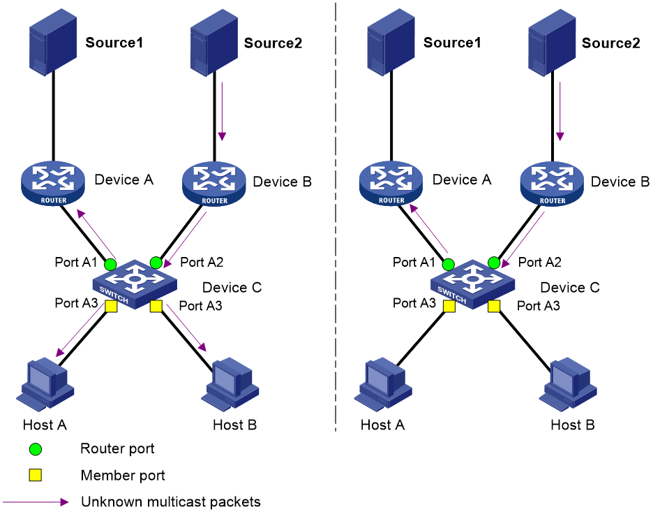
Q. Why cannot an IGMP snooping-enabled Layer 2 device process IGMPv3 reports?
You must specify IGMP snooping version 3. The default IGMP snooping version is 2 when IGMP snooping is enabled. An IGMP snooping-enabled Layer 2 device floods IGMPv3 reports from a receiver host in the VLAN or VSI instead of processing them.
After you specify IGMP snooping version 3, the Layer 2 device can forward IGMPv3 reports through all the router ports in the VLAN or VSI. It also resolves the address of the reported multicast group, and looks up the forwarding table for a matching entry as follows:
· If no match is found, the Layer 2 device creates a forwarding entry with the receiving port as an outgoing interface. It also marks the receiving port as a dynamic member port and starts an aging timer for the port.
· If a match is found but the matching forwarding entry does not contain the receiving port, the Layer 2 device adds the receiving port to the outgoing interface list. It also marks the receiving port as a dynamic member port and starts an aging timer for the port.
· If a match is found and the matching forwarding entry contains the receiving port, the Layer 2 device restarts the aging timer for the port.
Q. What is the purpose of an IGMP snooping querier? Can more than one IGMP snooping querier be configured?
This feature enables the Layer 2 device to periodically send IGMP general queries to establish and maintain multicast forwarding entries at the data link Layer. You can configure an IGMP snooping querier on a network without Layer 3 multicast devices.
To avoid traffic interruption caused by the failure of a single querier in a VLAN or VSI, you can configure multiple queriers in the VLAN or VSI. However, to reduce queries in the network and to prevent receivers from receiving too many copies of the same data packets, you must enable querier election. When the elected querier fails, the device starts a new querier election to ensure multicast forwarding.
Q. Layer 3 multicast traffic cannot be forwarded in a PIM domain after Layer 3 multicast functions are configured. Why does this happen?
The following are common reasons:
1. Unicast routes are unreachable.
2. IP multicast routing is not enabled.
3. PIM and IGMP are not configured correctly.
4. In a PIM-SM domain or BIDIR-PIM domain, no RP is configured or the configured RP information is incorrect.
5. Multicast forwarding boundaries are configured on the interface that forwards multicast data.
6. In a PIM-SM domain or BIDIR-PIM domain, an incorrect multicast source policy is configured.
7. Multicast forwarding entries are not generated.
To resolve the issue:
1. Use the ping command to test the connectivity between the multicast source and multicast receivers. If the ping fails, use the display ip routing-table command to check whether routes to the multicast source and multicast receivers exist. If not, check whether unicasts routes are configured correctly. If yes, go to step 2.
2. Use the display this command in system view to verify that IP multicast routing is enabled on each Layer 3 multicast device. By default, IP multicast routing is disabled.
3. Use the display this command in interface view on each device to verify that PIM or IGMP is configured correctly on the interface. PIM must be enabled on all interfaces except those connecting to multicast receivers. IGMP must be enabled on interfaces connecting to multicast receivers.
4. (For only a PIM-SM domain or BIDIR-PIM domain.) Use the display pim rp-info command to verify that the RP information is configured correctly. A multicast group can have only one RP, and the RP must be in the same PIM domain on each device.
5. Use the display this command in interface view on each device to verify that no multicast forwarding boundary on the interface that forwards multicast data. You can use the undo multicast boundary command to delete a multicast forwarding boundary.
6. (For only a PIM-SM domain or BIDIR-PIM domain.) Use the display this command in PIM view to check whether a multicast source policy is configured. If a multicast source policy is configured and it is incorrect, modify or delete it. If no multicast source policy is configured, go to step 7.
7. Check whether multicast forwarding entries exist:
a. Use the display pim routing-table command to check whether PIM routing entries exist. (*, G) entries and (S, G) entries should exist on a device connecting to multicast receivers, and (S, G) entries should exist on a device not connecting to multicast receivers.
b. Use the display multicast routing-table and display multicast fast-forwarding cache command to check whether multicast forwarding entries and multicast fast forwarding entries exist.
8. If all the entries exist, collect the entry information and contact H3C Support.
If no entries exist, also contact H3C Support.
Security
Q. Why don't the password control settings take effect?
The global password control feature is not enabled. To make a specific password control feature take effect, you must first enable the global password control feature.
1. Enter system view.
system-view
2. Enable global password control.
password-control enable
Q. When the device acts as an SSH server, why can't I log into the device after NTP is configured?
Identify whether password control is enabled on the device. Password control applies more restrictions on the login password. When password control is enabled, passwords have an aging time. The NTP settings changed the system time, and your password aged as a result. In this case, you can log in to the device through the console port and then disable the password control feature.
1. Enter system view.
system-view
2. Disable the password control feature.
undo password-control enable
After the system time is changed, you can also enable password control again as needed. For more information about password control, see Security Configuration Guide of the device.
Q. Why can't I change the password of the device?
Identify whether password control is enabled on the device. If password control is enabled, a password cannot be changed within the minimum update interval. The device typically prompts “Cannot change password until the update-wait time expires.” In this case, you can wait for the password update interval to expire or use the password-control update-interval interval command to adjust the minimum password update interval.
Q. When the device acts as an SSH server, in what situation does the device need to modify the authentication timeout time?
By default, the SSH user authentication timeout is 60 seconds.
After establishing a TCP connection, an illegal SSH user might not perform authentication but occupy the process to affect normal logins of legitimate users. In this case, you can set an authentication timeout time. If a user cannot finish authentication within the timeout time, the device denies the user connection.
An improper short authentication timeout time might cause legitimate SSH users unable to log in. The device prompts Authentication timed out for x.x.x.x (IP address of the user). In this case, you can use the ssh server authentication-timeout command in system view to adjust the authentication timeout time.
Q. When the device acts as an SSH client, how can I delete a server public key from the local public key file?
You can delete the public key of the specified server from the public key file of the SSL client by using the delete ssh client server-public-key command.
When the device logs in to the SSH server as a client for the first time, a message of Do you want to save the server public key? will be displayed. You can enter Y to save the server public key to the local public key file of the device. If the SSH server re-generates a public key, the server's public key and that saved on the client will be inconsistent. Therefore, the SSH client cannot log in to the server any more. You are prompted a message of The server's host key does not match the local cached key…To resolve this issue, you can use the delete ssh client server-public-key command to delete the server public key saved on the client.
Q. When you enable the Stelnet server on the device, why cannot the client connect to the Stelnet server?
For a user on the Stelnet client to successfully log in to the server, you must configure a user line with the scheme authentication mode for the user.
1. Enter system view.
system-view
2. Enter VTY user line view.
line vty number [ ending-number ]
3. Set the login authentication mode to scheme.
authentication-mode scheme
By default, the authentication mode is password.
If no user line with the scheme authentication mode is configured, the client cannot connect to the server.
ACL and QoS
Q. Why cannot a traffic class containing multiple match criteria match any traffic?
Use the traffic classifier command to change the match logic from AND to OR.
If you configure multiple match criteria and specify the match logic as AND, a packet matches the traffic class only if it matches all the match criteria. If you specify the match logic as OR, a packet matches the traffic class as long as it matches one of the match criteria.
Q. Why cannot an ACL deny incoming packets from a network segment?
Check whether the reverse mask for the IP address is correct in the ACL rule.
You must enter a reverse mask instead of a mask after a source or destination IP address in an ACL rule.
For example, if you want to match IP addresses in the 192.168.1.0/24 segment, you must enter 192.168.1.0 0.0.0.255 in an ACL rule.
Q. Why doesn't an ACL applied to a VLAN interface for packet filtering take effect on Layer 2 packets?
You can use the following methods to resolve this issue:
· Remove the ACL from the VLAN interface, and apply it to the corresponding Layer 2 interface.
· Execute the packet-filter filter all command on the VLAN interface to filter all packets. By default, an ACL applied to a VLAN interface filters only Layer 3 packets.
Q. Why cannot packets matching an IPSG binding be forwarded?
Check whether an ACL is applied for packet filtering.
If an ACL is applied for packet filtering, specify the counting keyword for the applied ACL, and use the command to check whether the packets also match a deny rule in the ACL.
An ACL applied for packet filtering has higher priority over an IPSG binding. If a packet matches both an ACL with a deny rule and an IPSG binding, the packet is dropped.
Q. What is the ACL rule match order?
The rules in an ACL are sorted in a specific order. When a packet matches a rule, the device stops the match process and performs the action defined in the rule. If an ACL contains overlapping or conflicting rules, the matching result and action to take depend on the rule order.
The following ACL rule match orders are available:
· config—Sorts ACL rules in ascending order of rule ID. A rule with a lower ID is matched before a rule with a higher ID. If you use this method, check the rules and their order carefully.
|
|
NOTE: The match-order { auto | config } command can be used to configure the ACL rule match order. The default match order is config. The match order of user-defined ACLs can only be config. |
· auto—Sorts ACL rules in depth-first order. Depth-first ordering makes sure any subset of a rule is always matched before the rule. The following table lists the sequence of tie breakers that depth-first ordering uses to sort rules for each type of ACL.
Table 5 Sorting ACL rules in depth-first order
|
ACL type |
Sequence of tie breakers |
|
IPv4 basic ACL |
1. VPN instance. 2. More 0s in the source IPv4 address wildcard (more 0s means a narrower IPv4 address range). 3. Rule configured earlier. |
|
IPv4 advanced ACL |
1. VPN instance. 2. Specific protocol number. 3. More 0s in the source IPv4 address wildcard mask. 4. More 0s in the destination IPv4 address wildcard. 5. Narrower TCP/UDP service port number range. 6. Rule configured earlier. |
|
IPv6 basic ACL |
1. VPN instance. 2. Longer prefix for the source IPv6 address (a longer prefix means a narrower IPv6 address range). 3. Rule configured earlier. |
|
IPv6 advanced ACL |
1. VPN instance. 2. Specific protocol number. 3. Longer prefix for the source IPv6 address. 4. Longer prefix for the destination IPv6 address. 5. Narrower TCP/UDP service port number range. 6. Rule configured earlier. |
|
Layer 2 ACL |
1. More 1s in the source MAC address mask (more 1s means a smaller MAC address). 2. More 1s in the destination MAC address mask. 3. Rule configured earlier. |
A wildcard mask, also called an inverse mask, is a 32-bit binary number represented in dotted decimal notation. In contrast to a network mask, the 0 bits in a wildcard mask represent "do care" bits, and the 1 bits represent "don't care" bits. If the "do care" bits in an IP address are identical to the "do care" bits in an IP address criterion, the IP address matches the criterion. All "don't care" bits are ignored. The 0s and 1s in a wildcard mask can be noncontiguous. For example, 0.255.0.255 is a valid wildcard mask.
High availability
Q. Why does a VRRP group become invalid after I modify the VRRP version?
The version of VRRP on all devices in a VRRP group must be the same. In VRRPv2, all devices in a VRRP group must have the same interval for sending VRRP advertisements.
Execute the display vrrp verbose command on all devices in the VRRP group. In the command output, the Version field displays the current version of the VRRP group. If different versions are specified for the devices, execute the vrrp version command to ensure VRRP version consistency.
If all the devices use VRRPv2, execute the display vrrp verbose command. In the command output, the Adver Timer field displays the VRRP advertisement sending interval. If different values are displayed for the devices, execute the vrrp vrid timer advertise command to ensure consistency of the VRRP advertisement sending intervals.
Q. No master/backup switchover occurs in a VRRP group when the uplink of the master device goes down. Why does this happen?
VRRP uses Track to detect link status, because it does not provide the link state detection capabilities. Execute the display vrrp verbose command on the master device in the VRRP group. In the VRRP Track Information field of the command output, you can see whether a track entry is associated with the device. If no track entry is associated, execute the vrrp vrid track command to configure collaboration between VRRP, Track, and NQA (or BFD) on the master device. This configuration enables the master device to monitor the uplink status.
Q. A track entry is associated with VRRP to monitor the uplink status of the master device. If the track entry becomes Negative, no master/backup switchover occurs in the VRRP group. Why does this happen?
To enable the VRRP group to perform master/backup switchover when the track entry state becomes Negative, make sure the priority of the master device is reduced to a specific value to trigger a switchover.
Execute the display vrrp verbose command on the master device. In the VRRP Track Information field of the command output, verify that the Pri Reduced field is displayed. If the Weight Reduced field is displayed, execute the vrrp vrid track command to configure the priority reduced setting.
If the Pri Reduced field is displayed, verify that the running priority (Running Pri) of the master device is smaller than the other devices in the VRRP group. If not, use the vrrp vrid track command to set a larger value for the priority reduced keyword. This ensures that the priority of master device can decrease to a value smaller that the priority of other devices.
Q. For the IE switch series that supports the DIP switch, after I configure RRPP settings and save the configuration, the RRPP configuration is lost upon a device reboot. Why does this happen?
Certain IE switch series support manual RRPP configuration and DIP switch-based RRPP configuration.
If the RRPP DIP switch is ON, the device automatically configures the following RRPP settings:
1. Creates RRPP domain 1.
2. Configures VLAN 4092 as the primary control VLAN and VLAN 4093 as the secondary control VLAN.
3. Configures the VLANs mapped to MSTP instance 0 as the protected VLANs.
4. Configures RRPP ports and RRPP nodes.
The device configures itself as a transit node and specifies the lower-numbered port connected to the ring as the primary port and the other port as the secondary port.
5. Activates RRPP domain 1.
Upon startup, the device detects the DIP switch status. If the RRPP DIP switch is ON, the device automatically configures the previous RRPP settings. The settings in the configuration file might conflict with the settings configured through the DIP switch. For example, RRPP domain 2 and control VLAN 4093 exist in the configuration file, which conflict with the secondary control VLAN for RRPP domain 1 configured through the DIP switch. In this case, the configuration recovery will fail.
To avoid this issue, make sure no conflicting settings exist for the manually configuration and the DIP switch-based configuration if you want to use both configuration methods.
Network management and monitoring
This section contains the most frequently asked questions about network management and monitoring.
Q. A power interface (PI, also called a PoE port) fails to supply PoE to a PD. How do I resolve the issue?
A. Perform the following steps:
1. Ensure normal operation of the device and correct connection of the cables.
2. Verify that the PI is PoE enabled.
Execute the display poe interface command to view the PoE supply status of the PI. If the value of the PoE Status field is Disabled, the PI is not PoE enabled. Execute the poe enable command in PI view to enable PoE on the PI.
3. Verify that the PSE or PI is enabled with nonstandard PD detection.
PDs are classified into standard PDs and nonstandard PDs. Standard PDs are compliant with IEEE 802.3af and IEEE 802.3at. A PSE supplies power to a nonstandard PD only after nonstandard PD detection is enabled.
You can configure PSE-based or PI-based nonstandard PD detection.
¡ To enable PSE-based nonstandard PD detection, execute the poe legacy enable pse pse-id command in system view. This operation enables nonstandard PD detection for all PIs on the PSE.
¡ To enable nonstandard PD detection for a PI, execute the poe legacy enable command in PI view.
4. Verify that the PSE firmware is updated.
If the PSE firmware is not the most recent version, contact H3C Support to obtain the most recent PSE firmware version. Then execute the full filename [ pse pse-id ]command in system view to update the PSE firmware.
You can upgrade the PSE firmware online in the following modes:
¡ Refresh mode—Execute the poe update refresh filename [ pse pse-id ]command in system view. This mode updates the PSE firmware without deleting it. You can use the refresh mode in most cases.
¡ Full mode—Execute the poe update full filename [ pse pse-id ]command in system view. This mode deletes the current PSE firmware and reloads a new one. Use the full mode if the PSE firmware is damaged and you cannot execute any PoE commands.
As shown in this example, the firmware of PSE 4 is updated in refresh mode:
<Sysname> system-view
[Sysname] poe update refresh POE-168.bin pse 4
Q. What should I do if an NMS fails to monitor and manage a remote device?
A. Perform the following steps:
1. Verify that the NMS and agent run the same SNMP version.
Execute the display snmp-agent sys-info command on the device to view the SNMP version of the device. If the agent runs a different SNMP version than the NMS, execute the snmp-agent sys-info version command in system view to specify an SNMP version consistent with that of the NMS for the device.
A device supports SNMPv1, SNMPv2c, and SNMPv3 when operating in non-FIPS mode and supports only SNMPv3 when operating in FIPS mode.
2. Verify that the NMS and agent use the same community name.
Execute the display snmp-agent community command to view the SNMPv1 or SNMPv2c community name. If the NMS and agent use different community names, use either of the following methods to configure the same community name for them.
¡ Configure an SNMPv1 or SNMPv2c community directly:
- In VACM mode, execute the snmp-agent community { read | write } [ simple | cipher ] community-name [ mib-view view-name ] [ acl { ipv4-acl-number | name ipv4-acl-name } | acl ipv6 { ipv6-acl-number | name ipv6-acl-name } ] * command in system view.
- In RBAC mode, execute the snmp-agent community [ simple | cipher ] community-name user-role role-name [ acl { ipv4-acl-number | name ipv4-acl-name } | acl ipv6 { ipv6-acl-number | name ipv6-acl-name } ] * command in system view.
¡ Configure an SNMPv1 or SNMPv2c community by creating an SNMPv1 or SNMPv2c user. The username will be used as the community name.
# Create an SNMPv1/v2c group by executing the snmp-agent group { v1 | v2c } group-name [ notify-view view-name | read-view view-name | write-view view-name ] * [ acl { ipv4-acl-number | name ipv4-acl-name } | acl ipv6 { ipv6-acl-number | name ipv6-acl-name } ] command in system view.
# Create and add an SNMPv1/v2c user to the group by executing the snmp-agent usm-user { v1 | v2c } user-name group-name [ acl { ipv4-acl-number | name ipv4-acl-name } | acl ipv6 { ipv6-acl-number | name ipv6-acl-name } ] command in system view.
Q. Will setting the local clock as a reference clock affect NTP time synchronization accuracy?
A. Yes.
Typically, an NTP network uses an authoritative clock (such as an atomic clock) as the primary time server to synchronize the clocks of the devices on the network.
In some special networks, such as an isolated network that cannot communicate with the outside world, devices cannot synchronize time with an authoritative clock. You can select a device with a more accurate clock from the network, and execute the ntp-service refclock-master [ ip-address ] [ stratum ] command in system view to specify the device to synchronize time with the local clock. Then configure other devices to synchronize time with this device.
This configuration might reduce NTP time synchronization accuracy and cause time errors of devices on the network. Be cautious before using the configuration.
Q. Must the clock stratum of the NTP server be smaller than that of the NTP client?
A. Yes. If the clock stratum of the NTP server is larger than or equal to that of the NTP client, the client will not synchronize time with the server.
Q. Why is the NTP client not synchronized with the NTP server, with a time difference of several hours from the NTP server?
A. The reasons that cause the issue include:
· The NTP client synchronizes the UTC time from the NTP server.
· The NTP client is different than the NTP server in daylight saving time and time zone settings.
To resolve the issue, execute the clock timezone and clock summer-time commands on the NTP client to ensure that the NTP client has the same daylight saving time and time zone settings as the NTP server.
Q. In what conditions can I configure PTP port roles manually? What are the restrictions?
A. As a best practice, use BMC for automatic negotiation of PTP port roles.
You can configure PTP port roles manually when the following conditions are present:
· A few PTP ports exist in the network.
· BMC automatic negotiation of PTP port roles fail. As a result, multiple PTP ports in the network are in Master role.
To identify whether multiple PTP ports in Master role, execute the display ptp interface brief command. If multiple PTP ports are in Master role, execute the ptp force-state command in interface view to change the PTP port role forcibly. Ensure that only one PTP port is in Master role.
By default, the PTP port roles are automatically negotiated based on the BMC algorithm. If you use the ptp force-state command to change the role of one PTP port, all the other PTP ports in the PTP domain stop working. For these PTP ports to function, you must specify a role for each of them by using this command. As a best practice, enable automatic negotiation of PTP port roles based on the BMC algorithm.
Q. I cannot remotely manage a device from Cloudnet. How do I resolve the issue?
A. Determine whether the device supports remote management from Cloudnet. If the device supports remote management from Cloudnet but fails to be managed from Cloudnet, perform the following steps:
1. Execute the display current-configuration command to verify that the device is configured with the Cloudnet server domain name.
If it is not configured with the domain name, execute the cloud-management server domain oasis.h3c.com command to specify the Cloudnet server domain name for the device.
2. Configure DNS correctly to resolve the Cloudnet server domain name to a correct IP address.
3. Add the serial number of the device to the Cloudnet server. To obtain the serial number of the device, execute the display device manuinfo command.
For more information, see cloud connection configuration in the network management and configuration guide for the device.
Q. The device generates a large volume of logs. How do I resolve the issue?
A. The information center on the device receives logs generated by service modules and outputs logs to different destinations according to log output rules. Based on the logs, you can monitor device performance and troubleshoot network problems. However, a large volume of logs generated during a short period of time might cause high CPU usage of the INFO process. To resolve this issue, perform the following steps:
1. View generated logs to verify that no exceptions causing excessive log generation exist.
For example, if a lot of link up or link down log messages are generated for an interface, it indicates that the interface state is unstable. Resolve the issues that caused the unstable state of the interface, so that no such logs will be generated.
2. Modify the log output rule to allow sending only necessary logs to a specific destination.
For example, you can allow the VLAN module to output only the logs with severity level of notification and higher levels to the console by using the info-center source vlan console level notification command.
3. Disable log output of the specified modules to a destination.
If you do not need the logs of a module, you can disable sending the module's logs to a specific destination. For example, use the info-center source portal monitor deny command to disable log output of the portal module to the monitor terminal.
VXLAN
Q. I failed to configure VXLAN commands on the device. What should I do?
A. Perform the following steps:
1. Verify that the device supports VXLAN.
2. Determine whether the device is required to operate in a specific system operating mode. If yes, execute the display switch-mode status or display system-working-mode command to verify that the device is operating in a VXLAN-capable mode. The command used to display system operating mode information varies by device model and software version. For more information, see device management in Fundamentals Configuration Guide for the device and software version.
3. If the device is not operating in a VXLAN-capable mode, execute the switch-mode or system-working-mode command to configure the device to operate in a VXLAN-capable mode. Then, save the configuration and restart the device. The command used to change the system operating mode varies by device model and software version. For more information, see device management in Fundamentals Configuration Guide for the device and software version.
4. Determine whether the failed commands must be executed in a specific hardware resource mode. If yes, execute the display hardware-resource vxlan command to obtain the VXLAN hardware resource mode.
5. If the device is not operating in a hardware resource mode that supports these commands, execute the hardware-resource vxlan command to change the VXLAN hardware resource mode if necessary. Then, save the configuration and restart the device.
For more information about VXLAN configuration, see VXLAN Configuration Guide for the device.
