- Table of Contents
-
- 02-Configuration Examples
- 01-H3C_AAA_Configuration_Examples
- 02-H3C_ACL_Configuration_Examples
- 03-H3C_ATM_Configuration_Examples
- 04-H3C_IGMP_Configuration_Examples
- 05-H3C_IP_Source_Guard_Configuration_Examples
- 06-H3C_Ethernet_OAM_Configuration_Examples
- 07-H3C_NQA_Configuration_Examples
- 08-H3C_QinQ_Configuration_Examples
- 09-H3C_OSPF_Configuration_Examples
- 10-H3C_MPLS_TE_Configuration_Examples
- 11-H3C_OpenFlow_Configuration_Examples
- 12-H3C_NAT_Configuration_Examples
- 13-H3C_RBAC_Configuration_Examples
- 14-H3C_IRF_Configuration_Examples
- 15-H3C_POS_Interface_Configuration_Examples
- 16-H3C_CPOS_Interface_Configuration_Examples
- 17-H3C_DHCP_Relay_Redundancy_Configuration_Examples
- 18-H3C_DLDP_Configuration_Examples
- 19-H3C_IS-IS_Configuration_Examples
- 20-H3C_MPLS_L3VPN_Configuration_Examples
- 21-H3C_SSH_Configuration_Examples
- 22-H3C_Login_Management_Configuration_Examples
- 23-H3C_SNMP_Configuration_Examples
- 24-H3C_Priority_Marking_and_Queue_Scheduling_Configuration_Examples
- 25-H3C_Multicast_VPN_Configuration_Examples
- 26-H3C_BGP_Configuration_Examples
- 27-H3C_HoVPN_Configuration_Examples
- 28-H3C_L2TP_Configuration_Examples
- 29-H3C_VRRP_Configuration_Examples
- 30-H3C_Traffic_Filtering_Configuration_Examples
- 31-H3C_Samplers_and_IPv4_NetStream_Configuration_Examples
- 32-H3C_Software_Upgrade_Examples
- 33-H3C_MPLS_L2VPN_Configuration_Examples
- 34-H3C_NetStream_Configuration_Examples
- 35-H3C_Policy-Based_Routing_Configuration_Examples
- 36-H3C_Traffic_Policing_Configuration_Examples
- 37-H3C_BFD_Configuration_Examples
- 38-H3C_OSPFv3_Configuration_Examples
- 39-H3C_VPLS_Configuration_Examples
- 40-H3C_GTS_and_Rate_Limiting_Configuration_Examples
- 41-H3C_IPv6_IS-IS_Configuration_Examples
- 42-H3C_MPLS OAM_Configuration_Examples
- 43-H3C_BGP_Route_Selection_Configuration_Examples
- 44-H3C_IS-IS_Route_Summarization_Configuration_Examples
- 45-H3C_SRv6 Configuration Examples
- 46-H3C_Attack_Protection_Configuration_Examples
- 47-H3C_OSPF_Multi-Process_Configuration_Examples
- 48-H3C_OSPF_with_Multi-Instance_Configuration_Examples
- 49-H3C_ARP_Attack_Protection_Configuration_Examples
- 50-H3C_DHCPv6_Server_and_DHCPv6_Prefix_Client_Configuration_Examples
- 51-CE1 Interface Connection Configuration Examples
- 52-GRE Tunnel Establishment Using OSPF Configuration Examples
- 53-GRE Tunnel Establishment Using Static Routes Configuration Examples
- 54-OSPF over IPsec for Overseas Branch Access Configuration Examples
- 55-General QoS Configuration Examples
- 56-QoS Configuration Examples for the Financial Industry
- Related Documents
-
| Title | Size | Download |
|---|---|---|
| 48-H3C_OSPF_with_Multi-Instance_Configuration_Examples | 239.17 KB |
Example: Configuring the OSPF multi-instance feature
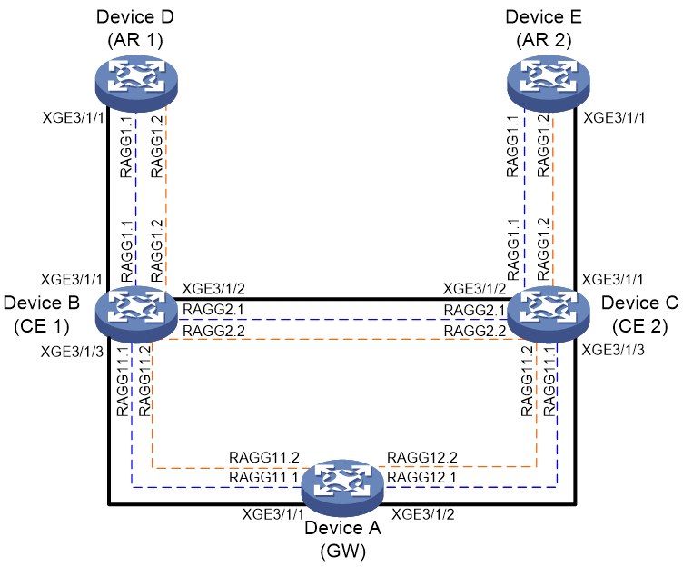
Network configuration
Configure multiple OSPF instances between the access devices and the core network to isolate the routes of different services.
As shown in Figure 1, the roles of devices are as follows:
· Device A is a gateway device, referred to as GW.
· Device B and Device C are core network devices, referred to as CEs.
· Device D and Device E are access devices, referred to as ARs.
In this example, service 1 uses VPN instance vpn1, and service 2 uses VPN instance vpn2. To isolate the routes for service 1 from those for service 2 through the OSPF multi-instance feature, perform the following tasks:
· Create VPN instances vpn1 and vpn2 on GW.
· Create OSPF processes OSPF 15 and OSPF 115 on GW. Associate OSPF 15 with vpn1 and OSPF 115 with vpn2.
· Create VPN instances vpn1 and vpn2 on CEs and ARs.
· Create OSPF processes OSPF 15 and OSPF 115 on CEs and ARs. Associate OSPF 15 with vpn1 and OSPF 115 with vpn2.
· Enable the CEs to perform the following tasks:
a. Summarize the routes of different services as static black hole routes.
b. Redistribute the summary static black hole routes into OSPF.
c. Use routing policies to control route redistribution.
This prevents the CEs from advertising the individual routes to ARs, thus reducing the number of routes on ARs and reducing the risk of route flapping.
The service networks on CE 1 and CE 2 (in this example, loopback addresses are used as service networks) are as follows:
¡ On CE 1, the service network for vpn1 is 19.0.0.0/24 and the service network for vpn2 is 20.0.0.0/24.
¡ On CE 2, the service network for vpn1 is 21.0.0.0/24 and the service network for vpn2 is 22.0.0.0/24.
|
Device |
Interface |
IP address |
VPN instance |
|
Device A |
Route-Aggregation 11.1 |
201.1.1.2/24 |
vpn1 |
|
|
Route-Aggregation 11.2 |
202.1.1.2/24 |
vpn2 |
|
|
Route-Aggregation 12.1 |
203.1.1.2/24 |
vpn1 |
|
|
Route-Aggregation 12.2 |
204.1.1.2/24 |
vpn2 |
|
|
LoopBack 1 |
1.1.1.9/32 |
vpn1 |
|
|
LoopBack 2 |
1.1.1.10/32 |
vpn2 |
|
Device B |
Route-Aggregation 1.1 |
11.1.1.2/24 |
vpn1 |
|
|
Route-Aggregation 1.2 |
12.1.1.2/24 |
vpn2 |
|
|
Route-Aggregation 2.1 |
172.168.1.1/24 |
vpn1 |
|
|
Route-Aggregation 2.2 |
192.168.1.1/24 |
vpn2 |
|
|
Route-Aggregation 11.1 |
201.1.1.1/24 |
vpn1 |
|
|
Route-Aggregation 11.2 |
202.1.1.1/24 |
vpn2 |
|
|
LoopBack 1 |
2.2.2.9/32 |
vpn1 |
|
|
LoopBack 2 |
2.2.2.10/32 |
vpn2 |
|
|
LoopBack 101 |
19.0.0.1/29 |
vpn1 |
|
|
LoopBack 102 |
20.0.0.1/29 |
vpn2 |
|
|
LoopBack 103 |
19.0.0.9/29 |
vpn1 |
|
|
LoopBack 104 |
20.0.0.9/29 |
vpn2 |
|
|
LoopBack 105 |
19.0.0.17/28 |
vpn1 |
|
|
LoopBack 106 |
20.0.0.17/28 |
vpn2 |
|
|
LoopBack 107 |
19.0.0.33/28 |
vpn1 |
|
|
LoopBack 108 |
20.0.0.33/28 |
vpn2 |
|
Device C |
Route-Aggregation 1.1 |
13.1.1.2/24 |
vpn1 |
|
|
Route-Aggregation 1.2 |
14.1.1.3/24 |
vpn2 |
|
|
Route-Aggregation 2.1 |
172.168.1.2/24 |
vpn1 |
|
|
Route-Aggregation 2.2 |
192.168.1.2/24 |
vpn2 |
|
|
Route-Aggregation 11.1 |
203.1.1.1/24 |
vpn1 |
|
|
Route-Aggregation 11.2 |
204.1.1.1/24 |
vpn2 |
|
|
LoopBack 1 |
3.3.3.9/32 |
vpn1 |
|
|
LoopBack 2 |
3.3.3.10/32 |
vpn2 |
|
|
LoopBack 101 |
21.0.0.1/29 |
vpn1 |
|
|
LoopBack 102 |
22.0.0.1/29 |
vpn2 |
|
|
LoopBack 103 |
21.0.0.9/29 |
vpn1 |
|
|
LoopBack 104 |
22.0.0.9/29 |
vpn2 |
|
|
LoopBack 105 |
21.0.0.17/28 |
vpn1 |
|
|
LoopBack 106 |
22.0.0.17/28 |
vpn2 |
|
|
LoopBack 107 |
21.0.0.33/28 |
vpn1 |
|
|
LoopBack 108 |
22.0.0.33/28 |
vpn2 |
|
Device D |
Route-Aggregation 1.1 |
11.1.1.1/24 |
vpn1 |
|
|
Route-Aggregation 1.2 |
12.1.1.1/24 |
vpn2 |
|
|
LoopBack 1 |
4.4.4.9/32 |
vpn1 |
|
|
LoopBack 2 |
4.4.4.10/32 |
vpn2 |
|
Device E |
Route-Aggregation 1.1 |
13.1.1.1/24 |
vpn1 |
|
|
Route-Aggregation 1.2 |
14.1.1.1/24 |
vpn2 |
|
|
LoopBack 1 |
5.5.5.9/32 |
vpn1 |
|
|
LoopBack 2 |
5.5.5.10/32 |
vpn2 |
Procedures
Configuring Device A
# Specify DeviceA as the device name.
<Sysname> system-view
[Sysname] sysname DeviceA
# Create VPN instances vpn1 and vpn2.
[DeviceA] ip vpn-instance vpn1
[DeviceA-vpn-instance-vpn1] quit
[DeviceA] ip vpn-instance vpn2
[DeviceA-vpn-instance-vpn2] quit
# Create Layer 3 aggregate interface 11 on Device A. This interface connects Device A to Device B.
[DeviceA] interface route-aggregation 11
[DeviceA-Route-Aggregation11] link-aggregation mode dynamic
[DeviceA-Route-Aggregation11] quit
# Assign Ten-GigabitEthernet 3/1/1 to aggregation group 11.
[DeviceA] interface ten-gigabitethernet 3/1/1
[DeviceA-Ten-GigabitEthernet3/1/1] port link-mode route
[DeviceA-Ten-GigabitEthernet3/1/1] port link-aggregation group 11
[DeviceA-Ten-GigabitEthernet3/1/1] quit
# Create Layer 3 aggregate subinterface 11.1 and associate it with vpn1. Configure the subinterface to terminate VLAN-tagged packets with outermost VLAN ID 10. Assign 201.1.1.2/24 to the subinterface.
[DeviceA] interface route-aggregation 11.1
[DeviceA-Route-Aggregation11.1] ip binding vpn-instance vpn1
[DeviceA-Route-Aggregation11.1] vlan-type dot1q vid 10
[DeviceA-Route-Aggregation11.1] ip address 201.1.1.2 255.255.255.0
# On subinterface 11.1, set the hello interval to 1 second, the dead interval to 4 seconds, and the OSPF cost to 10, and enable MD5 authentication.
[DeviceA-Route-Aggregation11.1] ospf timer hello 1
[DeviceA-Route-Aggregation11.1] ospf timer dead 4
[DeviceA-Route-Aggregation11.1] ospf cost 10
[DeviceA-Route-Aggregation11.1] ospf authentication-mode md5 1 plain 12345
[DeviceA-Route-Aggregation11.1] quit
# Create Layer 3 aggregate subinterface 11.2 and associate it with vpn2. Configure the subinterface to terminate VLAN-tagged packets with outermost VLAN ID 20. Assign 202.1.1.2/24 to the subinterface.
[DeviceA] interface route-aggregation 11.2
[DeviceA-Route-Aggregation11.2] ip binding vpn-instance vpn2
[DeviceA-Route-Aggregation11.2] vlan-type dot1q vid 20
[DeviceA-Route-Aggregation11.2] ip address 202.1.1.2 255.255.255.0
# On subinterface 11.2, set the hello interval to 1 second, the dead interval to 4 seconds, and the OSPF cost to 10, and enable MD5 authentication.
[DeviceA-Route-Aggregation11.2] ospf timer hello 1
[DeviceA-Route-Aggregation11.2] ospf timer dead 4
[DeviceA-Route-Aggregation11.2] ospf cost 10
[DeviceA-Route-Aggregation11.2] ospf authentication-mode md5 1 plain 12345
[DeviceA-Route-Aggregation11.2] quit
# Create Layer 3 aggregate interface 12 on Device A. This interface connects Device A to Device C.
[DeviceA] interface route-aggregation 12
[DeviceA-Route-Aggregation12] link-aggregation mode dynamic
[DeviceA-Route-Aggregation12] quit
# Assign Ten-GigabitEthernet 3/1/2 to aggregation group 12.
[DeviceA] interface ten-gigabitethernet 3/1/2
[DeviceA-Ten-GigabitEthernet3/1/2] port link-mode route
[DeviceA-Ten-GigabitEthernet3/1/2] port link-aggregation group 12
[DeviceA-Ten-GigabitEthernet3/1/2] quit
# Create Layer 3 aggregate subinterface 12.1 and associate it with vpn1. Configure the subinterface to terminate VLAN-tagged packets with outermost VLAN ID 10. Assign 203.1.1.2/24 to the subinterface.
[DeviceA] interface route-aggregation 12.1
[DeviceA-Route-Aggregation12.1] ip binding vpn-instance vpn1
[DeviceA-Route-Aggregation12.1] vlan-type dot1q vid 10
[DeviceA-Route-Aggregation12.1] ip address 203.1.1.2 255.255.255.0
# On subinterface 12.1, set the hello interval to 1 second, the dead interval to 4 seconds, and the OSPF cost to 10, and enable MD5 authentication.
[DeviceA-Route-Aggregation12.1] ospf timer hello 1
[DeviceA-Route-Aggregation12.1] ospf timer dead 4
[DeviceA-Route-Aggregation12.1] ospf cost 10
[DeviceA-Route-Aggregation12.1] ospf authentication-mode md5 1 plain 12345
[DeviceA-Route-Aggregation12.1] quit
# Create Layer 3 aggregate subinterface 12.2 and associate it with vpn2. Configure the subinterface to terminate VLAN-tagged packets with outermost VLAN ID 20. Assign 202.1.1.2/24 to the subinterface.
[DeviceA] interface route-aggregation 12.2
[DeviceA-Route-Aggregation12.2] ip binding vpn-instance vpn2
[DeviceA-Route-Aggregation12.2] vlan-type dot1q vid 20
[DeviceA-Route-Aggregation12.2] ip address 204.1.1.2 255.255.255.0
# On subinterface 12.2, set the hello interval to 1 second, the dead interval to 4 seconds, and the OSPF cost to 10, and enable MD5 authentication.
[DeviceA-Route-Aggregation12.2] ospf timer hello 1
[DeviceA-Route-Aggregation12.2] ospf timer dead 4
[DeviceA-Route-Aggregation12.2] ospf cost 10
[DeviceA-Route-Aggregation12.2] ospf authentication-mode md5 1 plain 12345
[DeviceA-Route-Aggregation12.2] quit
# Assign 1.1.1.9/32 to loopback interface loopback 1. This IP address will be used as the router ID of OSPF process 15.
[DeviceA] interface loopback 1
[DeviceA-LoopBack1] ip binding vpn-instance vpn1
[DeviceA-LoopBack1] ip address 1.1.1.9 32
[DeviceA-LoopBack1] quit
# Assign 1.1.1.10/32 to loopback interface loopback 2. This IP address will be used as the router ID of OSPF process 115.
[DeviceB] interface loopback 2
[DeviceB-LoopBack2] ip binding vpn-instance vpn2
[DeviceB-LoopBack2] ip address 1.1.1.10 32
[DeviceB-LoopBack2] quit
# Create OSPF process 15, specify router ID 1.1.1.9 for it, and associate it with vpn1.
[DeviceA] ospf 15 router-id 1.1.1.9 vpn-instance vpn1
# Advertise service routes 201.1.1.0/24 and 203.1.1.0/24 for vpn1.
[DeviceA-ospf-15] area 0.0.0.0
[DeviceA-ospf-15-area-0.0.0.0] network 201.1.1.0 0.0.0.255
[DeviceA-ospf-15-area-0.0.0.0] network 203.1.1.0 0.0.0.255
[DeviceA-ospf-15-area-0.0.0.0] quit
[DeviceA-ospf-15] quit
# Create OSPF process 115, specify router ID 1.1.1.10 for it, and associate it with vpn2.
[DeviceA] ospf 115 router-id 1.1.1.10 vpn-instance vpn2
# Advertise service routes 202.1.1.0/24 and 204.1.1.0/24 for vpn2.
[DeviceA-ospf-115] area 0.0.0.0
[DeviceA-ospf-115-area-0.0.0.0] network 202.1.1.0 0.0.0.255
[DeviceA-ospf-115-area-0.0.0.0] network 204.1.1.0 0.0.0.255
[DeviceA-ospf-115-area-0.0.0.0] quit
[DeviceA-ospf-115] quit
Configuring Device B
# Specify DeviceB as the device name.
<Sysname> system-view
[Sysname] sysname DeviceB
# Create VPN instances vpn1 and vpn2.
[DeviceB] ip vpn-instance vpn1
[DeviceB-vpn-instance-vpn1] quit
[DeviceB] ip vpn-instance vpn2
[DeviceB-vpn-instance-vpn2] quit
# Associate loopback 101, loopback 103, loopback 105, and loopback 107 with vpn1 and assign IP addresses within network 19.0.0.0/24 to the loopback interfaces.
[DeviceB] interface loopback 101
[DeviceB-LoopBack101] ip binding vpn-instance vpn1
[DeviceB-LoopBack101] ip address 19.0.0.1 255.255.255.248
[DeviceB-LoopBack101] quit
[DeviceB] interface loopback 103
[DeviceB-LoopBack103] ip binding vpn-instance vpn1
[DeviceB-LoopBack103] ip address 19.0.0.9 255.255.255.248
[DeviceB-LoopBack103] quit
[DeviceB] interface loopback 105
[DeviceB-LoopBack105] ip binding vpn-instance vpn1
[DeviceB-LoopBack105] ip address 19.0.0.17 255.255.255.240
[DeviceB-LoopBack105] quit
[DeviceB] interface loopback 107
[DeviceB-LoopBack107] ip binding vpn-instance vpn1
[DeviceB-LoopBack107] ip address 19.0.0.33 255.255.255.240
[DeviceB-LoopBack107] quit
# Associate loopback 102, loopback 104, loopback 106, and loopback 108 with vpn2 and assign IP addresses within network 20.0.0.0/24 to the loopback interfaces.
[DeviceB] interface loopback 102
[DeviceB-LoopBack102] ip binding vpn-instance vpn2
[DeviceB-LoopBack102] ip address 20.0.0.1 255.255.255.248
[DeviceB-LoopBack102] quit
[DeviceB] interface loopback 104
[DeviceB-LoopBack104] ip binding vpn-instance vpn2
[DeviceB-LoopBack104] ip address 20.0.0.9 255.255.255.248
[DeviceB-LoopBack104] quit
[DeviceB] interface loopback 106
[DeviceB-LoopBack106] ip binding vpn-instance vpn2
[DeviceB-LoopBack106] ip address 20.0.0.17 255.255.255.240
[DeviceB-LoopBack106] quit
[DeviceB] interface loopback 108
[DeviceB-LoopBack108] ip binding vpn-instance vpn2
[DeviceB-LoopBack108] ip address 20.0.0.33 255.255.255.240
[DeviceB-LoopBack108] quit
# Create Layer 3 aggregate interface 1 on Device B. This interface connects Device B to Device D.
[DeviceB] interface route-aggregation 1
[DeviceB-Route-Aggregation1] link-aggregation mode dynamic
[DeviceB-Route-Aggregation1] quit
# Assign Ten-GigabitEthernet 3/1/1 to aggregation group 1.
[DeviceB] interface ten-gigabitethernet 3/1/1
[DeviceB-Ten-GigabitEthernet3/1/1] port link-mode route
[DeviceB-Ten-GigabitEthernet3/1/1] port link-aggregation group 1
[DeviceB-Ten-GigabitEthernet3/1/1] quit
# Create Layer 3 aggregate subinterface 1.1 and associate it with vpn1. Configure the subinterface to terminate VLAN-tagged packets with outermost VLAN ID 10. Assign 11.1.1.2/24 to the subinterface.
[DeviceB] interface route-aggregation 1.1
[DeviceB-Route-Aggregation1.1] ip binding vpn-instance vpn1
[DeviceB-Route-Aggregation1.1] vlan-type dot1q vid 10
[DeviceB-Route-Aggregation1.1] ip address 11.1.1.2 255.255.255.0
# On subinterface 1.1, set the hello interval to 1 second, the dead interval to 4 seconds, and the OSPF cost to 10, and enable MD5 authentication.
[DeviceB-Route-Aggregation1.1] ospf timer hello 1
[DeviceB-Route-Aggregation1.1] ospf timer dead 4
[DeviceB-Route-Aggregation1.1] ospf cost 10
[DeviceB-Route-Aggregation1.1] ospf authentication-mode md5 1 plain 12345
[DeviceB-Route-Aggregation1.1] quit
# Create Layer 3 aggregate subinterface 1.2 and associate it with vpn2. Configure the subinterface to terminate VLAN-tagged packets with outermost VLAN ID 20. Assign 12.1.1.2/24 to the subinterface.
[DeviceB] interface Route-Aggregation1.2
[DeviceB-Route-Aggregation1.1] ip binding vpn-instance vpn2
[DeviceB-Route-Aggregation1.1] vlan-type dot1q vid 20
[DeviceB-Route-Aggregation1.1] ip address 12.1.1.2 255.255.255.0
# On subinterface 1.2, set the hello interval to 1 second, the dead interval to 4 seconds, and the OSPF cost to 10, and enable MD5 authentication.
[DeviceB-Route-Aggregation1.1] ospf timer hello 1
[DeviceB-Route-Aggregation1.1] ospf timer dead 4
[DeviceB-Route-Aggregation1.1] ospf cost 10
[DeviceB-Route-Aggregation1.1] ospf authentication-mode md5 1 plain 12345
[DeviceB-Route-Aggregation1.1] quit
# Create Layer 3 aggregate interface 2 on Device B. This interface connects Device B to Device C.
[DeviceB] interface route-aggregation 2
[DeviceB-Route-Aggregation2] link-aggregation mode dynamic
[DeviceB-Route-Aggregation2] quit
# Assign Ten-GigabitEthernet 3/1/2 to aggregation group 2.
[DeviceB] interface ten-gigabitethernet 3/1/2
[DeviceB-Ten-GigabitEthernet3/1/2] port link-mode route
[DeviceB-Ten-GigabitEthernet3/1/2] port link-aggregation group 2
[DeviceB-Ten-GigabitEthernet3/1/2] quit
# Create Layer 3 aggregate subinterface 2.1 and associate it with vpn1. Configure the subinterface to terminate VLAN-tagged packets with outermost VLAN ID 10. Assign 172.168.1.1/24 to the subinterface.
[DeviceB] interface route-aggregation 2.1
[DeviceB-Route-Aggregation2.1] ip binding vpn-instance vpn1
[DeviceB-Route-Aggregation2.1] vlan-type dot1q vid 10
[DeviceB-Route-Aggregation2.1] ip address 172.168.1.1 255.255.255.0
# On subinterface 2.1, set the hello interval to 1 second, the dead interval to 4 seconds, and the OSPF cost to 10, and enable MD5 authentication.
[DeviceB-Route-Aggregation2.1] ospf timer hello 1
[DeviceB-Route-Aggregation2.1] ospf timer dead 4
[DeviceB-Route-Aggregation2.1] ospf cost 10
[DeviceB-Route-Aggregation2.1] ospf authentication-mode md5 1 plain 12345
[DeviceB-Route-Aggregation2.1] quit
# Create Layer 3 aggregate subinterface 2.2 and associate it with vpn2. Configure the subinterface to terminate VLAN-tagged packets with outermost VLAN ID 20. Assign 192.168.1.1/24 to the subinterface.
[DeviceB] interface route-aggregation 2.2
[DeviceB-Route-Aggregation2.2] ip binding vpn-instance vpn2
[DeviceB-Route-Aggregation2.2] vlan-type dot1q vid 20
[DeviceB-Route-Aggregation2.2] ip address 192.168.1.1 255.255.255.0
# On subinterface 2.2, set the hello interval to 1 second, the dead interval to 4 seconds, and the OSPF cost to 10, and enable MD5 authentication.
[DeviceB-Route-Aggregation2.2] ospf timer hello 1
[DeviceB-Route-Aggregation2.2] ospf timer dead 4
[DeviceB-Route-Aggregation2.2] ospf cost 10
[DeviceB-Route-Aggregation2.2] ospf authentication-mode md5 1 plain 12345
[DeviceB-Route-Aggregation2.2] quit
# Create aggregate interface 11 between Device B and Device A.
[DeviceB] interface route-aggregation 11
[DeviceB-Route-Aggregation11] link-aggregation mode dynamic
[DeviceB-Route-Aggregation11] quit
# Assign Ten-GigabitEthernet 3/1/3 to aggregation group 11.
[DeviceB] interface ten-gigabitethernet 3/1/3
[DeviceB-Ten-GigabitEthernet3/1/3] port link-mode route
[DeviceB-Ten-GigabitEthernet3/1/3] port link-aggregation group 11
[DeviceB-Ten-GigabitEthernet3/1/3] quit
# Create Layer 3 aggregate subinterface 11.1 and associate it with vpn1. Configure the subinterface to terminate VLAN-tagged packets with outermost VLAN ID 10. Assign 201.1.1.1/24 to the subinterface.
[DeviceB] interface route-aggregation 11.1
[DeviceB-Route-Aggregation11.1] ip binding vpn-instance vpn1
[DeviceB-Route-Aggregation11.1] vlan-type dot1q vid 10
[DeviceB-Route-Aggregation11.1] ip address 201.1.1.1 255.255.255.0
# On subinterface 11.1, set the hello interval to 1 second, the dead interval to 4 seconds, and the OSPF cost to 10, and enable MD5 authentication.
[DeviceB-Route-Aggregation11.1] ospf timer hello 1
[DeviceB-Route-Aggregation11.1] ospf timer dead 4
[DeviceB-Route-Aggregation11.1] ospf cost 10
[DeviceB-Route-Aggregation11.1] ospf authentication-mode md5 1 plain 12345
[DeviceB-Route-Aggregation11.1] quit
# Create Layer 3 aggregate subinterface 11.2 and associate it with vpn2. Configure the subinterface to terminate VLAN-tagged packets with outermost VLAN ID 20. Assign 202.1.1.1/24 to the subinterface.
[DeviceB] interface route-aggregation 11.2
[DeviceB-Route-Aggregation11.2] ip binding vpn-instance vpn2
[DeviceB-Route-Aggregation11.2] vlan-type dot1q vid 20
[DeviceB-Route-Aggregation11.2] ip address 202.1.1.1 255.255.255.0
# On Layer 3 aggregate subinterface 11.2, set the hello interval to 1 second, the dead interval to 4 seconds, and the OSPF cost to 10, and enable MD5 authentication.
[DeviceB-Route-Aggregation11.2] ospf timer hello 1
[DeviceB-Route-Aggregation11.2] ospf timer dead 4
[DeviceB-Route-Aggregation11.2] ospf cost 10
[DeviceB-Route-Aggregation11.2] ospf authentication-mode md5 1 plain 12345
[DeviceB-Route-Aggregation11.2] quit
# Configure IP prefix list list1 to permit routes destined for network 201.1.1.0/24 and 19.0.0.0/24.
[DeviceB] ip prefix-list list1 index 10 permit 201.1.1.0 24
[DeviceB] ip prefix-list list1 index 20 permit 19.0.0.0 24
# Configure IP prefix list list2 to permit routes destined for network 202.1.1.0/24 and 20.0.0.0/24.
[DeviceB] ip prefix-list list2 index 10 permit 202.1.1.0 24
[DeviceB] ip prefix-list list2 index 20 permit 20.0.0.0 24
# Create routing policy p1.
[DeviceB] route-policy p1 permit node 10
[DeviceB-route-policy-p1-10] if-match ip address prefix-list list1
[DeviceB-route-policy-p1-10] quit
# Create routing policy p2.
[DeviceB] route-policy p2 permit node 10
[DeviceB-route-policy-p2-10] if-match ip address prefix-list list2
[DeviceB-route-policy-p2-10] quit
# Configure a static summary route for the black hole routes of vpn1.
[DeviceB] ip route-static vpn-instance vpn1 19.0.0.0 24 null0
# Configure a static summary route for the black hole routes of vpn2.
[DeviceB] ip route-static vpn-instance vpn2 20.0.0.0 24 null0
# Assign 2.2.2.9/32 to loopback interface loopback 1. This IP address will be used as the router ID of OSPF process 15.
[DeviceB] interface loopback 1
[DeviceB-LoopBack1] ip binding vpn-instance vpn1
[DeviceB-LoopBack1] ip address 2.2.2.9 32
[DeviceB-LoopBack1] quit
# Assign 2.2.2.10/32 to loopback interface loopback 2. This IP address will be used as the router ID of OSPF process 115.
[DeviceB] interface loopback 2
[DeviceB-LoopBack2] ip binding vpn-instance vpn2
[DeviceB-LoopBack2] ip address 2.2.2.10 32
[DeviceB-LoopBack2] quit
# Create OSPF process 15, specify router ID 2.2.2.9 for it, and associate it with vpn1.
[DeviceB] ospf 15 router-id 2.2.2.9 vpn-instance vpn1
# In OSPF process 15, advertise service routes 11.1.1.0/24, 172.168.1.0/24, and 201.1.1.0/24 for vpn1.
[DeviceB-ospf-15] area 0.0.0.0
[DeviceB-ospf-15-area-0.0.0.0] network 11.1.1.0 0.0.0.255
[DeviceB-ospf-15-area-0.0.0.0] network 172.168.1.0 0.0.0.255
[DeviceB-ospf-15-area-0.0.0.0] network 201.1.1.0 0.0.0.255
[DeviceB-ospf-15-area-0.0.0.0] quit
# In OSPF process 15, redistribute direct routes and static summary service routes, and use routing policies to control route redistribution and prevent Device B from advertising detailed routes of service 1 to Device D.
[DeviceB-ospf-15] import-route direct route-policy p1
[DeviceB-ospf-15] import-route static route-policy p1
[DeviceB-ospf-15] quit
# Create OSPF process 15, specify router ID 2.2.2.9 for it, it and associate with vpn1.
[DeviceB] ospf 115 router-id 2.2.2.10 vpn-instance vpn2
# In OSPF process 115, advertise service routes 12.1.1.0/24, 192.168.1.0/24, and 201.1.1.0/24 for vpn2.
[DeviceB-ospf-115] area 0.0.0.0
[DeviceB-ospf-115-area-0.0.0.0] network 12.1.1.0 0.0.0.255
[DeviceB-ospf-115-area-0.0.0.0] network 192.168.1.0 0.0.0.255
[DeviceB-ospf-115-area-0.0.0.0] network 202.1.1.0 0.0.0.255
[DeviceB-ospf-115-area-0.0.0.0] quit
# In OSPF process 115, redistribute direct routes and static summary service routes, and use routing policies to control route redistribution and prevent Device B from advertising detailed routes of service 2 to Device D.
[DeviceB-ospf-115] import-route direct route-policy p2
[DeviceB-ospf-115] import-route static route-policy p2
[DeviceB-ospf-115] quit
Configuring Device C
# Specify DeviceC as the device name.
<Sysname> system-view
[Sysname] sysname DeviceC
# Create VPN instances vpn1 and vpn2.
[DeviceC] ip vpn-instance vpn1
[DeviceC-vpn-instance-vpn1] quit
[DeviceC] ip vpn-instance vpn2
[DeviceC-vpn-instance-vpn2] quit
# Associate loopback 101, loopback 103, loopback 105, and loopback 107 with vpn1 and assign IP addresses within network 21.0.0.0/24 to the loopback interfaces.
[DeviceC] interface loopback 101
[DeviceC-LoopBack101] ip binding vpn-instance vpn1
[DeviceC-LoopBack101] ip address 21.0.0.1 255.255.255.248
[DeviceC-LoopBack101] quit
[DeviceC] interface loopback 103
[DeviceC-LoopBack103] ip binding vpn-instance vpn1
[DeviceC-LoopBack103] ip address 21.0.0.9 255.255.255.248
[DeviceC-LoopBack103] quit
[DeviceC] interface loopback 105
[DeviceC-LoopBack105] ip binding vpn-instance vpn1
[DeviceC-LoopBack105] ip address 21.0.0.17 255.255.255.240
[DeviceC-LoopBack105] quit
[DeviceC] interface loopback 107
[DeviceC-LoopBack107] ip binding vpn-instance vpn1
[DeviceC-LoopBack107] ip address 21.0.0.33 255.255.255.240
[DeviceC-LoopBack107] quit
# Associate loopback 102, loopback 104, loopback 106, and loopback 108 with vpn2 and assign IP addresses within network 22.0.0.0/24 to the loopback interfaces.
[DeviceC] interface loopback 102
[DeviceC-LoopBack102] ip binding vpn-instance vpn2
[DeviceC-LoopBack102] ip address 22.0.0.1 255.255.255.248
[DeviceC-LoopBack102] quit
[DeviceC] interface loopback 104
[DeviceC-LoopBack104] ip binding vpn-instance vpn2
[DeviceC-LoopBack104] ip address 22.0.0.9 255.255.255.248
[DeviceC-LoopBack104] quit
[DeviceC] interface loopback 106
[DeviceC-LoopBack106] ip binding vpn-instance vpn2
[DeviceC-LoopBack106] ip address 22.0.0.17 255.255.255.240
[DeviceC-LoopBack106] quit
[DeviceC] interface loopback 108
[DeviceC-LoopBack108] ip binding vpn-instance vpn2
[DeviceC-LoopBack108] ip address 22.0.0.33 255.255.255.240
[DeviceC-LoopBack108] quit
# Create aggregate interface 1 on Device C. This interface connects Device C to Device E.
[DeviceC] interface route-aggregation1
[DeviceC-Route-Aggregation1] link-aggregation mode dynamic
[DeviceC-Route-Aggregation1] quit
# Assign Ten-GigabitEthernet 3/1/1 to aggregation group 1.
[DeviceC] interface ten-gigabitethernet 3/1/1
[DeviceC-Ten-GigabitEthernet3/1/1] port link-mode route
[DeviceC-Ten-GigabitEthernet3/1/1] port link-aggregation group 1
[DeviceC-Ten-GigabitEthernet3/1/1] quit
# Create Layer 3 aggregate subinterface 1.1 and associate it with vpn1. Configure the subinterface to terminate VLAN-tagged packets with outermost VLAN ID 10. Assign 11.1.1.2/24 to the subinterface.
[DeviceC] interface route-aggregation 1.1
[DeviceC-Route-Aggregation1.1] ip binding vpn-instance vpn1
[DeviceC-Route-Aggregation1.1] vlan-type dot1q vid 10
[DeviceC-Route-Aggregation1.1] ip address 13.1.1.2 255.255.255.0
# On Layer 3 aggregate subinterface 1.1, set the hello interval to 1 second, the dead interval to 4 seconds, and the OSPF cost to 10, and enable MD5 authentication.
[DeviceC-Route-Aggregation1.1] ospf timer hello 1
[DeviceC-Route-Aggregation1.1] ospf timer dead 4
[DeviceC-Route-Aggregation1.1] ospf cost 10
[DeviceC-Route-Aggregation1.1] ospf authentication-mode md5 1 plain 12345
[DeviceC-Route-Aggregation1.1] quit
# Create Layer 3 aggregate subinterface 1.2 and associate it with vpn2. Configure the subinterface to terminate VLAN-tagged packets with outermost VLAN ID 20. Assign 14.1.1.2/24 to the subinterface.
[DeviceC] interface route-aggregation 1.2
[DeviceC-Route-Aggregation1.2] ip binding vpn-instance vpn2
[DeviceC-Route-Aggregation1.2] vlan-type dot1q vid 20
[DeviceC-Route-Aggregation1.2] ip address 14.1.1.2 255.255.255.0
# On Layer 3 aggregate subinterface 1.2, set the hello interval to 1 second, the dead interval to 4 seconds, and the OSPF cost to 10, and enable MD5 authentication.
[DeviceC-Route-Aggregation1.2] ospf timer hello 1
[DeviceC-Route-Aggregation1.2] ospf timer dead 4
[DeviceC-Route-Aggregation1.2] ospf cost 10
[DeviceC-Route-Aggregation1.2] ospf authentication-mode md5 1 plain 12345
[DeviceC-Route-Aggregation1.2] quit
# Create aggregate interface 2 on Device C. This interface connects Device C to Device B.
[DeviceC] interface route-aggregation 2
[DeviceC-Route-Aggregation2] link-aggregation mode dynamic
[DeviceC-Route-Aggregation2] quit
# Assign Ten-GigabitEthernet 3/1/2 to aggregation group 2.
[DeviceC] interface ten-gigabitethernet 3/1/2
[DeviceC-Ten-GigabitEthernet3/1/2] port link-mode route
[DeviceC-Ten-GigabitEthernet3/1/2] port link-aggregation group 2
[DeviceC-Ten-GigabitEthernet3/1/2] quit
# Create Layer 3 aggregate subinterface 2.1 and associate it with vpn1. Configure the subinterface to terminate VLAN-tagged packets with outermost VLAN ID 10. Assign 172.168.1.2/24 to the subinterface.
[DeviceC] interface route-aggregation 2.1
[DeviceC-Route-Aggregation2.1] ip binding vpn-instance vpn1
[DeviceC-Route-Aggregation2.1] vlan-type dot1q vid 10
[DeviceC-Route-Aggregation2.1] ip address 172.168.1.2 255.255.255.0
# On Layer 3 aggregate subinterface 2.1, set the hello interval to 1 second, the dead interval to 4 seconds, and the OSPF cost to 10, and enable MD5 authentication.
[DeviceC-Route-Aggregation2.1] ospf timer hello 1
[DeviceC-Route-Aggregation2.1] ospf timer dead 4
[DeviceC-Route-Aggregation2.1] ospf cost 10
[DeviceC-Route-Aggregation2.1] ospf authentication-mode md5 1 plain 12345
[DeviceC-Route-Aggregation2.1] quit
# Create Layer 3 aggregate subinterface 2.2 and associate it with vpn2. Configure the subinterface to terminate VLAN-tagged packets with outermost VLAN ID 20. Assign 192.168.1.2/24 to the subinterface.
[DeviceC] interface route-aggregation 2.2
[DeviceC-Route-Aggregation2.2] ip binding vpn-instance vpn2
[DeviceC-Route-Aggregation2.2] vlan-type dot1q vid 20
[DeviceC-Route-Aggregation2.2] ip address 192.168.1.2 255.255.255.0
# On Layer 3 aggregate subinterface 2.2, set the hello interval to 1 second, the dead interval to 4 seconds, and the OSPF cost to 10, and enable MD5 authentication.
[DeviceC-Route-Aggregation2.2] ospf timer hello 1
[DeviceC-Route-Aggregation2.2] ospf timer dead 4
[DeviceC-Route-Aggregation2.2] ospf cost 10
[DeviceC-Route-Aggregation2.2] ospf authentication-mode md5 1 plain 12345
[DeviceC-Route-Aggregation2.2] quit
# Create aggregate interface 11 on Device C. This interface connects Device C to Device A.
[DeviceC] interface route-aggregation 11
[DeviceC-Route-Aggregation11] link-aggregation mode dynamic
[DeviceC-Route-Aggregation11] quit
# Assign Ten-GigabitEthernet 3/1/3 to aggregation group 11.
[DeviceC] interface ten-gigabitethernet 3/1/3
[DeviceC-Ten-GigabitEthernet3/1/3] port link-mode route
[DeviceC-Ten-GigabitEthernet3/1/3] port link-aggregation group 11
[DeviceC-Ten-GigabitEthernet3/1/3] quit
# Create Layer 3 aggregate subinterface 11.1 and associate it with vpn1. Configure the subinterface to terminate VLAN-tagged packets with outermost VLAN ID 10. Assign 203.1.1.1/24 to the subinterface.
[DeviceC] interface route-aggregation 11.1
[DeviceC-Route-Aggregation11.1] ip binding vpn-instance vpn1
[DeviceC-Route-Aggregation11.1] vlan-type dot1q vid 10
[DeviceC-Route-Aggregation11.1] ip address 203.1.1.1 255.255.255.0
# On Layer 3 aggregate subinterface 11.1, set the hello interval to 1 second, the dead interval to 4 seconds, and the OSPF cost to 10, and enable MD5 authentication.
[DeviceC-Route-Aggregation11.1] ospf timer hello 1
[DeviceC-Route-Aggregation11.1] ospf timer dead 4
[DeviceC-Route-Aggregation11.1] ospf cost 10
[DeviceC-Route-Aggregation11.1] ospf authentication-mode md5 1 plain 12345
[DeviceC-Route-Aggregation11.1] quit
# Create Layer 3 aggregate subinterface 11.2 and associate it with vpn2. Configure the subinterface to terminate VLAN-tagged packets with outermost VLAN ID 20. Assign 204.1.1.1/24 to the subinterface.
[DeviceC] interface route-aggregation 11.2
[DeviceC-Route-Aggregation11.2] ip binding vpn-instance vpn2
[DeviceC-Route-Aggregation11.2] vlan-type dot1q vid 20
[DeviceC-Route-Aggregation11.2] ip address 204.1.1.1 255.255.255.0
# On Layer 3 aggregate subinterface 11.2, set the hello interval to 1 second, the dead interval to 4 seconds, and the OSPF cost to 10, and enable MD5 authentication.
[DeviceC-Route-Aggregation11.2] ospf timer hello 1
[DeviceC-Route-Aggregation11.2] ospf timer dead 4
[DeviceC-Route-Aggregation11.2] ospf cost 10
[DeviceC-Route-Aggregation11.2] ospf authentication-mode md5 1 plain 12345
[DeviceC-Route-Aggregation11.2] quit
# Configure IP prefix list list1 to permit routes destined for network 203.1.1.0/24 and 21.0.0.0/24.
[DeviceC] ip prefix-list list1 index 10 permit 203.1.1.0 24
[DeviceC] ip prefix-list list1 index 20 permit 21.0.0.0 24
# Configure IP prefix list list2 to permit routes destined for network 204.1.1.0/24 and 22.0.0.0/24.
[DeviceC] ip prefix-list list2 index 10 permit 204.1.1.0 24
[DeviceC] ip prefix-list list2 index 20 permit 22.0.0.0 24
# Create routing policy p1.
[DeviceC] route-policy p1 permit node 10
[DeviceC-route-policy-p1-10] if-match ip address prefix-list list1
[DeviceC-route-policy-p1-10] quit
# Create routing policy p2.
[DeviceC] route-policy p2 permit node 10
[DeviceC-route-policy-p2-10] if-match ip address prefix-list list2
[DeviceC-route-policy-p2-10] quit
# Configure a static summary route for the black hole routes of vpn1.
[DevicC] ip route-static vpn-instance vpn1 21.0.0.0 24 null0
# Configure a static summary route for the black hole routes of vpn2.
[DeviceC] ip route-static vpn-instance vpn2 22.0.0.0 24 null0
# Assign 3.3.3.9/32 to loopback interface loopback 1. This IP address will be used as the router ID of OSPF process 15.
[DeviceC] interface loopback 1
[DeviceC-LoopBack1] ip binding vpn-instance vpn1
[DeviceC-LoopBack1] ip address 3.3.3.9 32
[DeviceC-LoopBack1] quit
# Assign 3.3.3.10/32 to loopback interface loopback 2. This IP address will be used as the router ID of OSPF process 115.
[DeviceC] interface loopback 2
[DeviceC-LoopBack2] ip binding vpn-instance vpn2
[DeviceC-LoopBack2] ip address 3.3.3.10 32
[DeviceC-LoopBack2] quit
# Create OSPF process 15, specify router ID 3.3.3.9 for it, and associate it with vpn1.
[DeviceC] ospf 15 router-id 3.3.3.9 vpn-instance vpn1
# Advertise service routes 13.1.1.0/24, 172.168.1.0/24, and 203.1.1.0/24 for vpn1.
[DeviceC-ospf-15] area 0.0.0.0
[DeviceC-ospf-15-area-0.0.0.0] network 13.1.1.0 0.0.0.255
[DeviceC-ospf-15-area-0.0.0.0] network 172.168.1.0 0.0.0.255
[DeviceC-ospf-15-area-0.0.0.0] network 203.1.1.0 0.0.0.255
[DeviceC-ospf-15-area-0.0.0.0] quit
# In OSPF process 15, redistribute direct routes and static summary service routes, and use routing policies to control route redistribution and prevent Device C from advertising detailed routes of service 1 to Device E.
[DeviceC-ospf-15] import-route direct route-policy p1
[DeviceC-ospf-15] import-route static route-policy p1
[DeviceC-ospf-15] quit
# Create OSPF process 115, specify router ID 3.3.3.10 for it, and associate it with vpn2.
[DeviceC] ospf 115 router-id 3.3.3.10 vpn-instance vpn2
# Advertise service routes 14.1.1.0/24, 192.168.1.0/24, and 204.1.1.0/24 for vpn2.
[DeviceC-ospf-115] area 0.0.0.0
[DeviceC-ospf-115-area-0.0.0.0] network 14.1.1.0 0.0.0.255
[DeviceC-ospf-115-area-0.0.0.0] network 192.168.1.0 0.0.0.255
[DeviceC-ospf-115-area-0.0.0.0] network 204.1.1.0 0.0.0.255
[DeviceC-ospf-115-area-0.0.0.0] quit
# In OSPF process 115, redistribute direct routes and static summary service routes, and use routing policies to control route redistribution and prevent Device C from advertising detailed routes of service 2 to Device E.
[DeviceC-ospf-115] import-route direct route-policy p2
[DeviceC-ospf-115] import-route static route-policy p2
[DeviceC-ospf-115] quit
Configuring Device D
# Specify DeviceD as the device name.
<Sysname> system-view
[Sysname] sysname DeviceD
# Create VPN instances vpn1 and vpn2.
[DeviceD] ip vpn-instance vpn1
[DeviceD-vpn-instance-vpn1] quit
[DeviceD] ip vpn-instance vpn2
[DeviceD-vpn-instance-vpn2] quit
# Create Layer 3 aggregate interface 1 on Device D. This interface connects Device D to Device B.
[DeviceD] interface route-aggregation1
[DeviceD-Route-Aggregation1] link-aggregation mode dynamic
[DeviceD-Route-Aggregation1] quit
# Assign Ten-GigabitEthernet 3/1/1 to aggregation group 1.
[DeviceD] interface ten-gigabitethernet 3/1/1
[DeviceD-Ten-GigabitEthernet3/1/1] port link-mode route
[DeviceD-Ten-GigabitEthernet3/1/1] port link-aggregation group 1
[DeviceD-Ten-GigabitEthernet3/1/1] quit
# Create Layer 3 aggregate subinterface 1.1 and associate it with vpn1. Configure the subinterface to terminate VLAN-tagged packets with outermost VLAN ID 10. Assign 11.1.1.1/24 to the subinterface.
[DeviceD] interface route-aggregation 1.1
[DeviceD-Route-Aggregation1.1] ip binding vpn-instance vpn1
[DeviceD-Route-Aggregation1.1] vlan-type dot1q vid 10
[DeviceD-Route-Aggregation1.1] ip address 11.1.1.1 255.255.255.0
# On subinterface 1.1, set the hello interval to 1 second, the dead interval to 4 seconds, and the OSPF cost to 10, and enable MD5 authentication.
[DeviceD-Route-Aggregation1.1] ospf timer hello 1
[DeviceD-Route-Aggregation1.1] ospf timer dead 4
[DeviceD-Route-Aggregation1.1] ospf cost 10
[DeviceD-Route-Aggregation1.1] ospf authentication-mode md5 1 plain 12345
[DeviceD-Route-Aggregation1.1] quit
# Create Layer 3 aggregate subinterface 1.2 and associate it with vpn2. Configure the subinterface to terminate VLAN-tagged packets with outermost VLAN ID 20. Assign 12.1.1.1/24 to the subinterface.
[DeviceD] interface route-aggregation 1.2
[DeviceD-Route-Aggregation1.2] ip binding vpn-instance vpn2
[DeviceD-Route-Aggregation1.2] vlan-type dot1q vid 20
[DeviceD-Route-Aggregation1.2] ip address 12.1.1.1 255.255.255.0
# On subinterface 1.2, set the hello interval to 1 second, the dead interval to 4 seconds, and the OSPF cost to 10, and enable MD5 authentication.
[DeviceD-Route-Aggregation1.2] ospf timer hello 1
[DeviceD-Route-Aggregation1.2] ospf timer dead 4
[DeviceD-Route-Aggregation1.2] ospf cost 10
[DeviceD-Route-Aggregation1.2] ospf authentication-mode md5 1 plain 12345
[DeviceD-Route-Aggregation1.2] quit
# Assign 4.4.4.9/32 to loopback interface loopback 1. This IP address will be used as the router ID of OSPF process 15.
[DeviceD] interface loopback 1
[DeviceD-LoopBack1] ip binding vpn-instance vpn1
[DeviceD-LoopBack1] ip address 4.4.4.9 32
[DeviceD-LoopBack1] quit
# Assign 4.4.4.10/32 to loopback interface loopback 2. This IP address will be used as the router ID of OSPF process 115.
[DeviceD] interface loopback 2
[DeviceD-LoopBack1] ip binding vpn-instance vpn2
[DeviceD-LoopBack1] ip address 4.4.4.10 32
[DeviceD-LoopBack1] quit
# Create OSPF process 15, specify router ID 4.4.4.9 for it, and associate it with vpn1.
[DeviceD] ospf 15 router-id 4.4.4.9 vpn-instance vpn1
# Advertise vpn1 network route 11.1.1.0/24.
[DeviceD-ospf-15] area 0.0.0.0
[DeviceD-ospf-15-area-0.0.0.0] network 11.1.1.0 0.0.0.255
[DeviceD-ospf-15-area-0.0.0.0] quit
[DeviceD-ospf-15] quit
# Create OSPF process 115, specify router ID 4.4.4.10 for it, and associate it with vpn2.
[DeviceD] ospf 115 router-id 4.4.4.10 vpn-instance vpn2
# Advertise vpn2 network route 12.1.1.0/24.
[DeviceD-ospf-115] area 0.0.0.0
[DeviceD-ospf-115-area-0.0.0.0] network 12.1.1.0 0.0.0.255
[DeviceD-ospf-115-area-0.0.0.0] quit
Configuring Device E
# Specify DeviceE as the device name.
<Sysname> system-view
[Sysname] sysname DeviceE
# Create VPN instances vpn1 and vpn2.
[DeviceE] ip vpn-instance vpn1
[DeviceE-vpn-instance-vpn1] quit
[DeviceE] ip vpn-instance vpn2
[DeviceE-vpn-instance-vpn2] quit
# Create Layer 3 aggregate interface 1 on Device D. This interface connects Device D to Device C.
[DeviceE] interface route-aggregation 1
[DeviceE-Route-Aggregation1] link-aggregation mode dynamic
[DeviceE-Route-Aggregation1] quit
# Assign Ten-GigabitEthernet 3/1/1 to aggregation group 1.
[DeviceE] interface ten-gigabitethernet 3/1/1
[DeviceE-Ten-GigabitEthernet3/1/1] port link-mode route
[DeviceE-Ten-GigabitEthernet3/1/1] port link-aggregation group 1
[DeviceE-Ten-GigabitEthernet3/1/1] quit
# Create Layer 3 aggregate subinterface 1.1 and associate it with vpn1. Configure the subinterface to terminate VLAN-tagged packets with outermost VLAN ID 10. Assign 13.1.1.1/24 to the subinterface.
[DeviceE] interface route-aggregation 1.1
[DeviceE-Route-Aggregation1.1] ip binding vpn-instance vpn1
[DeviceE-Route-Aggregation1.1] vlan-type dot1q vid 10
[DeviceE-Route-Aggregation1.1] ip address 13.1.1.1 255.255.255.0
# On subinterface 1.1, set the hello interval to 1 second, the dead interval to 4 seconds, and the OSPF cost to 10, and enable MD5 authentication.
[DeviceE-Route-Aggregation1.1] ospf timer hello 1
[DeviceE-Route-Aggregation1.1] ospf timer dead 4
[DeviceE-Route-Aggregation1.1] ospf cost 10
[DeviceE-Route-Aggregation1.1] ospf authentication-mode md5 1 plain 12345
[DeviceE-Route-Aggregation1.1] quit
# Create Layer 3 aggregate subinterface 1.2 and associate it with vpn2. Configure the subinterface to terminate VLAN-tagged packets with outermost VLAN ID 20. Assign 14.1.1.1/24 to the subinterface.
[DeviceE] interface route-aggregation 1.2
[DeviceE-Route-Aggregation1.2] ip binding vpn-instance vpn2
[DeviceE-Route-Aggregation1.2] vlan-type dot1q vid 20
[DeviceE-Route-Aggregation1.2] ip address 14.1.1.1 255.255.255.0
# On subinterface 1.2, set the hello interval to 1 second, the dead interval to 4 seconds, and the OSPF cost to 10, and enable MD5 authentication.
[DeviceE-Route-Aggregation1.2] ospf timer hello 1
[DeviceE-Route-Aggregation1.2] ospf timer dead 4
[DeviceE-Route-Aggregation1.2] ospf cost 10
[DeviceE-Route-Aggregation1.2] ospf authentication-mode md5 1 plain 12345
[DeviceE-Route-Aggregation1.2] quit
# Assign 5.5.5.9/32 to loopback interface loopback 1. This IP address will be used as the router ID of OSPF process 15.
[DeviceE] interface loopback 1
[DeviceE-LoopBack1] ip binding vpn-instance vpn1
[DeviceE-LoopBack1] ip address 5.5.5.9 32
[DeviceE-LoopBack1] quit
# Assign 5.5.5.10/32 to loopback interface loopback 2. This IP address will be used as the router ID of OSPF process 115.
[DeviceE] interface loopback 2
[DeviceE-LoopBack2] ip binding vpn-instance vpn2
[DeviceE-LoopBack2] ip address 5.5.5.10 32
[DeviceE-LoopBack2] quit
# Create OSPF process 15, specify router ID 5.5.5.9 for it, and associate it with vpn1.
[DeviceE] ospf 15 router-id 5.5.5.9 vpn-instance vpn1
# Advertise vpn1 network route 13.1.1.0/24.
[DeviceE-ospf-15] area 0.0.0.0
[DeviceE-ospf-15-area-0.0.0.0] network 13.1.1.0 0.0.0.255
[DeviceE-ospf-15-area-0.0.0.0] quit
[DeviceE-ospf-15] quit
# Create OSPF process 115, specify router ID 5.5.5.10 for it, and associate it with vpn2.
[DeviceE] ospf 115 router-id 5.5.5.10 vpn-instance vpn2
# Advertise vpn2 network route 14.1.1.0/24.
[DeviceE-ospf-115] area 0.0.0.0
[DeviceE-ospf-115-area-0.0.0.0] network 14.1.1.0 0.0.0.255
[DeviceE-ospf-115-area-0.0.0.0] quit
[DeviceE-ospf-115] quit
Verifying the configuration
# Execute the display ip routing-table vpn-instance command on Device B to verify that routes of service 1 and service 2 are isolated. Device B has detailed routes to networks 19.0.0.0/24 and 20.0.0.0/24.
[DeviceB] display ip routing-table vpn-instance vpn1
Destinations : 36 Routes : 37
Destination/Mask Proto Pre Cost NextHop Interface
0.0.0.0/32 Direct 0 0 127.0.0.1 InLoop0
2.2.2.9/32 Direct 0 0 127.0.0.1 InLoop0
11.1.1.0/24 Direct 0 0 11.1.1.2 RAGG1.1
11.1.1.0/32 Direct 0 0 11.1.1.2 RAGG1.1
11.1.1.2/32 Direct 0 0 127.0.0.1 InLoop0
11.1.1.255/32 Direct 0 0 11.1.1.2 RAGG1.1
13.1.1.0/24 O_INTRA 10 20 172.168.1.2 RAGG2.1
19.0.0.0/24 Static 60 0 0.0.0.0 NULL0
19.0.0.0/29 Direct 0 0 19.0.0.1 Loop101
19.0.0.1/32 Direct 0 0 127.0.0.1 InLoop0
19.0.0.7/32 Direct 0 0 19.0.0.1 Loop101
19.0.0.8/29 Direct 0 0 19.0.0.9 Loop103
19.0.0.8/32 Direct 0 0 19.0.0.9 Loop103
19.0.0.9/32 Direct 0 0 127.0.0.1 InLoop0
19.0.0.15/32 Direct 0 0 19.0.0.9 Loop103
19.0.0.16/28 Direct 0 0 19.0.0.17 Loop105
19.0.0.16/32 Direct 0 0 19.0.0.17 Loop105
19.0.0.17/32 Direct 0 0 127.0.0.1 InLoop0
19.0.0.31/32 Direct 0 0 19.0.0.17 Loop105
19.0.0.32/28 Direct 0 0 19.0.0.33 Loop107
19.0.0.32/32 Direct 0 0 19.0.0.33 Loop107
19.0.0.33/32 Direct 0 0 127.0.0.1 InLoop0
19.0.0.47/32 Direct 0 0 19.0.0.33 Loop107
21.0.0.0/24 O_ASE2 150 1 172.168.1.2 RAGG2.1
127.0.0.0/8 Direct 0 0 127.0.0.1 InLoop0
172.168.1.0/24 Direct 0 0 172.168.1.1 RAGG2.1
172.168.1.0/32 Direct 0 0 172.168.1.1 RAGG2.1
172.168.1.1/32 Direct 0 0 127.0.0.1 InLoop0
172.168.1.255/32 Direct 0 0 172.168.1.1 RAGG2.1
201.1.1.0/24 Direct 0 0 201.1.1.1 RAGG11.1
201.1.1.0/32 Direct 0 0 201.1.1.1 RAGG11.1
201.1.1.1/32 Direct 0 0 127.0.0.1 InLoop0
201.1.1.255/32 Direct 0 0 201.1.1.1 RAGG11.1
203.1.1.0/24 O_INTRA 10 20 172.168.1.2 RAGG2.1
O_INTRA 10 20 201.1.1.2 RAGG11.1
255.255.255.255/32 Direct 0 0 127.0.0.1 InLoop0
[DeviceB] display ip routing-table vpn-instance vpn2
Destinations : 36 Routes : 37
Destination/Mask Proto Pre Cost NextHop Interface
0.0.0.0/32 Direct 0 0 127.0.0.1 InLoop0
2.2.2.10/32 Direct 0 0 127.0.0.1 InLoop0
12.1.1.0/24 Direct 0 0 12.1.1.2 RAGG1.2
12.1.1.0/32 Direct 0 0 12.1.1.2 RAGG1.2
12.1.1.2/32 Direct 0 0 127.0.0.1 InLoop0
12.1.1.255/32 Direct 0 0 12.1.1.2 RAGG1.2
14.1.1.0/24 O_INTRA 10 20 192.168.1.2 RAGG2.2
20.0.0.0/24 Static 60 0 0.0.0.0 NULL0
20.0.0.0/29 Direct 0 0 20.0.0.1 Loop102
20.0.0.1/32 Direct 0 0 127.0.0.1 InLoop0
20.0.0.7/32 Direct 0 0 20.0.0.1 Loop102
20.0.0.8/29 Direct 0 0 20.0.0.9 Loop104
20.0.0.8/32 Direct 0 0 20.0.0.9 Loop104
20.0.0.9/32 Direct 0 0 127.0.0.1 InLoop0
20.0.0.15/32 Direct 0 0 20.0.0.9 Loop104
20.0.0.16/28 Direct 0 0 20.0.0.17 Loop106
20.0.0.16/32 Direct 0 0 20.0.0.17 Loop106
20.0.0.17/32 Direct 0 0 127.0.0.1 InLoop0
20.0.0.31/32 Direct 0 0 20.0.0.17 Loop106
20.0.0.32/28 Direct 0 0 20.0.0.33 Loop108
20.0.0.32/32 Direct 0 0 20.0.0.33 Loop108
20.0.0.33/32 Direct 0 0 127.0.0.1 InLoop0
20.0.0.47/32 Direct 0 0 20.0.0.33 Loop108
22.0.0.0/24 O_ASE2 150 1 192.168.1.2 RAGG2.2
127.0.0.0/8 Direct 0 0 127.0.0.1 InLoop0
192.168.1.0/24 Direct 0 0 192.168.1.1 RAGG2.2
192.168.1.0/32 Direct 0 0 192.168.1.1 RAGG2.2
192.168.1.1/32 Direct 0 0 127.0.0.1 InLoop0
192.168.1.255/32 Direct 0 0 192.168.1.1 RAGG2.2
202.1.1.0/24 Direct 0 0 202.1.1.1 RAGG11.2
202.1.1.0/32 Direct 0 0 202.1.1.1 RAGG11.2
202.1.1.1/32 Direct 0 0 127.0.0.1 InLoop0
202.1.1.255/32 Direct 0 0 202.1.1.1 RAGG11.2
204.1.1.0/24 O_INTRA 10 20 192.168.1.2 RAGG2.2
O_INTRA 10 20 202.1.1.2 RAGG11.2
255.255.255.255/32 Direct 0 0 127.0.0.1 InLoop0
# Execute the display ip routing-table vpn-instance command on Device C to verify that routes of service 1 and service 2 are isolated. Device C has detailed routes to networks 21.0.0.0/24 and 22.0.0.0/24.
[DeviceC] display ip routing-table vpn-instance vpn1
Destinations : 32 Routes : 33
Destination/Mask Proto Pre Cost NextHop Interface
0.0.0.0/32 Direct 0 0 127.0.0.1 InLoop0
3.3.3.9/32 Direct 0 0 127.0.0.1 InLoop0
11.1.1.0/24 O_INTRA 10 20 172.168.1.1 RAGG2.1
13.1.1.0/24 Direct 0 0 13.1.1.2 RAGG1.1
13.1.1.0/32 Direct 0 0 13.1.1.2 RAGG1.1
13.1.1.2/32 Direct 0 0 127.0.0.1 InLoop0
13.1.1.255/32 Direct 0 0 13.1.1.2 RAGG1.1
19.0.0.0/24 O_ASE2 150 1 172.168.1.1 RAGG2.1
21.0.0.0/24 Static 60 0 0.0.0.0 NULL0
21.0.0.0/29 Direct 0 0 21.0.0.1 Loop101
21.0.0.1/32 Direct 0 0 127.0.0.1 InLoop0
21.0.0.7/32 Direct 0 0 21.0.0.1 Loop101
21.0.0.8/29 Direct 0 0 21.0.0.9 Loop103
21.0.0.8/32 Direct 0 0 21.0.0.9 Loop103
21.0.0.9/32 Direct 0 0 127.0.0.1 InLoop0
21.0.0.15/32 Direct 0 0 21.0.0.9 Loop103
21.0.0.32/28 Direct 0 0 21.0.0.33 Loop107
21.0.0.32/32 Direct 0 0 21.0.0.33 Loop107
21.0.0.33/32 Direct 0 0 127.0.0.1 InLoop0
21.0.0.47/32 Direct 0 0 21.0.0.33 Loop107
127.0.0.0/8 Direct 0 0 127.0.0.1 InLoop0
172.168.1.0/24 Direct 0 0 172.168.1.2 RAGG2.1
172.168.1.0/32 Direct 0 0 172.168.1.2 RAGG2.1
172.168.1.2/32 Direct 0 0 127.0.0.1 InLoop0
172.168.1.255/32 Direct 0 0 172.168.1.2 RAGG2.1
201.1.1.0/24 O_INTRA 10 20 172.168.1.1 RAGG2.1
O_INTRA 10 20 203.1.1.2 RAGG11.1
203.1.1.0/24 Direct 0 0 203.1.1.1 RAGG11.1
203.1.1.0/32 Direct 0 0 203.1.1.1 RAGG11.1
203.1.1.1/32 Direct 0 0 127.0.0.1 InLoop0
203.1.1.255/32 Direct 0 0 203.1.1.1 RAGG11.1
255.255.255.255/32 Direct 0 0 127.0.0.1 InLoop0
[DeviceC] display ip routing-table vpn-instance vpn2
Destinations : 32 Routes : 33
Destination/Mask Proto Pre Cost NextHop Interface
0.0.0.0/32 Direct 0 0 127.0.0.1 InLoop0
3.3.3.10/32 Direct 0 0 127.0.0.1 InLoop0
12.1.1.0/24 O_INTRA 10 20 192.168.1.1 RAGG2.2
14.1.1.0/24 Direct 0 0 14.1.1.2 RAGG1.2
14.1.1.0/32 Direct 0 0 14.1.1.2 RAGG1.2
14.1.1.2/32 Direct 0 0 127.0.0.1 InLoop0
14.1.1.255/32 Direct 0 0 14.1.1.2 RAGG1.2
20.0.0.0/24 O_ASE2 150 1 192.168.1.1 RAGG2.2
22.0.0.0/24 Static 60 0 0.0.0.0 NULL0
22.0.0.0/29 Direct 0 0 22.0.0.1 Loop102
22.0.0.1/32 Direct 0 0 127.0.0.1 InLoop0
22.0.0.7/32 Direct 0 0 22.0.0.1 Loop102
22.0.0.8/29 Direct 0 0 22.0.0.9 Loop104
22.0.0.8/32 Direct 0 0 22.0.0.9 Loop104
22.0.0.9/32 Direct 0 0 127.0.0.1 InLoop0
22.0.0.15/32 Direct 0 0 22.0.0.9 Loop104
22.0.0.16/28 Direct 0 0 22.0.0.17 Loop106
22.0.0.16/32 Direct 0 0 22.0.0.17 Loop106
22.0.0.17/32 Direct 0 0 127.0.0.1 InLoop0
22.0.0.31/32 Direct 0 0 22.0.0.17 Loop106
127.0.0.0/8 Direct 0 0 127.0.0.1 InLoop0
192.168.1.0/24 Direct 0 0 192.168.1.2 RAGG2.2
192.168.1.0/32 Direct 0 0 192.168.1.2 RAGG2.2
192.168.1.2/32 Direct 0 0 127.0.0.1 InLoop0
192.168.1.255/32 Direct 0 0 192.168.1.2 RAGG2.2
202.1.1.0/24 O_INTRA 10 20 192.168.1.1 RAGG2.2
O_INTRA 10 20 204.1.1.2 RAGG11.2
204.1.1.0/24 Direct 0 0 204.1.1.1 RAGG11.2
204.1.1.0/32 Direct 0 0 204.1.1.1 RAGG11.2
204.1.1.1/32 Direct 0 0 127.0.0.1 InLoop0
204.1.1.255/32 Direct 0 0 204.1.1.1 RAGG11.2
255.255.255.255/32 Direct 0 0 127.0.0.1 InLoop0
# Execute the display ip routing-table vpn-instance command on Device D to verify that routes of service 1 and service 2 are isolated. Device D has only the summary routes to the service networks of vpn1 (19.0.0.0/24 and 21.0.0.0/24) and the service networks of vpn2 (20.0.0.0/24 and 22.0.0.0/24), but it does not have any detailed routes to these networks.
[DeviceD] display ip routing-table vpn-instance vpn1
Destinations : 14 Routes : 14
Destination/Mask Proto Pre Cost NextHop Interface
0.0.0.0/32 Direct 0 0 127.0.0.1 InLoop0
4.4.4.9/32 Direct 0 0 127.0.0.1 InLoop0
11.1.1.0/24 Direct 0 0 11.1.1.1 RAGG1.1
11.1.1.0/32 Direct 0 0 11.1.1.1 RAGG1.1
11.1.1.1/32 Direct 0 0 127.0.0.1 InLoop0
11.1.1.255/32 Direct 0 0 11.1.1.1 RAGG1.1
13.1.1.0/24 O_INTRA 10 30 11.1.1.2 RAGG1.1
19.0.0.0/24 O_ASE2 150 1 11.1.1.2 RAGG1.1
21.0.0.0/24 O_ASE2 150 1 11.1.1.2 RAGG1.1
127.0.0.0/8 Direct 0 0 127.0.0.1 InLoop0
172.168.1.0/24 O_INTRA 10 20 11.1.1.2 RAGG1.1
201.1.1.0/24 O_INTRA 10 20 11.1.1.2 RAGG1.1
203.1.1.0/24 O_INTRA 10 30 11.1.1.2 RAGG1.1
255.255.255.255/32 Direct 0 0 127.0.0.1 InLoop0
[DeviceD] display ip routing-table vpn-instance vpn2
Destinations : 14 Routes : 14
Destination/Mask Proto Pre Cost NextHop Interface
0.0.0.0/32 Direct 0 0 127.0.0.1 InLoop0
4.4.4.10/32 Direct 0 0 127.0.0.1 InLoop0
12.1.1.0/24 Direct 0 0 12.1.1.1 RAGG1.2
12.1.1.0/32 Direct 0 0 12.1.1.1 RAGG1.2
12.1.1.1/32 Direct 0 0 127.0.0.1 InLoop0
12.1.1.255/32 Direct 0 0 12.1.1.1 RAGG1.2
14.1.1.0/24 O_INTRA 10 30 12.1.1.2 RAGG1.2
20.0.0.0/24 O_ASE2 150 1 12.1.1.2 RAGG1.2
22.0.0.0/24 O_ASE2 150 1 12.1.1.2 RAGG1.2
127.0.0.0/8 Direct 0 0 127.0.0.1 InLoop0
192.168.1.0/24 O_INTRA 10 20 12.1.1.2 RAGG1.2
202.1.1.0/24 O_INTRA 10 20 12.1.1.2 RAGG1.2
204.1.1.0/24 O_INTRA 10 30 12.1.1.2 RAGG1.2
255.255.255.255/32 Direct 0 0 127.0.0.1 InLoop0
# Execute the display ip routing-table vpn-instance command on Device E to verify that routes of service 1 and service 2 are isolated. Device E has only the summary routes to the service networks of vpn1 (19.0.0.0/24 and 21.0.0.0/24) and the service networks of vpn2 (20.0.0.0/24 and 22.0.0.0/24), but it does not have any detailed routes to these networks.
[DeviceE] display ip routing-table vpn-instance vpn1
Destinations : 14 Routes : 14
Destination/Mask Proto Pre Cost NextHop Interface
0.0.0.0/32 Direct 0 0 127.0.0.1 InLoop0
5.5.5.9/32 Direct 0 0 127.0.0.1 InLoop0
11.1.1.0/24 O_INTRA 10 30 13.1.1.2 RAGG1.1
13.1.1.0/24 Direct 0 0 13.1.1.1 RAGG1.1
13.1.1.0/32 Direct 0 0 13.1.1.1 RAGG1.1
13.1.1.1/32 Direct 0 0 127.0.0.1 InLoop0
13.1.1.255/32 Direct 0 0 13.1.1.1 RAGG1.1
19.0.0.0/24 O_ASE2 150 1 13.1.1.2 RAGG1.1
21.0.0.0/24 O_ASE2 150 1 13.1.1.2 RAGG1.1
127.0.0.0/8 Direct 0 0 127.0.0.1 InLoop0
172.168.1.0/24 O_INTRA 10 20 13.1.1.2 RAGG1.1
201.1.1.0/24 O_INTRA 10 30 13.1.1.2 RAGG1.1
203.1.1.0/24 O_INTRA 10 20 13.1.1.2 RAGG1.1
255.255.255.255/32 Direct 0 0 127.0.0.1 InLoop0
[DeviceE] display ip routing-table vpn-instance vpn2
Destinations : 14 Routes : 14
Destination/Mask Proto Pre Cost NextHop Interface
0.0.0.0/32 Direct 0 0 127.0.0.1 InLoop0
5.5.5.10/32 Direct 0 0 127.0.0.1 InLoop0
12.1.1.0/24 O_INTRA 10 30 14.1.1.2 RAGG1.2
14.1.1.0/24 Direct 0 0 14.1.1.1 RAGG1.2
14.1.1.0/32 Direct 0 0 14.1.1.1 RAGG1.2
14.1.1.1/32 Direct 0 0 127.0.0.1 InLoop0
14.1.1.255/32 Direct 0 0 14.1.1.1 RAGG1.2
20.0.0.0/24 O_ASE2 150 1 14.1.1.2 RAGG1.2
22.0.0.0/24 O_ASE2 150 1 14.1.1.2 RAGG1.2
127.0.0.0/8 Direct 0 0 127.0.0.1 InLoop0
192.168.1.0/24 O_INTRA 10 20 14.1.1.2 RAGG1.2
202.1.1.0/24 O_INTRA 10 30 14.1.1.2 RAGG1.2
204.1.1.0/24 O_INTRA 10 20 14.1.1.2 RAGG1.2
255.255.255.255/32 Direct 0 0 127.0.0.1 InLoop0
# Execute the ping command on Device A to verify that Device A can communicate with vpn1 and vpn2 on Device D, and vpn1 and vpn2 on Device E.
· Device A can reach 11.1.1.1 in VPN instance vpn1 on Device D.
<DeviceA> ping -vpn-instance vpn1 11.1.1.1
Ping 11.1.1.1 (11.1.1.1): 56 data bytes, press CTRL+C to break
56 bytes from 11.1.1.1: icmp_seq=0 ttl=254 time=2.000 ms
56 bytes from 11.1.1.1: icmp_seq=1 ttl=254 time=2.000 ms
56 bytes from 11.1.1.1: icmp_seq=2 ttl=254 time=2.000 ms
56 bytes from 11.1.1.1: icmp_seq=3 ttl=254 time=2.000 ms
56 bytes from 11.1.1.1: icmp_seq=4 ttl=254 time=1.000 ms
--- Ping statistics for 11.1.1.1 in VPN instance vpn1 ---
5 packet(s) transmitted, 5 packet(s) received, 0.0% packet loss
round-trip min/avg/max/std-dev = 1.000/1.800/2.000/0.400 ms
· Device A can reach 12.1.1.1 in VPN instance vpn2 on Device D.
<DeviceA> ping -vpn-instance vpn2 12.1.1.1
Ping 12.1.1.1 (12.1.1.1): 56 data bytes, press CTRL+C to break
56 bytes from 12.1.1.1: icmp_seq=0 ttl=254 time=2.000 ms
56 bytes from 12.1.1.1: icmp_seq=1 ttl=254 time=1.000 ms
56 bytes from 12.1.1.1: icmp_seq=2 ttl=254 time=1.000 ms
56 bytes from 12.1.1.1: icmp_seq=3 ttl=254 time=1.000 ms
56 bytes from 12.1.1.1: icmp_seq=4 ttl=254 time=2.000 ms
--- Ping statistics for 12.1.1.1 in VPN instance vpn2 ---
5 packet(s) transmitted, 5 packet(s) received, 0.0% packet loss
round-trip min/avg/max/std-dev = 1.000/1.400/2.000/0.490 ms
· Device A can reach 13.1.1.1 in VPN instance vpn1 on Device E.
<DeviceA> ping -vpn-instance vpn1 13.1.1.1
Ping 13.1.1.1 (13.1.1.1): 56 data bytes, press CTRL+C to break
56 bytes from 13.1.1.1: icmp_seq=0 ttl=254 time=2.000 ms
56 bytes from 13.1.1.1: icmp_seq=1 ttl=254 time=2.000 ms
56 bytes from 13.1.1.1: icmp_seq=2 ttl=254 time=2.000 ms
56 bytes from 13.1.1.1: icmp_seq=3 ttl=254 time=2.000 ms
56 bytes from 13.1.1.1: icmp_seq=4 ttl=254 time=1.000 ms
--- Ping statistics for 13.1.1.1 in VPN instance vpn1 ---
5 packet(s) transmitted, 5 packet(s) received, 0.0% packet loss
round-trip min/avg/max/std-dev = 1.000/1.800/2.000/0.400 ms
· Device A can reach 14.1.1.1 in VPN instance vpn2 on Device E.
<DeviceA> ping -vpn-instance vpn2 14.1.1.1
Ping 14.1.1.1 (14.1.1.1): 56 data bytes, press CTRL+C to break
56 bytes from 14.1.1.1: icmp_seq=0 ttl=254 time=2.000 ms
56 bytes from 14.1.1.1: icmp_seq=1 ttl=254 time=1.000 ms
56 bytes from 14.1.1.1: icmp_seq=2 ttl=254 time=1.000 ms
56 bytes from 14.1.1.1: icmp_seq=3 ttl=254 time=1.000 ms
56 bytes from 14.1.1.1: icmp_seq=4 ttl=254 time=2.000 ms
--- Ping statistics for 14.1.1.1 in VPN instance vpn2 ---
5 packet(s) transmitted, 5 packet(s) received, 0.0% packet loss
round-trip min/avg/max/std-dev = 1.000/1.400/2.000/0.490 ms
Configuration files
Device A
#
sysname DeviceA
#
ip vpn-instance vpn1
#
ip vpn-instance vpn2
#
ospf 15 router-id 1.1.1.9 vpn-instance vpn1
area 0.0.0.0
network 201.1.1.0 0.0.0.255
network 203.1.1.0 0.0.0.255
#
ospf 115 router-id 1.1.1.10 vpn-instance vpn2
area 0.0.0.0
network 202.1.1.0 0.0.0.255
network 204.1.1.0 0.0.0.255
#
interface Route-Aggregation11
link-aggregation mode dynamic
#
interface Route-Aggregation11.1
ip binding vpn-instance vpn1
ip address 201.1.1.2 255.255.255.0
ospf cost 10
ospf timer hello 1
ospf timer dead 4
ospf authentication-mode md5 1 plain 12345
vlan-type dot1q vid 10
#
interface Route-Aggregation11.2
ip binding vpn-instance vpn2
ip address 202.1.1.2 255.255.255.0
ospf cost 10
ospf timer hello 1
ospf timer dead 4
ospf authentication-mode md5 1 plain 12345
vlan-type dot1q vid 20
#
interface Route-Aggregation12
link-aggregation mode dynamic
#
interface Route-Aggregation12.1
ip binding vpn-instance vpn1
ip address 203.1.1.2 255.255.255.0
ospf cost 10
ospf timer hello 1
ospf timer dead 4
ospf authentication-mode md5 1 plain 12345
vlan-type dot1q vid 10
#
interface Route-Aggregation12.2
ip binding vpn-instance vpn2
ip address 204.1.1.2 255.255.255.0
ospf cost 10
ospf timer hello 1
ospf timer dead 4
ospf authentication-mode md5 1 plain 12345
vlan-type dot1q vid 20
#
interface LoopBack1
ip binding vpn-instance vpn1
ip address 1.1.1.9 255.255.255.255
#
interface LoopBack2
ip binding vpn-instance vpn2
ip address 1.1.1.10 255.255.255.255
#
interface ten-gigabitethernet 3/1/1
port link-mode route
port link-aggregation group 11
#
interface ten-gigabitethernet 3/1/2
port link-mode route
port link-aggregation group 12
#
Device B
#
sysname DeviceB
#
ip vpn-instance vpn1
#
ip vpn-instance vpn2
#
ospf 15 router-id 2.2.2.9 vpn-instance vpn1
import-route direct route-policy p1
import-route static route-policy p1
area 0.0.0.0
network 11.1.1.0 0.0.0.255
network 172.168.1.0 0.0.0.255
network 201.1.1.0 0.0.0.255
#
ospf 115 router-id 2.2.2.10 vpn-instance vpn2
import-route direct route-policy p2
import-route static route-policy p2
area 0.0.0.0
network 12.1.1.0 0.0.0.255
network 192.168.1.0 0.0.0.255
network 202.1.1.0 0.0.0.255
#
interface Route-Aggregation1
link-aggregation mode dynamic
#
interface Route-Aggregation1.1
ip binding vpn-instance vpn1
ip address 11.1.1.2 255.255.255.0
ospf cost 10
ospf timer hello 1
ospf timer dead 4
ospf authentication-mode md5 1 plain 12345
vlan-type dot1q vid 10
#
interface Route-Aggregation1.2
ip binding vpn-instance vpn2
ip address 12.1.1.2 255.255.255.0
ospf cost 10
ospf timer hello 1
ospf timer dead 4
ospf authentication-mode md5 1 plain 12345
vlan-type dot1q vid 20
#
interface Route-Aggregation2
link-aggregation mode dynamic
#
interface Route-Aggregation2.1
ip binding vpn-instance vpn1
ip address 172.168.1.1 255.255.255.0
ospf cost 10
ospf timer hello 1
ospf timer dead 4
ospf authentication-mode md5 1 plain 12345
ospf network-type p2p
vlan-type dot1q vid 10
#
interface Route-Aggregation2.2
ip binding vpn-instance vpn2
ip address 192.168.1.1 255.255.255.0
ospf cost 10
ospf timer hello 1
ospf timer dead 4
ospf authentication-mode md5 1 plain 12345
vlan-type dot1q vid 20
#
interface Route-Aggregation11
link-aggregation mode dynamic
#
interface Route-Aggregation11.1
ip binding vpn-instance vpn1
ip address 201.1.1.1 255.255.255.0
ospf cost 10
ospf timer hello 1
ospf timer dead 4
ospf authentication-mode md5 1 plain 12345
vlan-type dot1q vid 10
#
interface Route-Aggregation11.2
ip binding vpn-instance vpn2
ip address 202.1.1.1 255.255.255.0
ospf cost 10
ospf timer hello 1
ospf timer dead 4
ospf authentication-mode md5 1 plain 12345
vlan-type dot1q vid 20
#
interface LoopBack1
ip binding vpn-instance vpn1
ip address 2.2.2.9 255.255.255.255
#
interface LoopBack2
ip binding vpn-instance vpn2
ip address 2.2.2.10 255.255.255.255
#
interface LoopBack101
ip binding vpn-instance vpn1
ip address 19.0.0.1 255.255.255.248
#
interface LoopBack102
ip binding vpn-instance vpn2
ip address 20.0.0.1 255.255.255.248
#
interface LoopBack103
ip binding vpn-instance vpn1
ip address 19.0.0.9 255.255.255.248
#
interface LoopBack104
ip binding vpn-instance vpn2
ip address 20.0.0.9 255.255.255.248
#
interface LoopBack105
ip binding vpn-instance vpn1
ip address 19.0.0.17 255.255.255.240
#
interface LoopBack106
ip binding vpn-instance vpn2
ip address 20.0.0.17 255.255.255.240
#
interface LoopBack107
ip binding vpn-instance vpn1
ip address 19.0.0.33 255.255.255.240
#
interface ten-gigabitethernet 3/1/1
port link-mode route
port link-aggregation group 1
#
interface ten-gigabitethernet 3/1/2
port link-mode route
port link-aggregation group 2
#
interface ten-gigabitethernet 3/1/3
port link-mode route
port link-aggregation group 11
#
route-policy p1 permit node 10
if-match ip address prefix-list list1
#
route-policy p2 permit node 10
if-match ip address prefix-list list2
#
ip prefix-list list1 index 10 permit 19.0.0.0 24
ip prefix-list list1 index 20 permit 201.1.1.0 24
ip prefix-list list2 index 10 permit 20.0.0.0 24
ip prefix-list list2 index 20 permit 202.1.1.0 24
#
ip route-static vpn-instance vpn1 19.0.0.0 24 NULL0
ip route-static vpn-instance vpn2 20.0.0.0 24 NULL0
#
Device C
#
sysname DeviceC
#
ip vpn-instance vpn1
#
ip vpn-instance vpn2
#
ospf 15 router-id 3.3.3.9 vpn-instance vpn1
import-route direct route-policy p1
import-route static route-policy p1
area 0.0.0.0
network 13.1.1.0 0.0.0.255
network 172.168.1.0 0.0.0.255
network 203.1.1.0 0.0.0.255
#
ospf 115 router-id 3.3.3.10 vpn-instance vpn2
import-route direct route-policy p2
import-route static route-policy p2
area 0.0.0.0
network 14.1.1.0 0.0.0.255
network 192.168.1.0 0.0.0.255
network 204.1.1.0 0.0.0.255
#
interface Route-Aggregation1.1
ip binding vpn-instance vpn1
ip address 13.1.1.2 255.255.255.0
ospf cost 10
ospf timer hello 1
ospf timer dead 4
ospf authentication-mode md5 1 plain 12345
vlan-type dot1q vid 10
#
interface Route-Aggregation1.2
ip binding vpn-instance vpn2
ip address 14.1.1.2 255.255.255.0
ospf cost 10
ospf timer hello 1
ospf timer dead 4
ospf authentication-mode md5 1 plain 12345
vlan-type dot1q vid 20
#
interface Route-Aggregation2
link-aggregation mode dynamic
#
interface Route-Aggregation2.1
ip binding vpn-instance vpn1
ip address 172.168.1.2 255.255.255.0
ospf cost 10
ospf timer hello 1
ospf timer dead 4
ospf authentication-mode md5 1 plain 12345
vlan-type dot1q vid 10
#
interface Route-Aggregation2.2
ip binding vpn-instance vpn2
ip address 192.168.1.2 255.255.255.0
ospf cost 10
ospf timer hello 1
ospf timer dead 4
ospf authentication-mode md5 1 plain 12345
vlan-type dot1q vid 20
#
interface Route-Aggregation11
link-aggregation mode dynamic
#
interface Route-Aggregation11.1
ip binding vpn-instance vpn1
ip address 203.1.1.1 255.255.255.0
ospf cost 10
ospf timer hello 1
ospf timer dead 4
ospf authentication-mode md5 1 plain 12345
vlan-type dot1q vid 10
#
interface Route-Aggregation11.2
ip binding vpn-instance vpn2
ip address 204.1.1.1 255.255.255.0
ospf cost 10
ospf timer hello 1
ospf timer dead 4
ospf authentication-mode md5 1 plain 12345
vlan-type dot1q vid 20
#
interface LoopBack1
ip binding vpn-instance vpn1
ip address 3.3.3.9 255.255.255.255
#
interface LoopBack2
ip binding vpn-instance vpn2
ip address 3.3.3.10 255.255.255.255
#
interface LoopBack101
ip binding vpn-instance vpn1
ip address 21.0.0.1 255.255.255.248
#
interface LoopBack102
ip binding vpn-instance vpn2
ip address 22.0.0.1 255.255.255.248
#
interface LoopBack103
ip binding vpn-instance vpn1
ip address 21.0.0.17 255.255.255.240
#
interface LoopBack104
ip binding vpn-instance vpn2
ip address 22.0.0.9 255.255.255.248
#
interface LoopBack105
ip address 21.0.0.33 255.255.255.240
#
interface LoopBack106
ip binding vpn-instance vpn2
ip address 22.0.0.17 255.255.255.0
#
interface LoopBack107
ip binding vpn-instance vpn1
ip address 21.0.0.9 255.255.255.0
#
interface LoopBack108
ip address 22.0.0.33 255.255.255.0
#
interface ten-gigabitethernet 3/1/1
port link-mode route
port link-aggregation group 1
#
interface ten-gigabitethernet 3/1/2
port link-mode route
port link-aggregation group 2
#
interface ten-gigabitethernet 3/1/3
port link-mode route
port link-aggregation group 11
#
route-policy p1 permit node 10
if-match ip address prefix-list list1
#
route-policy p2 permit node 10
if-match ip address prefix-list list2
#
ip prefix-list list1 index 10 permit 21.0.0.0 24
ip prefix-list list1 index 20 permit 203.1.1.0 24
ip prefix-list list2 index 10 permit 22.0.0.0 24
ip prefix-list list2 index 20 permit 204.1.1.0 24
#
ip route-static vpn-instance vpn1 21.0.0.0 24 NULL0
ip route-static vpn-instance vpn2 22.0.0.0 24 NULL0
#
Device D
#
sysname DeviceD
#
ip vpn-instance vpn1
#
ip vpn-instance vpn2
#
ospf 15 router-id 4.4.4.9 vpn-instance vpn1
area 0.0.0.0
network 11.1.1.0 0.0.0.255
#
ospf 115 router-id 4.4.4.10 vpn-instance vpn2
area 0.0.0.0
network 11.1.1.0 0.0.0.255
network 12.1.1.0 0.0.0.255
#
interface Route-Aggregation1
link-aggregation mode dynamic
#
interface Route-Aggregation1.1
ip binding vpn-instance vpn1
ip address 11.1.1.1 255.255.255.0
ospf cost 10
ospf timer hello 1
ospf timer dead 4
ospf authentication-mode md5 1 plain 12345
vlan-type dot1q vid 10
#
interface Route-Aggregation1.2
ip binding vpn-instance vpn2
ip address 12.1.1.1 255.255.255.0
ospf cost 10
ospf timer hello 1
ospf timer dead 4
ospf authentication-mode md5 1 plain12345
vlan-type dot1q vid 20
#
interface LoopBack1
ip binding vpn-instance vpn1
ip address 4.4.4.9 255.255.255.255
#
interface LoopBack2
ip binding vpn-instance vpn2
ip address 4.4.4.10 255.255.255.255
#
interface ten-gigabitethernet 3/1/1
port link-mode route
port link-aggregation group 1
#
Device E
#
sysname DeviceE
#
ip vpn-instance vpn1
#
ip vpn-instance vpn2
#
ospf 15 router-id 5.5.5.9 vpn-instance vpn1
area 0.0.0.0
network 13.1.1.0 0.0.0.255
#
ospf 115 router-id 5.5.5.10 vpn-instance vpn2
area 0.0.0.0
network 14.1.1.0 0.0.0.255
#
interface Route-Aggregation1
link-aggregation mode dynamic
#
interface Route-Aggregation1.1
ip binding vpn-instance vpn1
ip address 13.1.1.1 255.255.255.0
ospf cost 10
ospf timer hello 1
ospf timer dead 4
ospf authentication-mode md5 1 plain 12345
vlan-type dot1q vid 10
#
interface Route-Aggregation1.2
ip binding vpn-instance vpn2
ip address 14.1.1.1 255.255.255.0
ospf cost 10
ospf timer hello 1
ospf timer dead 4
ospf authentication-mode md5 1 plain 12345
vlan-type dot1q vid 20
#
interface LoopBack1
ip binding vpn-instance vpn1
ip address 5.5.5.9 255.255.255.255
#
interface LoopBack2
ip binding vpn-instance vpn2
ip address 5.5.5.10 255.255.255.255
#
interface ten-gigabitethernet 3/1/1
port link-mode route
port link-aggregation group 1
#
Related documentation
· H3C CR16000-F Routers Layer—3 IP Routing Configuration Guide
· H3C CR16000-F Routers Layer—3 IP Routing Command Reference
