- Table of Contents
-
- 02-Configuration Examples
- 01-H3C_AAA_Configuration_Examples
- 02-H3C_ACL_Configuration_Examples
- 03-H3C_ATM_Configuration_Examples
- 04-H3C_IGMP_Configuration_Examples
- 05-H3C_IP_Source_Guard_Configuration_Examples
- 06-H3C_Ethernet_OAM_Configuration_Examples
- 07-H3C_NQA_Configuration_Examples
- 08-H3C_QinQ_Configuration_Examples
- 09-H3C_OSPF_Configuration_Examples
- 10-H3C_MPLS_TE_Configuration_Examples
- 11-H3C_OpenFlow_Configuration_Examples
- 12-H3C_NAT_Configuration_Examples
- 13-H3C_RBAC_Configuration_Examples
- 14-H3C_IRF_Configuration_Examples
- 15-H3C_POS_Interface_Configuration_Examples
- 16-H3C_CPOS_Interface_Configuration_Examples
- 17-H3C_DHCP_Relay_Redundancy_Configuration_Examples
- 18-H3C_DLDP_Configuration_Examples
- 19-H3C_IS-IS_Configuration_Examples
- 20-H3C_MPLS_L3VPN_Configuration_Examples
- 21-H3C_SSH_Configuration_Examples
- 22-H3C_Login_Management_Configuration_Examples
- 23-H3C_SNMP_Configuration_Examples
- 24-H3C_Priority_Marking_and_Queue_Scheduling_Configuration_Examples
- 25-H3C_Multicast_VPN_Configuration_Examples
- 26-H3C_BGP_Configuration_Examples
- 27-H3C_HoVPN_Configuration_Examples
- 28-H3C_L2TP_Configuration_Examples
- 29-H3C_VRRP_Configuration_Examples
- 30-H3C_Traffic_Filtering_Configuration_Examples
- 31-H3C_Samplers_and_IPv4_NetStream_Configuration_Examples
- 32-H3C_Software_Upgrade_Examples
- 33-H3C_MPLS_L2VPN_Configuration_Examples
- 34-H3C_NetStream_Configuration_Examples
- 35-H3C_Policy-Based_Routing_Configuration_Examples
- 36-H3C_Traffic_Policing_Configuration_Examples
- 37-H3C_BFD_Configuration_Examples
- 38-H3C_OSPFv3_Configuration_Examples
- 39-H3C_VPLS_Configuration_Examples
- 40-H3C_GTS_and_Rate_Limiting_Configuration_Examples
- 41-H3C_IPv6_IS-IS_Configuration_Examples
- 42-H3C_MPLS OAM_Configuration_Examples
- 43-H3C_BGP_Route_Selection_Configuration_Examples
- 44-H3C_IS-IS_Route_Summarization_Configuration_Examples
- 45-H3C_SRv6 Configuration Examples
- 46-H3C_Attack_Protection_Configuration_Examples
- 47-H3C_OSPF_Multi-Process_Configuration_Examples
- 48-H3C_OSPF_with_Multi-Instance_Configuration_Examples
- 49-H3C_ARP_Attack_Protection_Configuration_Examples
- 50-H3C_DHCPv6_Server_and_DHCPv6_Prefix_Client_Configuration_Examples
- 51-CE1 Interface Connection Configuration Examples
- 52-GRE Tunnel Establishment Using OSPF Configuration Examples
- 53-GRE Tunnel Establishment Using Static Routes Configuration Examples
- 54-OSPF over IPsec for Overseas Branch Access Configuration Examples
- 55-General QoS Configuration Examples
- 56-QoS Configuration Examples for the Financial Industry
- Related Documents
-
| Title | Size | Download |
|---|---|---|
| 51-CE1 Interface Connection Configuration Examples | 105.06 KB |
Example: Configuring CE1 interfaces in unchannelized E1 mode for connectivity
Applicable hardware and software versions
Example: Configuring CE1 interfaces in channelized CE1 mode for connectivity
Applicable hardware and software versions
Example: Configuring CE1 interfaces in unchannelized E1 mode for connectivity
Applicable hardware and software versions
This configuration example is applicable to high-end routers running Release 838x or later.
Network configuration
As shown in Figure 1, Router A and Router B are connected through CE1 interfaces, and the links run the PPP protocol. Bind the links into an MP link through binding the links to an MP-group interface.

Analysis
· Configure the CE1 interfaces to operate in unchannelized E1 mode. Then, the system will automatically create synchronous serial interfaces.
· Create an MP-group interface, and assign the synchronous serial interfaces to the MP-group interface for MP bundling.
Procedures
Configuring Router A
1. Configure CE1 interfaces:
# Configure the clock mode as master for CE1 interface E1 3/1/1. Configure it to operate in unchannelized E1 mode. Then, the system will automatically create synchronous serial interface Serial 3/1/1:0.
<RouterA> system-view
[RouterA] controller e1 3/1/1
[RouterA-E1 3/1/1] clock master
[RouterA-E1 3/1/1] using e1
[RouterA-E1 3/1/1] quit
# Configure the clock mode as master for CE1 interface E1 3/1/2. Configure it to operate in unchannelized E1 mode. Then, the system will automatically create a synchronous serial interface Serial 3/1/2:0.
[RouterA] controller e1 3/1/2
[RouterA-E1 3/1/2] clock master
[RouterA-E1 3/1/2] using e1
[RouterA-E1 3/1/2] quit
2. Configure MP bundling:
# Create an MP-group interface, and assign IP address 10.1.1.1/24 to it.
[RouterA] interface mp-group 3/1/1
[RouterA-MP-group3/1/1] ip address 10.1.1.1 24
[RouterA-MP-group3/1/1] quit
# Assign Serial 3/1/1:0 to interface MP-group 3/1/1.
[RouterA] interface serial 3/1/1:0
[RouterA-Serial3/1/1:0] link-protocol ppp
[RouterA-Serial3/1/1:0] ppp mp mp-group 3/1/1
[RouterA-Serial3/1/1:0] undo shutdown
[RouterA-Serial3/1/1:0] quit
# Assign Serial 3/1/2:0 to interface MP-group 3/1/1.
[RouterA] interface serial 3/1/2:0
[RouterA-Serial3/1/2:0] link-protocol ppp
[RouterA-Serial3/1/2:0] ppp mp mp-group 3/1/1
[RouterA-Serial3/1/2:0] undo shutdown
[RouterA-Serial3/1/2:0] quit
Configuring Router B
1. Configure CE1 interfaces:
# Configure CE1 interface E1 3/1/1 to operate in unchannelized E1 mode. Then, the system will automatically create synchronous serial interface Serial 3/1/1:0.
<RouterB> system-view
[RouterB] controller e1 3/1/1
[RouterB-E1 3/1/1] using e1
[RouterB-E1 3/1/1] quit
# Configure CE1 interface E1 3/1/2 to operate in unchannelized E1 mode. Then, the system will automatically create synchronous serial interface Serial 3/1/2:0.
[RouterB] controller e1 3/1/2
[RouterB-E1 3/1/2] using e1
[RouterB-E1 3/1/2] quit
2. Configure MP bundling:
# Create an MP-group interface, and assign IP address 10.1.1.1/24 to it.
[RouterB] interface mp-group 3/1/1
[RouterB-MP-group3/1/1] ip address 10.1.1.2 24
[RouterB-MP-group3/1/1] quit
# Assign Serial 3/1/1:0 to interface MP-group 3/1/1.
[RouterB] interface serial 3/1/1:0
[RouterB-Serial3/1/1:0] link-protocol ppp
[RouterB-Serial3/1/1:0] ppp mp mp-group 3/1/1
[RouterB-Serial3/1/1:0] undo shutdown
[RouterB-Serial3/1/1:0] quit
# Assign Serial 3/1/2:0 to interface MP-group 3/1/1.
[RouterB] interface serial 3/1/2:0
[RouterB-Serial3/1/2:0] link-protocol ppp
[RouterB-Serial3/1/2:0] ppp mp mp-group 3/1/1
[RouterB-Serial3/1/2:0] undo shutdown
[RouterB-Serial3/1/2:0] quit
Verifying the configuration
1. Display MP information on Router A.
[RouterA] display ppp mp
Template: MP-group3/1/1
max-bind: 31, fragment: enabled, min-fragment: 128
Master link: MP-group3/1/1, Active members: 1, Bundle Multilink
Peer's endPoint descriptor: MP-group3/1/1
Sequence format: short (rcv)/long (sent)
Bundle Up Time: 2023/05/15 09:03:16:612
0 lost fragments, 0 reordered, 0 unassigned, 0 interleaved
Sequence: 9 (rcv)/10 (sent)
Active member channels: 1 members
Serial3/1/1:0 Up-Time:2023/05/15 09:03:16:613
Serial3/1/2:0 Up-Time:2023/05/15 09:03:16:614
2. Ping the peer IP address from Router A.
[RouterA] ping 10.1.1.2
Ping 10.1.1.2 (10.1.1.2): 56 data bytes, press CTRL+C to break
56 bytes from 10.1.1.2: icmp_seq=0 ttl=255 time=4.000 ms
56 bytes from 10.1.1.2: icmp_seq=1 ttl=255 time=1.000 ms
56 bytes from 10.1.1.2: icmp_seq=2 ttl=255 time=0.000 ms
56 bytes from 10.1.1.2: icmp_seq=3 ttl=255 time=7.000 ms
56 bytes from 10.1.1.2: icmp_seq=4 ttl=255 time=1.000 ms
--- Ping statistics for 10.1.1.2 ---
5 packet(s) transmitted, 5 packet(s) received, 0.0% packet loss
round-trip min/avg/max/std-dev = 0.000/2.600/7.000/2.577 ms
The output indicates that Router A and Router B have successfully connected through the CE1 interfaces in unchannelized E1 mode.
Configuration files
· Router A:
#
controller E1 3/1/1
clock master
using e1
#
controller E1 3/1/2
clock master
using e1
#
interface Serial3/1/1:0
ppp mp MP-group3/1/1
link-protocol ppp
#
interface Serial3/1/2:0
ppp mp MP-group3/1/1
link-protocol ppp
#
interface MP-group3/1/1
ip address 10.1.1.1 255.255.255.0
#
· Router B:
#
controller E1 3/1/1
using e1
#
controller E1 3/1/2
using e1
#
interface Serial3/1/1:0
ppp mp MP-group3/1/1
link-protocol ppp
#
interface Serial3/1/2:0
ppp mp MP-group3/1/1
link-protocol ppp
#
interface MP-group3/1/1
ip address 10.1.1.2 255.255.255.0
#
Example: Configuring CE1 interfaces in channelized CE1 mode for connectivity
Applicable hardware and software versions
This configuration example is applicable to high-end routers running Release 838x or later.
Network configuration
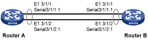
As shown in Figure 2, Router A and Router B are connected through CE1 interfaces, and the links run the PPP protocol. Bind the links into an MP link through binding the links to an MP-group interface.
Analysis
· Configure the CE1 interfaces to operate in channelized CE1 mode, and bind the timeslots of each CE1 interface into a channel set. Then, the system will automatically create synchronous serial interfaces.
· Create an MP-group interface, and assign the synchronous serial interfaces to the MP-group interface for MP bundling.
Restrictions and guidelines
When binding the timeslots of the CE1 interfaces on Router A and Router B, make sure the bound timeslots are consistent on both ends.
Procedures
Configuring Router A
1. Configure CE1 interfaces:
# Configure the clock mode as master for CE1 interface E1 3/1/1. Configure it to operate in channelized CE1 mode, and bind timeslots 1 through 15 of interface E1 3/1/1 into channel set 1. Then, the system will automatically create synchronous serial interface Serial 3/1/1:1.
<RouterA> system-view
[RouterA] controller e1 3/1/1
[RouterA-E1 3/1/1] clock master
[RouterA-E1 3/1/1] using ce1
[RouterA-E1 3/1/1] channel-set 1 timeslot-list 1-15
[RouterA-E1 3/1/1] quit
# Configure the clock mode as master for CE1 interface E1 3/1/2. Configure it to operate in channelized CE1 mode, and bind timeslots 1 through 15 of interface E1 3/1/2 into channel set 1. Then, the system will automatically create synchronous serial interface Serial 3/1/2:1.
[RouterA] controller e1 3/1/2
[RouterA-E1 3/1/2] clock master
[RouterA-E1 3/1/2] using ce1
[RouterA-E1 3/1/2] channel-set 1 timeslot-list 1-15
[RouterA-E1 3/1/2] quit
2. Configure MP bundling:
# Create an MP-group interface, and assign IP address 10.1.1.1/24 to it.
[RouterA] interface mp-group 3/1/1
[RouterA-MP-group3/1/1] ip address 10.1.1.1 24
[RouterA-MP-group3/1/1] quit
# Assign Serial 3/1/1:1 to interface MP-group 3/1/1.
[RouterA] interface serial 3/1/1:1
[RouterA-Serial3/1/1:1] link-protocol ppp
[RouterA-Serial3/1/1:1] ppp mp mp-group 3/1/1
[RouterA-Serial3/1/1:1] undo shutdown
[RouterA-Serial3/1/1:1] quit
# Assign Serial 3/1/2:1 to interface MP-group 3/1/1.
[RouterA] interface serial 3/1/2:1
[RouterA-Serial3/1/2:1] link-protocol ppp
[RouterA-Serial3/1/2:1] ppp mp mp-group 3/1/1
[RouterA-Serial3/1/2:1] undo shutdown
[RouterA-Serial3/1/2:1] quit
Configuring Router B
1. Configure CE1 interfaces:
# Configure CE1 interface E1 3/1/1 to operate in channelized CE1 mode, and bind timeslots 1 through 15 of interface E1 3/1/1 into channel set 1. Then, the system will automatically create synchronous serial interface Serial 3/1/1:1.
<RouterB> system-view
[RouterB] controller e1 3/1/1
[RouterB-E1 3/1/1] using ce1
[RouterB-E1 3/1/1] channel-set 1 timeslot-list 1-15
[RouterB-E1 3/1/1] quit
# Configure CE1 interface E1 3/1/2 to operate in channelized CE1 mode, and bind timeslots 1 through 15 of interface E1 3/1/2 into channel set 1. Then, the system will automatically create synchronous serial interface Serial 3/1/2:1.
[RouterB] controller e1 3/1/2
[RouterB-E1 3/1/2] using ce1
[RouterB-E1 3/1/2] channel-set 1 timeslot-list 1-15
[RouterB-E1 3/1/2] quit
2. Configure MP bundling:
# Create an MP-group interface, and assign IP address 10.1.1.1/24 to it.
[RouterB] interface mp-group 3/1/1
[RouterB-MP-group3/1/1] ip address 10.1.1.2 24
[RouterB-MP-group3/1/1] quit
# Assign Serial 3/1/1:1 to interface MP-group 3/1/1.
[RouterB] interface serial 3/1/1:1
[RouterB-Serial3/1/1:1] link-protocol ppp
[RouterB-Serial3/1/1:1] ppp mp mp-group 3/1/1
[RouterB-Serial3/1/1:1] undo shutdown
[RouterB-Serial3/1/1:1] quit
# Assign Serial 3/1/2:1 to interface MP-group 3/1/1.
[RouterB] interface serial 3/1/2:1
[RouterB-Serial3/1/2:1] link-protocol ppp
[RouterB-Serial3/1/2:1] ppp mp mp-group 3/1/1
[RouterB-Serial3/1/2:1] undo shutdown
[RouterB-Serial3/1/2:1] quit
Verifying the configuration
1. Display MP information on Router A.
[RouterA] display ppp mp
Template: MP-group3/1/1
max-bind: 31, fragment: enabled, min-fragment: 128
Master link: MP-group3/1/1, Active members: 1, Bundle Multilink
Peer's endPoint descriptor: MP-group3/1/1
Sequence format: long (rcv)/long (sent)
Bundle Up Time: 2023/05/16 10:23:08:696
0 lost fragments, 5 reordered, 0 unassigned, 0 interleaved
Sequence: 4 (rcv)/5 (sent)
Active member channels: 1 members
Serial3/1/1:1 Up-Time:2023/05/16 10:23:08:697
Serial3/1/2:1 Up-Time:2023/05/16 10:23:08:700
2. Ping the peer IP address from Router A.
[RouterA] ping 20.1.1.2
Ping 20.1.1.2 (20.1.1.2): 56 data bytes, press CTRL+C to break
56 bytes from 20.1.1.2: icmp_seq=0 ttl=255 time=4.000 ms
56 bytes from 20.1.1.2: icmp_seq=1 ttl=255 time=1.000 ms
56 bytes from 20.1.1.2: icmp_seq=2 ttl=255 time=0.000 ms
56 bytes from 20.1.1.2: icmp_seq=3 ttl=255 time=7.000 ms
56 bytes from 20.1.1.2: icmp_seq=4 ttl=255 time=1.000 ms
--- Ping statistics for 20.1.1.2 ---
5 packet(s) transmitted, 5 packet(s) received, 0.0% packet loss
round-trip min/avg/max/std-dev = 0.000/2.600/7.000/2.577 ms
The output indicates that Router A and Router B have successfully connected through the CE1 interfaces in channelized CE1 mode.
Configuration files
· Router A:
#
controller E1 3/1/1
clock master
channel-set 1 timeslot-list 1-15
#
controller E1 3/1/2
clock master
channel-set 1 timeslot-list 1-15
#
interface Serial3/1/1:1
ppp mp MP-group3/1/1
link-protocol ppp
#
interface Serial3/1/1:1
ppp mp MP-group3/1/1
link-protocol ppp
#
interface MP-group3/1/1
ip address 20.1.1.1 255.255.255.0
#
· Router B:
#
controller E1 3/1/1
channel-set 1 timeslot-list 1-15
#
controller E1 3/1/2
channel-set 1 timeslot-list 1-15
#
interface Serial3/1/1:1
ppp mp MP-group3/1/1
link-protocol ppp
#
interface Serial3/1/2:1
ppp mp MP-group3/1/1
link-protocol ppp
#
interface MP-group3/1/1
ip address 20.1.1.2 255.255.255.0
#
