- Table of Contents
-
- 02-Configuration Examples
- 01-H3C_AAA_Configuration_Examples
- 02-H3C_ACL_Configuration_Examples
- 03-H3C_ATM_Configuration_Examples
- 04-H3C_IGMP_Configuration_Examples
- 05-H3C_IP_Source_Guard_Configuration_Examples
- 06-H3C_Ethernet_OAM_Configuration_Examples
- 07-H3C_NQA_Configuration_Examples
- 08-H3C_QinQ_Configuration_Examples
- 09-H3C_OSPF_Configuration_Examples
- 10-H3C_MPLS_TE_Configuration_Examples
- 11-H3C_OpenFlow_Configuration_Examples
- 12-H3C_NAT_Configuration_Examples
- 13-H3C_RBAC_Configuration_Examples
- 14-H3C_IRF_Configuration_Examples
- 15-H3C_POS_Interface_Configuration_Examples
- 16-H3C_CPOS_Interface_Configuration_Examples
- 17-H3C_DHCP_Relay_Redundancy_Configuration_Examples
- 18-H3C_DLDP_Configuration_Examples
- 19-H3C_IS-IS_Configuration_Examples
- 20-H3C_MPLS_L3VPN_Configuration_Examples
- 21-H3C_SSH_Configuration_Examples
- 22-H3C_Login_Management_Configuration_Examples
- 23-H3C_SNMP_Configuration_Examples
- 24-H3C_Priority_Marking_and_Queue_Scheduling_Configuration_Examples
- 25-H3C_Multicast_VPN_Configuration_Examples
- 26-H3C_BGP_Configuration_Examples
- 27-H3C_HoVPN_Configuration_Examples
- 28-H3C_L2TP_Configuration_Examples
- 29-H3C_VRRP_Configuration_Examples
- 30-H3C_Traffic_Filtering_Configuration_Examples
- 31-H3C_Samplers_and_IPv4_NetStream_Configuration_Examples
- 32-H3C_Software_Upgrade_Examples
- 33-H3C_MPLS_L2VPN_Configuration_Examples
- 34-H3C_NetStream_Configuration_Examples
- 35-H3C_Policy-Based_Routing_Configuration_Examples
- 36-H3C_Traffic_Policing_Configuration_Examples
- 37-H3C_BFD_Configuration_Examples
- 38-H3C_OSPFv3_Configuration_Examples
- 39-H3C_VPLS_Configuration_Examples
- 40-H3C_GTS_and_Rate_Limiting_Configuration_Examples
- 41-H3C_IPv6_IS-IS_Configuration_Examples
- 42-H3C_MPLS OAM_Configuration_Examples
- 43-H3C_BGP_Route_Selection_Configuration_Examples
- 44-H3C_IS-IS_Route_Summarization_Configuration_Examples
- 45-H3C_SRv6 Configuration Examples
- 46-H3C_Attack_Protection_Configuration_Examples
- 47-H3C_OSPF_Multi-Process_Configuration_Examples
- 48-H3C_OSPF_with_Multi-Instance_Configuration_Examples
- 49-H3C_ARP_Attack_Protection_Configuration_Examples
- 50-H3C_DHCPv6_Server_and_DHCPv6_Prefix_Client_Configuration_Examples
- 51-CE1 Interface Connection Configuration Examples
- 52-GRE Tunnel Establishment Using OSPF Configuration Examples
- 53-GRE Tunnel Establishment Using Static Routes Configuration Examples
- 54-OSPF over IPsec for Overseas Branch Access Configuration Examples
- 55-General QoS Configuration Examples
- 56-QoS Configuration Examples for the Financial Industry
- Related Documents
-
| Title | Size | Download |
|---|---|---|
| 12-H3C_NAT_Configuration_Examples | 432.63 KB |
Example: Configuring basic NAT
Specifying IP addresses for the interfaces
Configuring outbound NAT for internal users
Implementing load sharing among FTP servers
Specifying a NAT-capable service module to provide NAT service
Configuring a QoS policy to redirect traffic to the service module in slot 3
Example: Configuring NAT Server for external-to-internal access
Example: Configuring internal users to access the external network through a VPN and NAT addresses
Example: Configuring DS-Lite support for PPPoE collaboration
Example: Configuring bidirectional NAT and NAT Server with easy IP
Example: Configuring bidirectional NAT and NAT Server
Example: Configuring internal users to access external Web servers by using NAT addresses
Introduction
This document provides NAT configuration examples.
Prerequisites
This document is not restricted to specific software or hardware versions.
The configuration examples in this document were created and verified in a lab environment, and all the devices were started with the factory default configuration. When you are working on a live network, make sure you understand the potential impact of every command on your network.
The following information is provided based on the assumption that you have basic knowledge of NAT.
Restrictions and guidelines
NAT is available on service modules except CSPC-CP2LB.
A QoS policy is required on an interface to redirect the incoming traffic to the specified NAT-capable service module. For more information about QoS policies, see ACL and QoS Configuration Guide.
Example: Configuring basic NAT
Network configuration
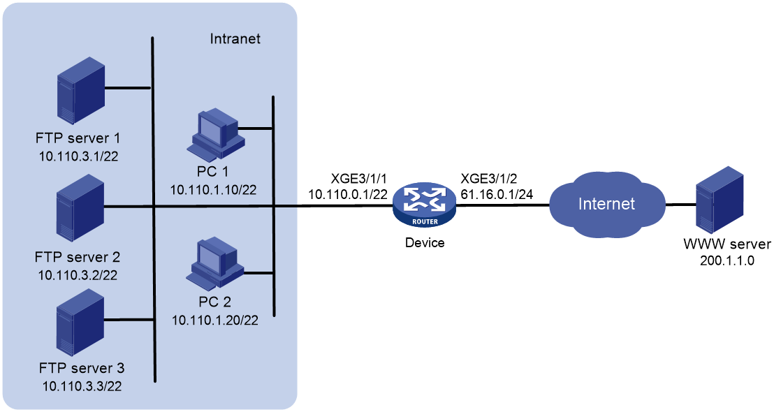
As shown in Figure 1, the internal users use the IP addresses in the range of 10.110.0.0 to 10.110.2.255. The private IP addresses of the FTP servers are from 10.110.3.1 to 10.110.3.3. These servers provide FTP services to external users. The company has three public IP addresses from 61.16.0.1 to 61.16.0.3.
Configure NAT on the device to implement the following:
· Allow the internal and external users to use the IP address 61.16.0.1 to access the FTP servers.
· Implement load sharing among the FTP servers and do not allow connections that are initiated by the FTP servers to the external network.
Analysis
· To translate IP addresses in the range of 10.110.0.0 to 10.110.2.255 into IP addresses in the range of 61.16.0.2 to 61.16.0.3, configure an ACL to identify these packets. Then configure outbound address translation on packets identified by the ACL on Ten-GigabitEthernet 3/1/2.
· To allow three FTP servers to load share services, configure NAT server group to implement load sharing.
· To allow internal hosts to access the internal FTP server by using a public IP address, enable AT hairpin on Ten-GigabitEthernet 3/1/1 of the device.
Procedures
Specifying IP addresses for the interfaces
# Specify IP addresses for Ten-GigabitEthernet 3/1/1 and Ten-GigabitEthernet 3/1/2.
<Device> system-view
[Device] interface Ten-GigabitEthernet3/1/1
[Device-Ten-GigabitEthernet3/1/1] ip address 10.110.0.1 255.255.252.0
[Device-Ten-GigabitEthernet3/1/1] quit
[Device] interface Ten-GigabitEthernet3/1/2
[Device-Ten-GigabitEthernet3/1/2] ip address 61.16.0.1 255.255.255.0
[Device-Ten-GigabitEthernet3/1/2] quit
Configuring outbound NAT for internal users
# Configure NAT address group 0, and add public IP address 61.16.0.2 and 61.16.0.3 to the group.
[Device-nat-address-group-0] address 61.16.0.2 61.16.0.3
[Device-nat-address-group-0] quit
# Configure ACL 2000 to identify packets only from subnet 10.110.0.0 to 10.110.2.255.
[Device-acl-ipv4-basic-2000] rule permit source 10.110.0.0 0.0.1.255
[Device-acl-ipv4-basic-2000] rule permit source 10.110.2.0 0.0.0.255
[Device-acl-ipv4-basic-2000] quit
# Configure outbound dynamic NAT on Ten-GigabitEthernet 3/1/2 to translate source IP address in packets permitted by ACL 2000 into the IP addresses in NAT address group 0.
[Device] interface Ten-GigabitEthernet3/1/2
[Device-Ten-GigabitEthernet3/1/2] nat outbound 2000 address-group 0
[Device-Ten-GigabitEthernet3/1/2] quit
Implementing load sharing among FTP servers
# Create NAT server group 0, and add servers at 10.110.3.1, 10.110.3.2, 10.110.3.3 to the group.
[Device-nat-server-group-0] inside ip 10.110.3.1 port 21
[Device-nat-server-group-0] inside ip 10.110.3.2 port 21
[Device-nat-server-group-0] inside ip 10.110.3.3 port 21
[Device-nat-server-group-0] quit
# Associate NAT server group 0 with Ten-GigabitEthernet 3/1/2 so that servers in the server group can load share FTP services.
[Device] interface Ten-GigabitEthernet3/1/2
[Device-Ten-GigabitEthernet3/1/2] nat server protocol tcp global 61.16.0.1 ftp inside server-group 0
# Enable NAT hairpin on Ten-GigabitEthernet 3/1/1.
[Device] interface Ten-GigabitEthernet3/1/1
[Device-Ten-GigabitEthernet3/1/1] nat hairpin enable
Specifying a NAT-capable service module to provide NAT service
# Specify the service module in slot 3 to provide the NAT service for Ten-GigabitEthernet 3/1/1.
[Device-Ten-GigabitEthernet3/1/1] nat service slot 3
[Device-Ten-GigabitEthernet3/1/1] quit
# Specify the service module in slot 3 to provide the NAT service for Ten-GigabitEthernet 3/1/2.
[Device] interface Ten-GigabitEthernet3/1/2
[Device-Ten-GigabitEthernet3/1/2] nat service slot 3
[Device-Ten-GigabitEthernet3/1/2] quit
Configuring a QoS policy to redirect traffic to the service module in slot 3
# Configure ACL 2001 to identify packets to be redirected to the NAT-capable service module. In this example, the packets are those to be translated, therefore, define the same ACL rules as those in ACL 2000.
[Device] acl basic 2001
[Device-acl-ipv4-basic-2001] rule permit source 10.110.0.0 0.0.1.255
[Device-acl-ipv4-basic-2001] rule permit source 10.110.2.0 0.0.0.255
[Device-acl-ipv4-basic-2001] quit
# Create traffic class 1 and define a match criterion for the traffic class to match ACL 2001.
[Device] traffic classifier 1 operator and
[Device-classifier-1] if-match acl 2001
[Device-classifier-1] quit
# Create traffic behavior 1 and configure redirecting traffic to the service module in slot 3 in the traffic behavior 1.
[Device] traffic behavior 1
[Device-behavior-1] redirect slot 3
[Device-behavior-1] quit
# Create QoS policy 1 and associate traffic class 1 with traffic behavior 1 in the QoS policy.
[Device] qos policy 1
[Device-qospolicy-1] classifier 1 behavior 1
[Device-qospolicy-1] quit
# Apply the QoS policy to the inbound direction of Ten-GigabitEthernet 3/1/1.
[Device] interface Ten-GigabitEthernet3/1/1
[Device-Ten-GigabitEthernet3/1/1] qos apply policy 1 inbound
[Device-Ten-GigabitEthernet3/1/1] quit
Verifying the configuration
# Access the WWW server from PC 1. Verify that a NAT session is created on the device.
[Device] display nat session verbose
Initiator:
Source IP/port: 10.110.1.10/1024
Destination IP/port: 200.1.1.10/80
DS-Lite tunnel peer: -
VPN instance/VLAN ID/Inline ID: -/-/-
Protocol: TCP(6)
Inbound interface: Ten-GigabitEthernet3/1/1
Responder:
Source IP/port: 200.1.1.10/80
Destination IP/port: 61.16.0.2/1025
DS-Lite tunnel peer: -
VPN instance/VLAN ID/Inline ID: -/-/-
Protocol: TCP(6)
Inbound interface: Ten-GigabitEthernet3/1/2
State: TCP_CLOSE
Application: HTTP
Role: -
Failover group ID: -
Start time: 2014-07-08 13:30:47
Initiator->Responder: 0 packets 0 bytes
Responder->Initiator: 0 packets 0 bytes
Total sessions found: 1
# Use two external hosts at the IP address of 61.16.0.10 and 61.16.0.11 to request FTP services at the same time. On the device, verify that two NAT sessions are created, and FTP server 1 and FTP server 2 provide FTP services for the two hosts, respectively.
[Device] display nat session verbose
Initiator:
Source IP/port: 61.16.0.11/1024
Destination IP/port: 61.16.0.1/21
DS-Lite tunnel peer: -
VPN instance/VLAN ID/Inline ID: -/-/-
Protocol: TCP(6)
Inbound interface: Ten-GigabitEthernet3/1/2
Responder:
Source IP/port: 10.110.3.1/21
Destination IP/port: 61.16.0.11/1024
DS-Lite tunnel peer: -
VPN instance/VLAN ID/Inline ID: -/-/-
Protocol: TCP(6)
Inbound interface: Ten-GigabitEthernet3/1/1
State: TCP_ESTABLISHED
Application: FTP
Role: -
Failover group ID: -
Start time: 2014-07-08 14:11:41
Initiator->Responder: 0 packets 0 bytes
Responder->Initiator: 0 packets 0 bytes
Initiator:
Source IP/port: 61.16.0.10/1024
Destination IP/port: 61.16.0.1/21
DS-Lite tunnel peer: -
VPN instance/VLAN ID/Inline ID: -/-/-
Protocol: TCP(6)
Inbound interface: Ten-GigabitEthernet3/1/2
Responder:
Source IP/port: 10.110.3.2/21
Destination IP/port: 61.16.0.10/1024
DS-Lite tunnel peer: -
VPN instance/VLAN ID/Inline ID: -/-/-
Protocol: TCP(6)
Inbound interface: Ten-GigabitEthernet3/1/1
State: TCP_ESTABLISHED
Application: FTP
Role: -
Failover group ID: -
Start time: 2014-07-08 14:12:00
Initiator->Responder: 0 packets 0 bytes
Responder->Initiator: 0 packets 0 bytes
Total sessions found: 2
# Access an FTP server through 61.16.0.1 from PC 1. Verify that a NAT session is created.
[Device] display nat session verbose
Initiator:
Source IP/port: 10.110.1.10/1024
Destination IP/port: 61.16.0.1/21
DS-Lite tunnel peer: -
VPN instance/VLAN ID/Inline ID: -/-/-
Protocol: TCP(6)
Inbound interface: Ten-GigabitEthernet3/1/1
Responder:
Source IP/port: 10.110.3.1/21
Destination IP/port: 61.16.0.2/1025
DS-Lite tunnel peer: -
VPN instance/VLAN ID/Inline ID: -/-/-
Protocol: TCP(6)
Inbound interface: Ten-GigabitEthernet3/1/1
State: TCP_ESTABLISHED
Application: FTP
Role: -
Failover group ID: -
Start time: 2014-07-08 14:24:15
Initiator->Responder: 0 packets 0 bytes
Responder->Initiator: 0 packets 0 bytes
Total sessions found: 1
Configuration files
#
traffic classifier 1 operator and
if-match acl 2001
#
traffic behavior 1
redirect slot 3
#
qos policy 1
classifier 1 behavior 1
#
interface Ten-GigabitEthernet3/1/1
ip address 10.110.0.1 255.255.252.0
qos apply policy 1 inbound
nat hairpin enable
nat service slot 3
#
interface Ten-GigabitEthernet3/1/2
ip address 61.16.0.1 255.255.255.0
nat outbound 2000 address-group 0
nat server protocol tcp global 61.16.0.1 21 inside server-group 0
nat service slot 3
#
acl basic 2000
rule 0 permit source 10.110.0.0 0.0.1.255
rule 5 permit source 10.110.2.0 0.0.0.255
#
acl basic 2001
rule 0 permit source 10.110.0.0 0.0.1.255
rule 5 permit source 10.110.2.0 0.0.0.255
#
address 61.16.0.2 61.16.0.3
#
nat server-group 0
inside ip 10.110.3.1 port 21
inside ip 10.110.3.2 port 21
inside ip 10.110.3.3 port 21
#
Example: Configuring NAT Server for external-to-internal access
Network configuration
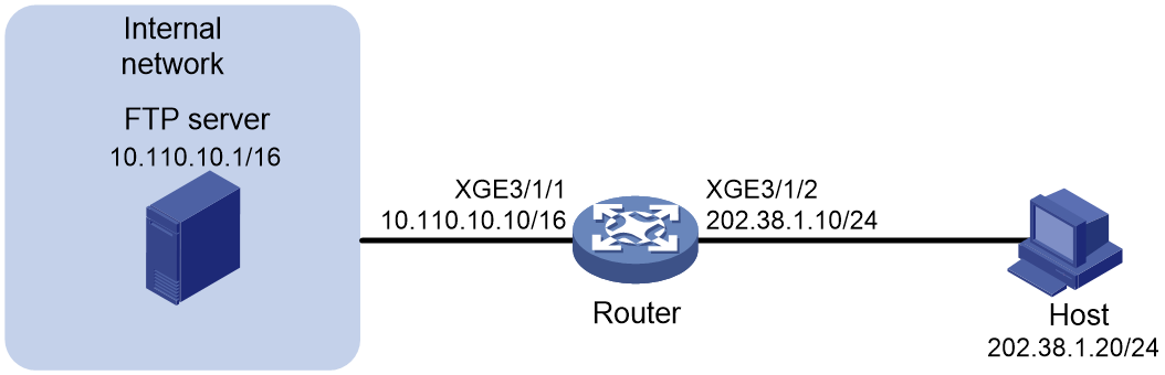
As shown in Figure 2, a company uses private IP addresses on network 10.110.10.1/16 and public IP address 202.38.1.1. Configure NAT dynamic port block mapping to allow external hosts to access the internal FTP server by IP address 202.38.1.1 and port number 21.
Procedures
Configuring the router
Assigning IP addresses to interfaces
<Router> system-view
[Router] interface Ten-GigabitEthernet3/1/1
[Router-Ten-GigabitEthernet3/1/1] ip address 10.110.10.10 255.255.0.0
[Router-Ten-GigabitEthernet3/1/1] quit
[Router] interface Ten-GigabitEthernet3/1/2
[Router-Ten-GigabitEthernet3/1/2] ip address 202.38.1.10 255.255.255.0
[Router-Ten-GigabitEthernet3/1/2] quit
Configuring a failover group
# Specify the CGN card in slot 2 as the primary node in failover group cgn1.
[Router] failover group cgn1 id 1
[Router-failover-group-cgn] bind slot 2 primary
[Router-failover-group-cgn] quit
Configuring an ACL
# Configure ACL 3000 to identify packets from IP address 10.110.10.1.
[Router] acl advanced 3000
[Router-acl-ipv4-adv-3000] rule 5 permit ip source 10.110.10.1 0
[Router-acl-ipv4-adv-3000] quit
Configuring a QoS policy to redirect IP packets to the NAT instance
# Configure traffic class cgn to identify IP packets.
[Router] traffic classifier cgn operator and
[Router-classifier-cgn] if-match acl 3000
[Router-classifier-cgn] quit
# Configure traffic behavior cgn to bind the matching traffic to NAT instance a.
[Router] traffic behavior cgn
[Router-behavior-cgn] bind nat-instance a
[Router-behavior-cgn] quit
# Create QoS policy cgn and associate the traffic class with the traffic behavior.
[Router] qos policy cgn
[Router-qospolicy-cgn] classifier cgn behavior cgn
[Router-qospolicy-cgn] quit
# Apply QoS policy to the inbound traffic on Ten-GigabitEthernet 3/1/1.
[Router] interface Ten-GigabitEthernet3/1/1
[Router-Ten-GigabitEthernet3/1/1] qos apply policy cgn inbound
[Router-Ten-GigabitEthernet3/1/1] quit
Configuring a service instance group
# Create service instance group 1 and associate it with failover group cgn1.
[Router] service-instance-group 1
[Router-service-instance-group-1] failover-group cgn1
[Router-service-instance-group-1] quit
Configuring global NAT
# Create a NAT instance named a with ID 1.
[Router] nat instance a id 1
# Associate NAT instance a with service instance group 1.
[Router-nat-instance-a] service-instance-group 1
# Configure NAT server to allow external hosts to access the internal FTP server by using address 202.38.1.1 and port number 21.
[Router-nat-instance-a] nat server protocol tcp global 202.38.1.1 21 inside 10.110.10.1 ftp
[Router-nat-instance-a] quit
Configuring the host
Configure 202.38.1.10 as the default gateway address for the host.
Verifying the configuration
# Verify that the host on the external network can access the internal server by using the public address. (Details not shown.)
# Display detailed information about NAT sessions.
<Router> display nat session verbose
Initiator:
Source IP/port: 202.38.1.20/53323
Destination IP/port: 202.38.1.1/21
DS-Lite tunnel peer: -
VPN instance/VLAN ID/Inline ID: -/-/-
Protocol: TCP(6)
Inbound interface: Ten-GigabitEthernet3/1/2
Responder:
Source IP/port: 10.110.10.1/21
Destination IP/port: 202.38.1.20/53323
DS-Lite tunnel peer: -
VPN instance/VLAN ID/Inline ID: -/-/-
Protocol: TCP(6)
Inbound interface: Ten-GigabitEthernet3/1/1
State: TCP_ESTABLISHED
Application: FTP
Role: Master
Failover group ID: 1
Start time: 2022-05-19 14:02:28
Initiator->Responder: 0 packets 0 bytes
Responder->Initiator: 0 packets 0 bytes
Total sessions found: 1
Configuration files
#
failover group cgn1 id 1
bind slot 2 primary
#
traffic classifier cgn operator and
if-match acl 3000
#
traffic behavior cgn
bind nat-instance a
#
qos policy cgn
classifier cgn behavior cgn
#
interface Ten-GigabitEthernet3/1/1
ip address 10.110.10.10 255.255.0.0
qos apply policy cgn inbound
#
interface Ten-GigabitEthernet3/1/2
ip address 202.38.1.10 255.255.255.0
#
acl advanced 3000
rule 5 permit ip source 10.110.10.1 0
#
service-instance-group 1
failover-group cgn1
#
nat instance a id 1
service-instance-group 1
nat server protocol tcp global 202.38.1.1 21 inside 10.110.10.1 21
#
Example: Configuring internal users to access the external network through a VPN and NAT addresses
Network configuration
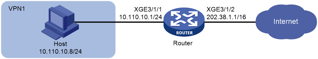
As shown in Figure 3, a company deploys VPN services in the internal network to provide an isolated private network so that employees can access internal resources securely.
For the employees to access the Internet through the VPN, configure NAT to translate private IP addresses in the internal network into public IP addresses. Plan and configure a NAT address group. The IP addresses in the address group are used by the VPN client for public network access. This makes sure all external traffic destined for the VPN can be correctly routed and translated.
Procedures
Configuring the router
1. Configure a VPN instance:
# Create a VPN instance named vpn1, and configure a route distinguisher and route targets for the VPN instance.
[Router] ip vpn-instance vpn1
[Router-vpn-instance-vpn1] route-distinguisher 100:200
[Router-vpn-instance-vpn1] vpn-target 100:200 import-extcommunity
[Router-vpn-instance-vpn1] vpn-target 100:200 export-extcommunity
[Router-vpn-instance-vpn1] quit
# Associate Ten-GigabitEthernet 3/1/1Ten-GigabitEthernet3/1/1 with VPN instance vpn1.
[Router] interface Ten-GigabitEthernet3/1/1
[Router-Ten-GigabitEthernet3/1/1] ip binding vpn-instance vpn1
[Router-Ten-GigabitEthernet3/1/1] quit
2. Assign IP addresses to interfaces:
# Assign IP addresses to interfaces according to the network diagram.
<Router> system-view
[Router] interface Ten-GigabitEthernet3/1/1
[Router-Ten-GigabitEthernet3/1/1] ip address 10.110.10.1 255.255.255.0
[Router-Ten-GigabitEthernet3/1/1] quit
[Router] interface Ten-GigabitEthernet3/1/2
[Router-Ten-GigabitEthernet3/1/2] port link-mode route
[Router-Ten-GigabitEthernet3/1/2] ip address 202.38.1.1 255.255.0.0
[Router-Ten-GigabitEthernet3/1/2] quit
3. Create a NAT instance.
[Router] nat instance a id 1
[Router-nat-instance-a] quit
4. Configure static routes.
[Router] ip route-static vpn-instance vpn1 0.0.0.0 0 202.38.1.2 public
[Router] ip route-static vpn-instance vpn1 10.0.0.0 8 Ten-GigabitEthernet3/1/1Ten-GigabitEthernet3/1/1
5. Specify the primary and secondary nodes for the failover group.
[Router] failover group cgn1 id 1
[Router-failover-group-cgn1] bind slot 9 primary
[Router-failover-group-cgn1] bind slot 12 secondary
[Router-failover-group-cgn1] quit
6. Configure ACL 2000 to allow address translation only for user packets from internal network 10.110.10.0/24 in VPN instance vpn1.
[Router] acl basic 2000
[Router-acl-basic-2000] rule 5 permit vpn-instance vpn1 source 10.110.10.0 0.0.0.255
[Router-acl-basic-2000] quit
7. Configure a QoS policy to redirect traffic to the NAT instance:
# Configure traffic class cgn and traffic behavior cgn to redirect packets matching ACL 2000 to NAT instance a.
[Router] traffic classifier cgn operator and
[Router-classifier-cgn] if-match acl 2000
[Router-classifier-cgn] quit
[Router] traffic behavior cgn
[Router-behavior-cgn] bind nat-instance a
[Router-behavior-cgn] quit
# Create QoS policy cgn and associate the traffic class with the traffic behavior.
[Router] qos policy cgn
[Router-qospolicy-cgn] classifier cgn behavior cgn
[Router-qospolicy-cgn] quit
# Apply QoS policy cgn to the inbound traffic on Ten-GigabitEthernet 3/1/1Ten-GigabitEthernet3/1/1.
[Router] interface Ten-GigabitEthernet3/1/1
[Router-Ten-GigabitEthernet3/1/1] qos apply policy cgn inbound
[Router-Ten-GigabitEthernet3/1/1] quit
8. Create service instance group 1 and associate it with failover group cgn1.
[Router] service-instance-group 1
[Router-service-instance-group-1] failover-group cgn1
[Router-service-instance-group-1] quit
9. Configure global NAT:
# Create address group 1, set the port range to 1024 to 65535, and add public IP addresses 202.38.1.3 and 202.38.1.4 to the address group.
[Router] nat address-group 1
[Router-nat-address-group-1] port-range 1024 65535
[Router-nat-address-group-1] address 202.38.1.3 202.38.1.4
[Router-nat-address-group-1] quit
# Associate NAT instance a with service instance group 1.
[Router] nat instance a id 1
[Router-nat-instance-a] service-instance-group 1
# Configure an outbound PAT rule in NAT instance a to translate the source addresses of outgoing packets permitted by ACL 2000 into the addresses in address group 1.
[Router-nat-instance-a] nat outbound 2000 address-group 1
[Router-nat-instance-a] quit
Configuring the host
Configure 10.110.10.1 as the default gateway address for the host.
Verifying the configuration
# Display detailed information about NAT sessions generated when the host accesses the Internet.
[Router] display nat session verbose
Initiator:
Source IP/port: 10.110.10.2/1024
Destination IP/port: 202.38.1.2/1024
DS-Lite tunnel peer: -
VPN instance/VLAN ID/Inline ID: vpn1/-/-
Protocol: TCP(6)
Inbound interface: Ten-GigabitEthernet3/1/1
Responder:
Source IP/port: 202.38.1.2/1024
Destination IP/port: 202.38.1.4/1026
DS-Lite tunnel peer: -
VPN instance/VLAN ID/Inline ID: -/-/-
Protocol: TCP(6)
Inbound interface: Ten-GigabitEthernet3/1/2
State: TCP_ESTABLISHED
Application: OTHER
Role: Master
Failover group ID: 1
Start time: 2024-11-20 16:01:00
Initiator->Responder: 0 packets 0 bytes
Responder->Initiator: 0 packets 0 bytes
Total sessions found: 1
Configuration files
#
failover group cgn1 id 1
bind slot 9 primary
bind slot 12 secondary
#
ip vpn-instance vpn1
route-distinguisher 100:200
vpn-target 100:200 import-extcommunity
vpn-target 100:200 export-extcommunity
#
traffic classifier cgn operator and
if-match acl 2000
#
traffic behavior cgn
bind nat-instance a
#
qos policy cgn
classifier cgn behavior cgn
#
interface Ten-GigabitEthernet3/1/1
ip binding vpn-instance vpn1
ip address 10.110.10.1 255.255.255.0
qos apply policy cgn inbound
#
interface Ten-GigabitEthernet3/1/2
port link-mode route
ip address 202.38.1.1 255.255.0.0
#
ip route-static vpn-instance vpn1 0.0.0.0 0 202.38.1.2 public
ip route-static vpn-instance vpn1 10.0.0.0 8 Ten-GigabitEthernet3/1/1
#
acl basic 2000
rule 5 permit vpn-instance vpn1 source 10.110.10.0 0.0.0.255
#
service-instance-group 1
failover-group cgn1
#
nat address-group 1
port-range 1024 65535
address 202.38.1.3 202.38.1.4
#
nat instance a id 1
service-instance-group 1
nat outbound 2000 address-group 1
#
Example: Configuring VPN users to use specific addresses to access servers in the VPN on an MPLS L3VPN network
Network configuration
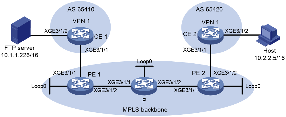
As shown in Figure 4, CE 1 and CE 2 belong to VPN 1 on the MPLS L3VPN network. Configure the routers to enable the private host connected to CE 2 to access the internal FTP server connected to CE 1.
|
Device |
Interface |
IP address |
Device |
Interface |
IP address |
|
CE 1 |
XGE3/1/1XGE3/1/1 |
172.16.1.1/24 |
CE 2 |
XGE3/1/1XGE3/1/1 |
172.16.4.1/24 |
|
|
XGE3/1/2XGE3/1/2 |
10.1.1.240/16 |
|
XGE3/1/2XGE3/1/2 |
10.2.2.240/16 |
|
PE 1 |
Loop1 |
1.1.1.9/32 |
PE 2 |
Loop1 |
3.3.3.9/32 |
|
|
XGE3/1/1XGE3/1/1 |
172.16.1.2/24 |
|
XGE3/1/1XGE3/1/1 |
172.16.3.1/24 |
|
|
XGE3/1/2XGE3/1/2 |
172.16.2.2/24 |
|
XGE3/1/2XGE3/1/2 |
172.16.4.2/24 |
|
P |
Loop1 |
2.2.2.9.32 |
|
|
|
|
|
XGE3/1/1XGE3/1/1 |
172.16.2.1/24 |
|
|
|
|
|
XGE3/1/2XGE3/1/2 |
172.16.3.2/24 |
|
|
|
Procedures
Configuring PE 1
# Configure OSPF to implement communication between the PE and the P device.
<Sysname> system-view
[Sysname] sysname PE1
[PE1] interface ten-gigabitethernet 3/1/2
[PE1-Ten-GigabitEthernet3/1/2] ip address 172.16.2.2 255.255.255.0
[PE1-Ten-GigabitEthernet3/1/2] quit
[PE1] interface LoopBack 0
[PE1-LoopBack0] ip address 1.1.1.9 255.255.255.255
[PE1-LoopBack0] quit
[PE1] ospf
[PE1-ospf-1] area 0.0.0.0
[PE1-ospf-1-area-0.0.0.0] network 172.16.2.0 0.0.0.255
[PE1-ospf-1-area-0.0.0.0] network 1.1.1.9 0.0.0.0
[PE1-ospf-1-area-0.0.0.0] quit
[PE1-ospf-1] quit
# Configure basic MPLS and MPLS LDP on the MPLS backbone to establish LDP LSPs.
[PE1] mpls lsr-id 1.1.1.9
[PE1] mpls ldp
[PE1-ldp] quit
[PE1] interface ten-gigabitethernet 3/1/2
[PE1-Ten-GigabitEthernet3/1/2] mpls enable
[PE1-Ten-GigabitEthernet3/1/2] mpls ldp enable
[PE1-Ten-GigabitEthernet3/1/2] quit
# Configure a VPN instance on PE 1 to allow CE 1 access to PE 1.
[PE1] ip vpn-instance vpn1
[PE1-vpn-instance-vpn1] route-distinguisher 100:1
[PE1-vpn-instance-vpn1] vpn-target 111:1 import-extcommunity
[PE1-vpn-instance-vpn1] vpn-target 111:1 export-extcommunity
[PE1-vpn-instance-vpn1] quit
[PE1] interface ten-gigabitethernet 3/1/1
[PE1-Ten-GigabitEthernet3/1/1] ip binding vpn-instance vpn1
[PE1-Ten-GigabitEthernet3/1/1] ip address 172.16.1.2 255.255.255.0
[PE1-Ten-GigabitEthernet3/1/1] quit
# Establish an EBGP peer relationship between PE 1 and CE 1, and redistribute VPN routes.
[PE1] bgp 100
[PE1-bgp-default] ip vpn-instance vpn1
[PE1-bgp-default-vpn1] peer 172.16.1.1 as-number 65410
[PE1-bgp-default-vpn1] address-family ipv4 unicast
[PE1-bgp-default-ipv4-vpn1] peer 172.16.1.1 enable
[PE1-bgp-default-ipv4-vpn1] import-route direct
[PE1-bgp-default-ipv4-vpn1] import-route unr
[PE1-bgp-default-ipv4-vpn1] quit
[PE1-bgp-default-vpn1] quit
[PE1-bgp-default] quit
# Establish an MP-IBGP peer relationship between PE 1 and PE 2.
[PE1] bgp 100
[PE1-bgp-default] peer 3.3.3.9 as-number 100
[PE1-bgp-default] peer 3.3.3.9 connect-interface loopback 0
[PE1-bgp-default] address-family vpnv4
[PE1-bgp-default-vpnv4] peer 3.3.3.9 enable
[PE1-bgp-default-vpnv4] quit
[PE1-bgp-default] quit
# Specify the CGN card in slot 2 as the primary node in failover group cgn1.
[PE1] failover group cgn1 id 1
[PE1-failover-group-cgn] bind slot 2 primary
[PE1-failover-group-cgn] quit
# Create service instance group 1 and associate it with failover group cgn1.
[PE1] service-instance-group 1
[PE1-service-instance-group 1] failover-group cgn1
[PE1-service-instance-group 1] quit
# Create a NAT instance named a.
[PE1] nat instance a id 1
# Associate NAT instance a with service instance group 1.
[PE1-nat-instance-1] service-instance-group 1
[PE1-nat-instance-1] quit
# Configure ACL 3000 to identify packets from subnet 10.1.0.0/16.
[PE1] acl advanced 3000
[PE1-acl-ipv4-adv-3000] rule 5 permit ip vpn-instance vpn1 source 10.1.0.0 0.0.255.255
[PE1-acl-ipv4-adv-3000] quit
# Configure traffic class cgn and traffic behavior cgn to redirect packets matching ACL 3000 to NAT instance a.
[PE1] traffic classifier cgn operator and
[PE1-classifier-cgn] if-match acl 3000
[PE1-classifier-cgn] quit
[PE1] traffic behavior cgn
[PE1-behavior-cgn] bind nat-instance a
[PE1-behavior-cgn] quit
# Create QoS policy cgn and associate the traffic class with the traffic behavior.
[PE1] qos policy cgn
[PE1-qospolicy-cgn] classifier cgn behavior cgn
[PE1-qospolicy-cgn] quit
# Apply QoS policy cgn to the inbound traffic on Ten-GigabitEthernet 3/1/1Ten-GigabitEthernet3/1/1.
[PE1] interface ten-gigabitethernet 3/1/1
[PE1-Ten-GigabitEthernet3/1/1] qos apply policy cgn inbound
[PE1-Ten-GigabitEthernet3/1/1] quit
# Configure a NAT server mapping.
[PE1] nat instance a
[PE1-nat-instance-a] nat server protocol tcp global 11.1.1.2 21 vpn-instance vpn1 inside 10.1.1.226 21 vpn-instance vpn1
[PE1-nat-instance-a] quit
Configuring the P device
# Configure OSPF to implement communication between PEs and the P device.
<Sysname> system-view
[Sysname] sysname P
[P] interface loopback 0
[P-LoopBack0] ip address 2.2.2.9 32
[P-LoopBack0] quit
[P] interface ten-gigabitethernet 3/1/1
[P-Ten-GigabitEthernet3/1/1] ip address 172.16.2.1 255.255.255.0
[P-Ten-GigabitEthernet3/1/1] quit
[P] interface ten-gigabitethernet 3/1/2
[P-Ten-GigabitEthernet3/1/2] ip address 172.16.3.2 255.255.255.0
[P-Ten-GigabitEthernet3/1/2] quit
[P] ospf
[P-ospf-1] area 0
[P-ospf-1-area-0.0.0.0] network 172.16.2.0 0.0.0.255
[P-ospf-1-area-0.0.0.0] network 172.16.3.0 0.0.0.255
[P-ospf-1-area-0.0.0.0] network 2.2.2.9 0.0.0.0
[P-ospf-1-area-0.0.0.0] quit
[P-ospf-1] quit
# Configure basic MPLS and MPLS LDP on the MPLS backbone to establish LDP LSPs.
[P] mpls lsr-id 2.2.2.9
[P] mpls ldp
[P-ldp] quit
[P] interface ten-gigabitethernet 3/1/1
[P-Ten-GigabitEthernet3/1/1] mpls enable
[P-Ten-GigabitEthernet3/1/1] mpls ldp enable
[P-Ten-GigabitEthernet3/1/1] quit
[P] interface ten-gigabitethernet 3/1/2
[P-Ten-GigabitEthernet3/1/2] mpls enable
[P-Ten-GigabitEthernet3/1/2] mpls ldp enable
[P-Ten-GigabitEthernet3/1/2] quit
Configuring PE 2
# Configure OSPF to implement communication between the PE and the P device.
<Sysname> system-view
[Sysname] sysname PE2
[PE2] interface ten-gigabitethernet 3/1/1
[PE2-Ten-GigabitEthernet3/1/1] ip address 172.16.3.1 255.255.255.0
[PE2-Ten-GigabitEthernet3/1/1] quit
[PE2] interface LoopBack 0
[PE2-LoopBack0] ip address 3.3.3.9 255.255.255.255
[PE2-LoopBack0] quit
[PE2] ospf
[PE2-ospf-1] area 0.0.0.0
[PE2-ospf-1-area-0.0.0.0] network 172.16.3.0 0.0.0.255
[PE2-ospf-1-area-0.0.0.0] network 3.3.3.9 0.0.0.0
[PE2-ospf-1-area-0.0.0.0] quit
[PE2-ospf-1] quit
# Configure basic MPLS and MPLS LDP on the MPLS backbone to establish LDP LSPs.
[PE2] mpls lsr-id 3.3.3.9
[PE2] mpls ldp
[PE2-ldp] quit
[PE2] interface ten-gigabitethernet 3/1/1
[PE2-Ten-GigabitEthernet3/1/1] mpls enable
[PE2-Ten-GigabitEthernet3/1/1] mpls ldp enable
[PE2-Ten-GigabitEthernet3/1/1] quit
# Configure a VPN instance on PE 2 to allow CE 2 access to PE 2.
[PE2] ip vpn-instance vpn1
[PE2-vpn-instance-vpn1] route-distinguisher 200:1
[PE2-vpn-instance-vpn1] vpn-target 111:1 import-extcommunity
[PE2-vpn-instance-vpn1] vpn-target 111:1 export-extcommunity
[PE2-vpn-instance-vpn1] quit
[PE2] interface ten-gigabitethernet 3/1/2
[PE2-Ten-GigabitEthernet3/1/2] ip binding vpn-instance vpn1
[PE2-Ten-GigabitEthernet3/1/2] ip address 172.16.4.2 255.255.255.0
[PE2-Ten-GigabitEthernet3/1/2] quit
# Establish an EBGP peer relationship between PE 2 and CE 2, and redistribute VPN routes.
[PE2] bgp 100
[PE2-bgp-default] ip vpn-instance vpn1
[PE2-bgp-default-vpn1] peer 172.16.4.1 as-number 65420
[PE2-bgp-default-vpn1] address-family ipv4 unicast
[PE2-bgp-default-ipv4-vpn1] import-route direct
[PE2-bgp-default-ipv4-vpn1] peer 172.16.4.1 enable
[PE2-bgp-default-ipv4-vpn1] quit
[PE2-bgp-default-vpn1] quit
[PE2-bgp-default] quit
# Establish an MP-IBGP peer relationship between PE 2 and PE 1.
[PE2] bgp 100
[PE2-bgp-default] peer 1.1.1.9 as-number 100
[PE2-bgp-default] peer 1.1.1.9 connect-interface loopback 0
[PE2-bgp-default] address-family vpnv4
[PE2-bgp-default-vpnv4] peer 1.1.1.9 enable
[PE2-bgp-default-vpnv4] quit
[PE2-bgp-default] quit
Configuring CE 1
# Assign IP addresses to interfaces.
<Sysname> system-view
[Sysname] sysname CE1
[CE1] interface ten-gigabitethernet 3/1/1
[CE1-Ten-GigabitEthernet3/1/1] ip address 172.16.1.1 255.255.255.0
[CE1-Ten-GigabitEthernet3/1/1] quit
[CE1] interface ten-gigabitethernet 3/1/2
[CE1-Ten-GigabitEthernet3/1/2] ip address 10.1.1.240 255.255.0.0
[CE1-Ten-GigabitEthernet3/1/2] quit
# Establish an EBGP peer relationship between CE 1 and PE 1, and redistribute VPN routes.
[CE1] bgp 65410
[CE1-bgp-default] peer 172.16.1.2 as-number 100
[CE1-bgp-default] address-family ipv4 unicast
[CE1-bgp-default-ipv4] peer 172.16.1.2 enable
[CE1-bgp-default-ipv4] import-route direct
[CE1-bgp-default-ipv4] quit
[CE1-bgp-default] quit
Configuring CE 2
# Assign IP addresses to interfaces.
<Sysname> system-view
[Sysname] sysname CE2
[CE2] interface ten-gigabitethernet 3/1/2
[CE2-Ten-GigabitEthernet3/1/2] ip address 10.2.2.240 255.255.0.0
[CE2-Ten-GigabitEthernet3/1/2] quit
[CE2] interface ten-gigabitethernet 3/1/1
[CE2-Ten-GigabitEthernet3/1/1] ip address 172.16.4.1 255.255.255.0
[CE2-Ten-GigabitEthernet3/1/1] quit
# Establish an EBGP peer relationship between CE 2 and PE 1, and redistribute VPN routes.
[CE2] bgp 65420
[CE2-bgp-default] peer 172.16.4.2 as-number 100
[CE2-bgp-default] address-family ipv4 unicast
[CE2-bgp-default-ipv4] peer 172.16.4.2 enable
[CE2-bgp-default-ipv4] import-route direct
[CE2-bgp-default-ipv4] quit
[CE2-bgp-default] quit
Verifying the configuration
# Access the FTP server connected to CE 1 from the host connected to CE 2. Display detailed information about NAT sessions generated on PE 1 when the host accesses the FTP server.
[PE1] display nat session verbose
Slot 0:
Total sessions found: 0
Slot 2:
Initiator:
Source IP/port: 10.2.2.5/2054
Destination IP/port: 11.1.1.2/21
DS-Lite tunnel peer: -
VPN instance/VLAN ID/Inline ID: vpn1/-/-
Protocol: TCP(6)
Inbound interface: Ten-GigabitEthernet3/1/2Ten-GigabitEthernet3/1/2
Responder:
Source IP/port: 10.1.1.226/21
Destination IP/port: 10.2.2.5/2054
DS-Lite tunnel peer: -
VPN instance/VLAN ID/Inline ID: vpn1/-/-
Protocol: TCP(6)
Inbound interface: Ten-GigabitEthernet3/1/1Ten-GigabitEthernet3/1/1
State: TCP_ESTABLISHED
Application: FTP
Role: Master
Failover group ID: 1
Start time: 2024-09-24 06:33:05 TTL: 3590s
Initiator->Responder: 0 packets 0 bytes
Responder->Initiator: 0 packets 0 bytes
Total sessions found: 1
Configuration files
· PE 1:
#
failover group cgn1 id 1
bind slot 2 primary
#
service-instance-group 1
failover-group cgn1
#
ip vpn-instance vpn1
route-distinguisher 100:1
vpn-target 111:1 import-extcommunity
vpn-target 111:1 export-extcommunity
#
ospf 1
area 0.0.0.0
network 1.1.1.9 0.0.0.0
network 172.16.2.0 0.0.0.255
#
mpls lsr-id 1.1.1.9
#
traffic classifier cgn operator and
if-match acl 3000
#
traffic behavior cgn
bind nat-instance a
#
qos policy cgn
classifier cgn behavior cgn
#
interface LoopBack0
ip address 1.1.1.9 255.255.255.255
#
interface Ten-GigabitEthernet3/1/2
ip address 172.16.2.2 255.255.255.0
mpls enable
mpls ldp enable
#
interface Ten-GigabitEthernet3/1/1
ip binding vpn-instance vpn1
ip address 172.16.1.2 255.255.255.0
qos apply policy cgn inbound
#
bgp 100
peer 3.3.3.9 as-number 100
peer 3.3.3.9 connect-interface LoopBack0
#
address-family vpnv4
peer 3.3.3.9 enable
#
ip vpn-instance vpn1
peer 172.16.1.1 as-number 65410
#
address-family ipv4 unicast
peer 172.16.1.1 enable
import-route direct
import-route unr
#
acl advanced 3000
rule 5 permit ip source 10.1.0.0 0.0.255.255
#
nat instance a id 1
service-instance-group 1
nat server protocol tcp global 11.1.1.2 21 vpn-instance vpn1 inside 10.1.1.226 21 vpn-instance vpn1
#
· P:
#
ospf 1
area 0.0.0.0
network 2.2.2.9 0.0.0.0
network 172.16.2.0 0.0.0.255
network 172.16.3.0 0.0.0.255
#
mpls lsr-id 2.2.2.9
#
mpls ldp
#
interface LoopBack0
ip address 2.2.2.9 255.255.255.255
#
interface Ten-GigabitEthernet3/1/2
ip address 172.16.3.2 255.255.255.0
mpls enable
mpls ldp enable
#
interface Ten-GigabitEthernet3/1/1
ip address 172.16.2.1 255.255.255.0
mpls enable
mpls ldp enable
#
· PE 2:
#
ip vpn-instance vpn1
route-distinguisher 200:1
vpn-target 111:1 import-extcommunity
vpn-target 111:1 export-extcommunity
#
ospf 1
area 0.0.0.0
network 3.3.3.9 0.0.0.0
network 172.16.3.0 0.0.0.255
#
mpls lsr-id 3.3.3.9
#
interface LoopBack0
ip address 3.3.3.9 255.255.255.255
#
interface Ten-GigabitEthernet3/1/2
ip binding vpn-instance vpn1
ip address 172.16.4.2 255.255.255.0
#
interface Ten-GigabitEthernet3/1/1
ip address 172.16.3.1 255.255.255.0
mpls enable
mpls ldp enable
#
bgp 100
peer 1.1.1.9 as-number 100
peer 1.1.1.9 connect-interface LoopBack0
#
address-family vpnv4
peer 1.1.1.9 enable
#
ip vpn-instance vpn1
peer 172.16.4.1 as-number 65420
#
address-family ipv4 unicast
peer 172.16.4.1 enable
import-route direct
· CE 1:
#
interface Ten-GigabitEthernet3/1/1
ip address 172.16.1.1 255.255.255.0
#
interface Ten-GigabitEthernet3/1/2
ip address 10.1.1.240 255.255.0.0
#
bgp 65410
peer 172.16.1.2 as-number 100
#
address-family ipv4 unicast
import-route direct
peer 172.16.1.2 enable
#
· CE 2:
#
interface Ten-GigabitEthernet3/1/1
ip address 172.16.4.1 255.255.255.0
#
interface Ten-GigabitEthernet3/1/2
ip address 10.2.2.240 255.255.0.0
#
bgp 65420
peer 172.16.4.2 as-number 100
#
address-family ipv4 unicast
import-route direct
peer 172.16.4.2 enable
Example: Configuring DS-Lite support for PPPoE collaboration
Network configuration
As shown in Figure 6, configure DS-Lite tunneling and NAT to allow the DS-Lite host to access the IPv4 network over the IPv6 network.
Perform the following configuration:
· Configure the host to act as a PPPoE client and run the PPPoE client dialup software.
· Configure the device to use shared key expert for secure RADIUS communication, and send usernames with domain names to the RADIUS server.
· Configure NAT and BRAS unification on the device. After the host passes authentication and obtains a private IP address, the device matches the private IP address with NAT configuration. The host can come online only after a match is found. The device then assigns a public address and a port block to the online user.
Figure 5 Network diagram

Procedures
Configuring the device
1. Assign IP addresses to interfaces:
# Assign IP address 111.8.0.1/24 to Ten-GigabitEthernet 3/1/2Ten-GigabitEthernet3/1/2.
<Device> system-view
[Device] interface ten-gigabitethernet 3/1/2
[Device-Ten-GigabitEthernet3/1/2] ip address 111.8.0.1 24
[Device-Ten-GigabitEthernet3/1/2] quit
# Assign IP address 10.1.1.1/24 to Ten-GigabitEthernet 3/1/3Ten-GigabitEthernet3/1/3.
[Device] interface ten-gigabitethernet 3/1/3
[Device-Ten-GigabitEthernet3/1/3] ip address 10.1.1.1 24
[Device-Ten-GigabitEthernet3/1/3] quit
# Assign IPv6 address 2001::1 64 to LoopBack1.
[Device] interface loopback 1
[Device-LoopBack1] ip address 2001::1 64
[Device-LoopBack1] quit
2. Configure DHCP:
# Enable DHCP.
[Device] dhcp enable
# Configure IP pool p1.
[Device] ip pool p1 bas local
[Device-ip-pool-p1] gateway 10.210.0.200 24
[Device-ip-pool-p1] forbidden-ip 10.210.0.200
[Device-ip-pool-p1] quit
# Create prefix pool 1, and specify prefix 10::/32 with an assigned prefix length of 64. Prefix pool 1 contains 4294967296 prefixes from 10::/64 to 10:0:FFFF:FFFF::/64.
[Device] ipv6 dhcp prefix-pool 1 prefix 10::/32 assign-len 64
# Create IPv6 address pool p2, and specify prefix pool 1 for it.
[Device] ipv6 pool p2
[Device-ipv6-pool-p2] prefix-pool 1 export-route
[Device-ipv6-pool-p2] quit
3. Configure a RADIUS scheme:
# Create a RADIUS scheme named rad and enter its view.
[Device] radius scheme rad
# Specify the IP address of the primary authentication server and the primary accounting server as 10.1.1.2.
[Device-radius-rad] primary authentication 10.1.1.2
[Device-radius-rad] primary accounting 10.1.1.2
# Set the plaintext shared key for packet exchanging with the authentication and accounting servers to expert.
[Device-radius-rad] key authentication simple expert
[Device-radius-rad] key accounting simple expert
# Include domain names in the usernames sent to the RADIUS server.
[Device-radius-rad] user-name-format with-domain
[Device-radius-rad] quit
4. Configure an ISP domain:
# Create an ISP domain named cgn and enter its view.
[Device] domain name cgn
# Specify RADIUS scheme rad for PPP user authentication, authorization, and accounting.
[Device-isp-cgn] authentication ppp radius-scheme rad
[Device-isp-cgn] authorization ppp radius-scheme rad
[Device-isp-cgn] accounting ppp radius-scheme rad
# Specify the user address type as DS-Lite. Successful authentication of such users can trigger NAT address allocation.
[Device-isp-cgn] user-address-type ds-lite
# Specify IP pool p1 and ND prefix pool p2 for users in ISP domain cgn.
[Device-isp-cgn] authorization-attribute ip-pool p1
[Device-isp-cgn] authorization-attribute ipv6-nd-prefix-pool p2
[Device-isp-cgn] quit
5. Bind a user group to the NAT instance:
# Create a user group named ugrp.
[Device] user-group ugrp
[Device-ugroup-ugrp] quit
# Bind user group ugrp to NAT instance a.
[Device] domain name cgn
[Device-isp-cgn] user-group name ugrp bind nat-instance a
[Device-isp-cgn] quit
6. Configure PPPoE authentication:
# Configure interface Virtual-Template 1 to use CHAP for authentication.
[Device] interface virtual-template 1
[Device-Virtual-Template1] ppp authentication-mode chap domain cgn
# Enable interface Virtual-Template 1 to send RA messages.
[Device-Virtual-Template1] undo ipv6 nd ra halt
[Device-Virtual-Template1] quit
# Enable the PPPoE server on Ten-GigabitEthernet 3/1/1Ten-GigabitEthernet3/1/1 and bind the interface to interface Virtual-Template 1.
[Device] interface ten-gigabitethernet 3/1/1
[Device-Ten-GigabitEthernet3/1/1] pppoe-server bind virtual-template 1
[Device-Ten-GigabitEthernet3/1/1] quit
7. Configure DS-Lite tunneling:
# Create DS-Lite tunnel interface Tunnel 2.
[Device] interface tunnel 2 mode ds-lite-aftr
# Assign an IP address to Tunnel 2.
[Device-Tunnel2] ip address 30.1.2.2 255.255.255.0
# Specify the IP address of LoopBack1 as the source address for Tunnel 2.
[Device-Tunnel2] source loopback 1
[Device-Tunnel2] quit
# Enable DS-Lite tunneling on Ten-GigabitEthernet 3/1/2Ten-GigabitEthernet3/1/2.
[Device] interface ten-gigabitethernet 3/1/2
[Device-Ten-GigabitEthernet3/1/2] ds-lite enable
[Device-Ten-GigabitEthernet3/1/2] quit
8. Create a failover group named fg1 and specify the CGN card in slot 2 as the primary node in the failover group.
[Device] failover group fg1 id 1
[Device-failover-group-fg1] bind slot 2 primary
9. Associate a service instance group with the failover group:
# Create service instance group 1 and enter its view.
[Device] service-instance-group 1
# Associate service instance group 1 with failover group fg1.
[Device-service-instance-group 1] failover-group fg1
[Device-service-instance-group 1] quit
10. Associate a NAT instance with the service instance group:
# Create a NAT instance named a with ID 1.
[Device] nat instance a id 1
# Associate NAT instance a with service instance group 1.
[Device-nat-instance-a] service-instance-group 1
[Device-nat-instance-a] quit
11. Configure a NAT address group:
# Create NAT address group 1.
[Device] nat address-group 1
# Add public IP address 111.8.0.200 to the NAT address group.
[Device-address-group-1] address 111.8.0.200 111.8.0.200
# Configure the port block size as 100 and the port range as 1024 to 65535.
[Device-address-group-1] port-block block-size 100
[Device-address-group-1] port-range 1024 65535
[Device-address-group-1] quit
12. Configure outbound dynamic NAT:
# Configure DS-Lite B4 address translation to use address group 1 to translate packets permitted by ACL 3000.
[Device] nat instance a id 1
[Device-nat-instance-a] nat outbound ds-lite-b4 3000 address-group 1
[Device-nat-instance-a] quit
13. Configure ACL 3000 to allow address translation only for packets from internal network 10::/32.
[Device] acl ipv6 advanced 3000
[Device-acl-ipv6-adv-3000] rule 0 permit ipv6 source 10::/32
[Device-acl-ipv6-adv-3000] quit
14. Configure a QoS policy:
# Configure traffic class cgn.
[Device] traffic classifier cgn operator and
[Device-classifier-cgn] if-match acl ipv6 3000
[Device-classifier-cgn] quit
# Configure traffic behavior cgn to redirect the matching traffic to NAT instance a.
[Device] traffic behavior cgn
[Device-behavior-cgn] bind nat-instance a
[Device-behavior-cgn] quit
# Create QoS policy cgn and associate the traffic class with the traffic behavior.
[Device] qos policy cgn
[Device-qospolicy-cgn] classifier cgn behavior cgn
[Device-qospolicy-cgn] quit
# Apply the QoS policy to the inbound direction of Ten-GigabitEthernet 3/1/1Ten-GigabitEthernet3/1/1.
[Device] interface ten-gigabitethernet 3/1/1
[Device-Ten-GigabitEthernet3/1/1] qos apply policy cgn inbound
[Device-Ten-GigabitEthernet3/1/1] quit
Configuring the DS-Lite host
Configure a route destined for the public IPv4 network and specify the output interface as Tunnel 2 and next hop as the device.
Verifying the configuration
# Access the FTP server on the external network from the host. Display DS-Lite port block mappings on the device.
[Device] display nat port-block dynamic ds-lite-b4
Slot 0:
Slot 2:
Local VPN DS-Lite B4 addr Global IP Port block Connections Extend
--- 10::1 111.8.0.200 1224-1323 1 ---
Total mappings found: 1
# Display detailed information about NAT sessions generated on the device when the host accesses the FTP server.
[Device] display nat session verbose
Slot 0:
Total sessions found: 0
Slot 2:
Initiator:
Source IP/port: 30.1.2.1/57157
Destination IP/port: 200.1.1.100/21
DS-Lite tunnel peer: 10::1
VPN instance/VLAN ID/Inline ID: -/-/-
Protocol: TCP(6)
Inbound interface: Tunnel2
Responder:
Source IP/port: 200.1.1.100/21
Destination IP/port: 111.8.0.200/1124
DS-Lite tunnel peer: -
VPN instance/VLAN ID/Inline ID: -/-/-
Protocol: TCP(6)
Inbound interface: Ten-GigabitEthernet3/1/2Ten-GigabitEthernet3/1/2
State: TCP_ESTABLISHED
Application: FTP
Role: -
Failover group ID: -
Start time: 2024-08-27 17:55:25 TTL: 3593s
Initiator->Responder: 0 packets 0 bytes
Responder->Initiator: 0 packets 0 bytes
Total sessions found: 1
Configuration files
Device:
#
failover group fg1 id 1
bind slot 2 primary
#
service-instance-group 1
failover-group fg1
#
dhcp enable
#
ipv6 dhcp prefix-pool 1 prefix 10::/32 assign-len 64
#
traffic classifier cgn operator and
if-match acl ipv6 3000
#
traffic behavior cgn
bind nat-instance a
#
qos policy cgn
classifier cgn behavior cgn
#
ip pool p1 bas local
gateway 10.210.0.200 mask 255.255.255.0
forbidden-ip 10.210.0.200
#
ipv6 pool p2
prefix-pool 1 export-route
#
interface Virtual-Template1
ppp authentication-mode chap domain cgn
undo ipv6 nd ra halt
#
interface LoopBack1
ipv6 address 2001::1/64
#
interface Ten-GigabitEthernet3/1/1
qos apply policy cgn inbound
pppoe-server bind virtual-template 1
#
interface Ten-GigabitEthernet3/1/2
ip address 111.8.0.1 255.255.255.0
ds-lite enable
#
interface Ten-GigabitEthernet3/1/3
ip address 10.1.1.1 255.255.255.0
#
interface Tunnel2 mode ds-lite-aftr
ip address 30.1.2.2 255.255.255.0
source LoopBack1
#
acl ipv6 advanced 3000
rule 0 permit ipv6 source 10::/32
#
radius scheme rad
primary authentication 10.1.1.2
primary accounting 10.1.1.2
key authentication cipher $c$3$kHwrPtz23PiFAxMJQA5QA5eTFjWbjXYj8w==
key accounting cipher $c$3$RdFe9ia78XMc8MJ1OFfhR0BBS+jAqXLrZQ==
#
domain name cgn
authorization-attribute ip-pool p1
authorization-attribute ipv6-nd-prefix-pool p2
authentication ppp radius-scheme rad
authorization ppp radius-scheme rad
accounting ppp radius-scheme rad
user-group name ugrp bind nat-instance a
user-address-type ds-lite
#
user-group ugrp
#
nat address-group 1
port-range 1024 65535
port-block block-size 100
address 111.8.0.200 111.8.0.200
#
nat instance a id 1
service-instance-group 1
nat outbound ds-lite-b4 3000 address-group 1
Example: Configuring bidirectional NAT and NAT Server with easy IP
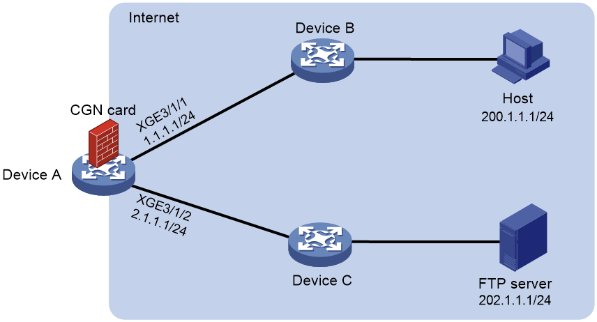
Network configuration
As shown in Figure 6, Device A acts as an egress gateway. A CGN card is installed on slot 2 of Device A, which provides address translation. For security, configure service traffic between the host and FTP server to be forwarded by Device A:
· The IP address used by the FTP server for providing services is the primary IP address of Loopback 10 on Device A.
· The source IP address of packets sent from the host to the FTP server is IP address 22.2.2.2 in NAT address group 1.
Bidirectional NAT enables the host and the FTP server to communicate with each other without perceiving each other's real IP address on the public network.
Analysis
To hide the real IP addresses of the host and FTP server on the public network, perform the following tasks:
· Configure destination address translation and set the IP address used by the FTP server for providing services to the IP address of Loopback 10.
· Configure source address translation. Configure Device A to translate the source IP address of packets sent from the host to the FTP server into the IP address in NAT address group 1.
Procedures
Configuring Device A
1. Specify IPv4 addresses for the interfaces on Device A.
<DeviceA> system-view
[DeviceA] interface ten-gigabitethernet 3/1/1
[DeviceA-Ten-GigabitEthernet3/1/1] ip address 1.1.1.1 255.255.255.0
[DeviceA-Ten-GigabitEthernet3/1/1] quit
[DeviceA] interface ten-gigabitethernet 3/1/2
[DeviceA-Ten-GigabitEthernet3/1/2] ip address 2.1.1.1 255.255.255.0
[DeviceA-Ten-GigabitEthernet3/1/2] quit
[DeviceA] interface loopback 10
[DeviceA-LoopBack10] ip address 11.1.1.1 255.255.255.0
[DeviceA-LoopBack10] quit
2. Configure an ACL:
# Configure ACL 3001 to permit all packets.
[DeviceA] acl advanced 3001
[DeviceA-acl-ipv4-adv-3001] rule 1 permit ip source any
[DeviceA-acl-ipv4-adv-3001] quit
3. Configure a failover group:
# Specify the CGN card in slot 2 as the primary node in failover group cgn1.
[DeviceA] failover group cgn1 id 1
[DeviceA-failover-group-cgn] bind slot 2 primary
[DeviceA-failover-group-cgn] quit
4. Create service instance group 1 and associate it with failover group cgn1.
[DeviceA] service-instance-group 1
[DeviceA-service-instance-group 1] failover-group cgn1
[DeviceA-service-instance-group 1] quit
5. Configure a NAT address group:
# Create address group 1 and add address 22.2.2.2 to the group.
[DeviceA] nat address-group 1
[DeviceA-address-group-1] address 22.2.2.2 22.2.2.2
[DeviceA-address-group-1] quit
6. Configure a NAT instance:
# Create a NAT instance named a with ID 1.
[DeviceA] nat instance a id 1
# Associate NAT instance a with service instance group 1.
[DeviceA-nat-instance-a] service-instance-group 1
# Configure outbound dynamic NAT to use NAT address group 1 to translate packets permitted by ACL 3001.
[DeviceA-nat-instance-a] nat outbound 3001 address-group 1
# Configure a NAT server mapping to translate packets with the primary IP address of Loopback 10 as the destination address and port 21. After address translation, the destination IP address is 202.1.1.1 and the port number is 21.
[DeviceA-nat-instance-a] nat server protocol tcp global interface loopback 10 21 inside 202.1.1.1 ftp
[DeviceA-nat-instance-a] quit
7. Configure a QoS policy to redirect traffic to the NAT instance for address translation:
# Configure traffic class a and traffic behavior a.
[DeviceA] traffic classifier a operator and
[DeviceA-classifier-a] if-match acl 3001
[DeviceA-classifier-a] quit
[DeviceA] traffic behavior cgn
[DeviceA-behavior-a] bind nat-instance a
[DeviceA-behavior-a] quit
# Create QoS policy a and associate the traffic class with the traffic behavior.
[DeviceA] qos policy a
[DeviceA-qospolicy-a] classifier a behavior a
[DeviceA-qospolicy-a] quit
# Apply the QoS policy to the inbound traffic on Ten-GigabitEthernet 3/1/1 and Ten-GigabitEthernet 3/1/2.
[DeviceA] interface ten-gigabitethernet 3/1/1
[DeviceA-Ten-GigabitEthernet3/1/1] qos apply policy a inbound
[DeviceA-Ten-GigabitEthernet3/1/1] quit
[DeviceA] interface ten-gigabitethernet 3/1/2
[DeviceA-Ten-GigabitEthernet3/1/2] qos apply policy a inbound
[DeviceA-Ten-GigabitEthernet3/1/2] quit
Configuring the host
Make sure the host and Device A can reach each other.
Verifying the configuration
# Access the FTP server by using IP address 11.1.1.1 on the host. Display NAT session information generated on Device A when Host A accesses the FTP server.
[DeviceA] display nat session verbose
Slot 3:
Initiator:
Source IP/port: 200.1.1.1/30929
Destination IP/port: 11.1.1.1/21
DS-Lite tunnel peer: -
VPN instance/VLAN ID/Inline ID: -/-/-
Protocol: TCP(6)
Inbound interface: GigabitEthernet0/0
Responder:
Source IP/port: 202.1.1.1/21
Destination IP/port: 22.2.2.2/1025
DS-Lite tunnel peer: -
VPN instance/VLAN ID/Inline ID: -/-/-
Protocol: TCP(6)
Inbound interface: GigabitEthernet0/1
State: TCP_ESTABLISHED
Application: FTP
Role: Master
Failover group ID: 1
Start time: 2023-03-07 08:20:14 TTL: 3598s
Initiator->Responder: 0 packets 0 bytes
Responder->Initiator: 0 packets 0 bytes
Total sessions found: 1
The output shows that the host (session initiator) regards the IP address of the FTP server as 11.1.1.1 and the FTP server (session responder) regards the IP address of the host as 22.2.2.2. They cannot perceive each other's real IP address on the public network.
Configuration files
Device A:
#
interface LoopBack10
ip address 11.1.1.1 255.255.255.0
#
interface Ten-GigabitEthernet3/1/1
ip address 1.1.1.1 255.255.255.0
qos apply policy a inbound
#
interface Ten-GigabitEthernet3/1/2
ip address 2.1.1.1 255.255.255.0
qos apply policy a inbound
#
acl advanced 3001
rule 1 permit ip
#
failover group cgn1 id 1
bind slot 2 primary
#
service-instance-group 1
failover-group cgn1
#
nat instance a id 1
service-instance-group 1
nat outbound 3001 address-group 1
nat server protocol tcp global interface LoopBack10 21 inside 202.1.1.1 21
#
traffic classifier a operator and
if-match acl 3001
#
traffic behavior a
bind nat-instance a
#
qos policy a
classifier a behavior a
#
nat address-group 1
address 22.2.2.2 22.2.2.2
#
Example: Configuring bidirectional NAT and NAT Server
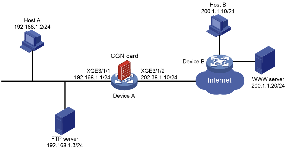
Network configuration
As shown in Figure 7, Host A accesses the Internet after NAT on Device A. A CGN card is installed on slot 2 of Device A, which provides address translation. The company uses private IP addresses on network 192.168.1.0/24 and public IP address 202.38.1.100 to provide FTP services.
Configure bidirectional NAT and NAT Server to meet the following requirements:
· Both Host A and Host B can access the FTP server by using IP address 202.38.1.100 and port 21.
· Only users on subnet 192.168.1.0/24 can access the Internet by using public IP addresses 202.38.1.2 and 202.38.1.3.
Procedures
Configuring Device A
1. Specify IPv4 addresses for the interfaces on Device A.
<DeviceA> system-view
[DeviceA] interface ten-gigabitethernet 3/1/1
[DeviceA-Ten-GigabitEthernet3/1/1] ip address 192.168.1.1 255.255.255.0
[DeviceA-Ten-GigabitEthernet3/1/1] quit
[DeviceA] interface ten-gigabitethernet 3/1/2
[DeviceA-Ten-GigabitEthernet3/1/2] ip address 202.38.1.10 255.255.255.0
[DeviceA-Ten-GigabitEthernet3/1/2] quit
2. Configure an ACL:
# Configure ACL 3002 to permit all packets.
[DeviceA] acl advanced 3002
[DeviceA-acl-ipv4-adv-3002] rule 5 permit ip source any
[DeviceA-acl-ipv4-adv-3002] quit
3. Configure a failover group:
# Specify the CGN card in slot 2 as the primary node in failover group cgn1.
[DeviceA] failover group cgn1 id 1
[DeviceA-failover-group-cgn] bind slot 2 primary
[DeviceA-failover-group-cgn] quit
4. Create service instance group 1 and associate it with failover group cgn1.
[DeviceA] service-instance-group 1
[DeviceA-service-instance-group 1] failover-group cgn1
[DeviceA-service-instance-group 1] quit
5. Configure an address group:
# Configure address group 0 and add an address range from 202.38.1.2 to 202.38.1.3.
[DeviceA] nat address-group 0
[DeviceA-address-group-0] address 202.38.1.2 202.38.1.3
[DeviceA-address-group-0] quit
6. Configure a NAT instance:
# Create a NAT instance named a with ID 1.
[DeviceA] nat instance a id 1
# Associate NAT instance a with service instance group 1.
[DeviceA-nat-instance-a] service-instance-group 1
# Configure outbound dynamic NAT to use NAT address group 0 to translate packets permitted by ACL 3002.
[DeviceA-nat-instance-a] nat outbound 3002 address-group 0
# Configure a NAT server mapping to allow external users to access the FTP server by using the address 202.38.1.100 and port 21.
[DeviceA-nat-instance-a] nat server protocol tcp global 202.38.1.100 21 inside 192.168.1.3 ftp
[Device-nat-instance-a] quit
7. Configure a QoS policy to redirect traffic to the NAT instance for address translation:
# Configure traffic class cgn and traffic behavior cgn.
[DeviceA] traffic classifier cgn operator and
[DeviceA-classifier-cgn] if-match acl 3002
[DeviceA-classifier-cgn] quit
[DeviceA] traffic behavior cgn
[DeviceA-behavior-cgn] bind nat-instance a
[DeviceA-behavior-cgn] quit
# Create QoS policy cgn and associate the traffic class with the traffic behavior.
[DeviceA] qos policy cgn
[DeviceA-qospolicy-cgn] classifier cgn behavior cgn
[DeviceA-qospolicy-cgn] quit
# Apply the QoS policy to the inbound traffic on Ten-GigabitEthernet 3/1/1.
[DeviceA] interface ten-gigabitethernet 3/1/1
[DeviceA-Ten-GigabitEthernet3/1/1] qos apply policy cgn inbound
[DeviceA-Ten-GigabitEthernet3/1/1] quit
Configuring Host B
Make sure Host B and Device A can reach each other.
Verifying the configuration
# Access the FTP server by using IP address 202.38.1.100 and port 21 on Host A. Display NAT session information generated on Device A when Host A accesses the FTP server.
[DeviceA] display nat session verbose
Slot 2:
Initiator:
Source IP/port: 192.168.1.2/22213
Destination IP/port: 202.38.1.100/21
DS-Lite tunnel peer: -
VPN instance/VLAN ID/Inline ID: -/-/-
Protocol: TCP(6)
Inbound interface: Ten-GigabitEthernet3/1/1
Responder:
Source IP/port: 192.168.1.3/21
Destination IP/port: 202.38.1.3/1024
DS-Lite tunnel peer: -
VPN instance/VLAN ID/Inline ID: -/-/-
Protocol: TCP(6)
Inbound interface: Ten-GigabitEthernet3/1/1
State: TCP_ESTABLISHED
Application: FTP
Role: Master
Failover group ID: 1
Start time: 2023-03-06 15:40:47 TTL: 3592s
Initiator->Responder: 0 packets 0 bytes
Responder->Initiator: 0 packets 0 bytes
Total sessions found: 1
# Enter the IP address of the WWW server in the address bar of the Web browser on Host A. Display NAT session information generated on Device A when Host A accesses the WWW server.
[DeviceA] display nat session verbose
Slot 2:
Initiator:
Source IP/port: 192.168.1.2/4481
Destination IP/port: 200.1.1.20/80
DS-Lite tunnel peer: -
VPN instance/VLAN ID/Inline ID: -/-/-
Protocol: TCP(6)
Inbound interface: Ten-GigabitEthernet3/1/1
Responder:
Source IP/port: 200.1.1.20/80
Destination IP/port: 202.38.1.2/1029
DS-Lite tunnel peer: -
VPN instance/VLAN ID/Inline ID: -/-/-
Protocol: TCP(6)
Inbound interface: Ten-GigabitEthernet3/1/2
State: TCP_ESTABLISHED
Application: HTTP
Role: Master
Failover group ID: 1
Start time: 2023-03-06 15:50:33 TTL: 3583s
Initiator->Responder: 0 packets 0 bytes
Responder->Initiator: 0 packets 0 bytes
Total sessions found: 1
# Access the FTP server by using IP address 202.38.1.100 and port 21 on Host B. Display NAT session information generated on Device A when Host B accesses the FTP server.
[DeviceA] display nat session verbose
Slot 2:
Initiator:
Source IP/port: 200.1.1.10/60738
Destination IP/port: 202.38.1.100/21
DS-Lite tunnel peer: -
VPN instance/VLAN ID/Inline ID: -/-/-
Protocol: TCP(6)
Inbound interface: Ten-GigabitEthernet3/1/2
Responder:
Source IP/port: 192.168.1.3/21
Destination IP/port: 200.1.1.10/60738
DS-Lite tunnel peer: -
VPN instance/VLAN ID/Inline ID: -/-/-
Protocol: TCP(6)
Inbound interface: Ten-GigabitEthernet3/1/1
State: TCP_ESTABLISHED
Application: FTP
Role: Master
Failover group ID: 1
Start time: 2023-03-06 15:55:40 TTL: 3593s
Initiator->Responder: 0 packets 0 bytes
Responder->Initiator: 0 packets 0 bytes
Total sessions found: 1
Configuration files
Device A:
#
failover group cgn1 id 1
bind slot 2 primary
#
service-instance-group 1
failover-group cgn1
#
nat instance a id 1
service-instance-group 1
nat outbound 3002 address-group 0
nat server protocol tcp global 202.38.1.100 21 inside 192.168.1.3 21
#
traffic classifier cgn operator and
if-match acl 3002
#
traffic behavior cgn
bind nat-instance a
#
qos policy cgn
classifier cgn behavior cgn
#
interface Ten-GigabitEthernet3/1/1
ip address 192.168.1.1 255.255.255.0
qos apply policy cgn inbound
#
interface Ten-GigabitEthernet3/1/2
ip address 202.38.1.10 255.255.255.0
#
nat address-group 0
address 202.38.1.2 202.38.1.3
#
acl advanced 3002
rule 5 permit ip
Example: Configuring internal users to use different traffic redirection policies and different NAT address groups to access the external network
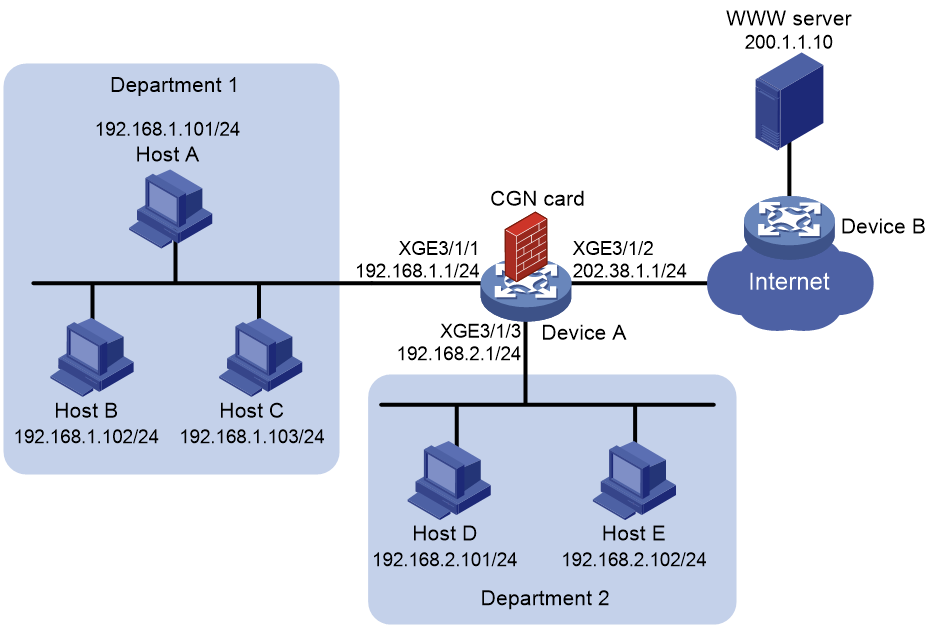
Network configuration
As shown in Figure 8, the hosts access the Internet after NAT on Device A. A CGN card is installed on slot 2 of Device A, which provides address translation. Department 1 uses private network 192.168.1.0/24 and Department 2 uses private network 192.168.2.0/24.
Configure outbound NAT to meet the following requirements:
· Department 1 uses IP addresses in address range 202.38.1.100 to 202.38.1.200 to access the Internet and NO-PAT is used for address translation. A NAT address can be assigned to only one private IP address for address translation at the same time.
· Department 2 uses IP addresses in address range 202.38.1.2 to 202.38.1.5 to access the Internet and PAT is used for address translation. A NAT address can be assigned to multiple private IP addresses for address translation at the same time.
Procedures
Configuring Device A
1. Specify IPv4 addresses for the interfaces on Device A.
<DeviceA> system-view
[DeviceA] interface ten-gigabitethernet 3/1/1
[DeviceA-Ten-GigabitEthernet3/1/1] ip address 192.168.1.1 255.255.255.0
[DeviceA-Ten-GigabitEthernet3/1/1] quit
[DeviceA] interface ten-gigabitethernet 3/1/2
[DeviceA-Ten-GigabitEthernet3/1/2] ip address 202.38.1.1 255.255.255.0
[DeviceA-Ten-GigabitEthernet3/1/2] quit
[DeviceA] interface ten-gigabitethernet 3/1/3
[DeviceA-Ten-GigabitEthernet3/1/3] ip address 192.168.2.1 255.255.255.0
[DeviceA-Ten-GigabitEthernet3/1/3] quit
2. Configure a failover group:
# Specify the CGN card in slot 2 as the primary node in failover group cgn1.
[DeviceA] failover group cgn1 id 1
[DeviceA-failover-group-cgn] bind slot 2 primary
[DeviceA-failover-group-cgn] quit
3. # Create service instance group 1 and associate it with failover group cgn1.
[DeviceA] service-instance-group 1
[DeviceA-service-instance-group 1] failover-group cgn1
[DeviceA-service-instance-group 1] quit
4. Configure global NAT:
a. Configure an ACL:
# Configure ACL 3000 to identify packets from subnet 192.168.1.0/24.
[DeviceA] acl advanced 3000
[DeviceA-acl-ipv4-adv-3000] rule 5 permit ip source 192.168.1.0 0.0.0.255
[DeviceA-acl-ipv4-adv-3000] quit
# Configure ACL 3001 to identify packets from subnet 192.168.2.0/24.
[DeviceA] acl advanced 3001
[DeviceA-acl-ipv4-adv-3001] rule 5 permit ip source 192.168.2.0 0.0.0.255
[DeviceA-acl-ipv4-adv-3001] quit
b. Configure an address group:
# Configure address group 0 and add an address range from 202.38.1.100 to 202.38.1.200.
[DeviceA] nat address-group 0
[DeviceA-address-group-0] address 202.38.1.100 202.38.1.200
[DeviceA-address-group-0] quit
# Configure address group 1 and add an address range from 202.38.1.2 to 202.38.1.5.
[DeviceA] nat address-group 1
[DeviceA-address-group-1] address 202.38.1.2 202.38.1.5
[DeviceA-address-group-1] quit
c. Configure a NAT instance:
# Create a NAT instance named a with ID 1.
[DeviceA] nat instance a id 1
# Associate NAT instance a with service instance group 1.
[DeviceA-nat-instance-a] service-instance-group 1
# Configure an outbound NO-PAT rule to translate the source addresses of outgoing packets permitted by ACL 3000 into the addresses in address group 0.
[DeviceA-nat-instance-a] nat outbound 3000 address-group 0 no-pat
# Configure an outbound PAT rule to translate the source addresses of outgoing packets permitted by ACL 3001 into the addresses in address group 1.
[DeviceA-nat-instance-a] nat outbound 3001 address-group 1
[Device-nat-instance-a] quit
5. Configure a QoS policy to redirect traffic to the NAT instance for address translation:
# Configure traffic class cgn and traffic behavior cgn.
[DeviceA] traffic classifier cgn operator or
[DeviceA-classifier-cgn] if-match acl 3000
[DeviceA-classifier-cgn] if-match acl 3001
[DeviceA-classifier-cgn] quit
[DeviceA] traffic behavior cgn
[DeviceA-behavior-cgn] bind nat-instance a
[DeviceA-behavior-cgn] quit
# Create QoS policy cgn and associate the traffic class with the traffic behavior.
[DeviceA] qos policy cgn
[DeviceA-qospolicy-cgn] classifier cgn behavior cgn
[DeviceA-qospolicy-cgn] quit
# Apply the QoS policy to the inbound traffic on Ten-GigabitEthernet 3/1/1.
[DeviceA] interface ten-gigabitethernet 3/1/1
[DeviceA-Ten-GigabitEthernet3/1/1] qos apply policy cgn inbound
[DeviceA-Ten-GigabitEthernet3/1/1] quit
# Apply the QoS policy to the inbound traffic on Ten-GigabitEthernet 3/1/3.
[DeviceA] interface ten-gigabitethernet 3/1/3
[DeviceA-Ten-GigabitEthernet3/1/3] qos apply policy cgn inbound
[DeviceA-Ten-GigabitEthernet3/1/3] quit
Configuring hosts
Make sure each host and Device A can reach each other.
Verifying the configuration
# Enter the IP address of the WWW server in the address bar of the Web browser on Host A. Display NAT session information generated on Device A when Host A accesses the WWW server.
[DeviceA] display nat session verbose
Slot 2:
Initiator:
Source IP/port: 192.168.1.101/4481
Destination IP/port: 200.1.1.10/80
DS-Lite tunnel peer: -
VPN instance/VLAN ID/Inline ID: -/-/-
Protocol: TCP(6)
Inbound interface: Ten-GigabitEthernet3/1/1
Responder:
Source IP/port: 200.1.1.10/80
Destination IP/port: 202.38.1.2/1029
DS-Lite tunnel peer: -
VPN instance/VLAN ID/Inline ID: -/-/-
Protocol: TCP(6)
Inbound interface: Ten-GigabitEthernet3/1/2
State: TCP_ESTABLISHED
Application: HTTP
Role: Master
Failover group ID: 1
Start time: 2023-02-13 15:50:33 TTL: 3583s
Initiator->Responder: 0 packets 0 bytes
Responder->Initiator: 0 packets 0 bytes
Total sessions found: 1
# Display information about NAT NO-PAT entries generated on Device A when Host A accesses the WWW server.
[DeviceA] display nat no-pat
Slot 2:
Local IP: 192.168.1.101
Global IP: 202.38.1.2
Reversible: N
Type : Outbound
Total entries found: 1
# Enter the IP address of the WWW server in the address bar of the Web browser on Host D. Display NAT session information generated on Device A when Host D accesses the WWW server.
[DeviceA] display nat session verbose
Slot 2:
Initiator:
Source IP/port: 192.168.2.101/33283
Destination IP/port: 200.1.1.10/80
DS-Lite tunnel peer: -
VPN instance/VLAN ID/Inline ID: -/-/-
Protocol: TCP(6)
Inbound interface: Ten-GigabitEthernet3/1/3
Responder:
Source IP/port: 200.1.1.10/80
Destination IP/port: 202.38.1.188/1026
DS-Lite tunnel peer: -
VPN instance/VLAN ID/Inline ID: -/-/-
Protocol: TCP(6)
Inbound interface: Ten-GigabitEthernet3/1/2
State: TCP_ESTABLISHED
Application: HTTP
Role: Master
Failover group ID: 1
Start time: 2023-02-13 15:54:16 TTL: 3588s
Initiator->Responder: 0 packets 0 bytes
Responder->Initiator: 0 packets 0 bytes
Total sessions found: 1
Configuration files
Device A:
#
failover group cgn1 id 1
bind slot 2 primary
#
service-instance-group 1
failover-group cgn1
#
nat instance a id 1
service-instance-group 1
nat outbound 3000 address-group 0 no-pat
nat outbound 3001 address-group 1
#
traffic classifier cgn operator or
if-match acl 3000
if-match acl 3001
#
traffic behavior cgn
bind nat-instance a
#
qos policy cgn
classifier cgn behavior cgn
#
interface Ten-GigabitEthernet3/1/1
ip address 192.168.1.1 255.255.255.0
qos apply policy cgn inbound
#
interface Ten-GigabitEthernet3/1/2
ip address 202.38.1.1 255.255.255.0
#
interface Ten-GigabitEthernet3/1/3
ip address 192.168.2.1 255.255.255.0
qos apply policy cgn inbound
#
nat address-group 0
address 202.38.1.2 202.38.1.5
#
nat address-group 1
address 202.38.1.100 202.38.1.200
#
acl advanced 3000
rule 5 permit ip source 192.168.1.0 0.0.0.255
#
acl advanced 3001
rule 5 permit ip source 192.168.2.0 0.0.0.255
#
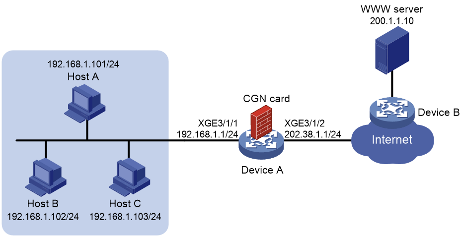
Example: Configuring internal users to access external Web servers by using NAT addresses
Network configuration
As shown in Figure 6, the hosts access the Internet after NAT on Device A. A CGN card is installed on slot 2 of Device A, which provides address translation. The company uses private IP addresses on network 192.168.1.0/24 and public IP addresses 202.38.1.2 and 202.38.1.3.
Configure outbound NAT to meet the following requirements:
· Only hosts on subnet 192.168.1.0/24 can access the Internet.
· Device A performs many-to-many address translation.
Figure 9 Network diagram
Procedures
Configuring Device A
1. Specify IPv4 addresses for the interfaces on Device A.
<DeviceA> system-view
[DeviceA] interface ten-gigabitethernet 3/1/1
[DeviceA-Ten-GigabitEthernet3/1/1] ip address 192.168.1.1 255.255.255.0
[DeviceA-Ten-GigabitEthernet3/1/1] quit
[DeviceA] interface ten-gigabitethernet 3/1/2
[DeviceA-Ten-GigabitEthernet3/1/2] ip address 202.38.1.1 255.255.255.0
[DeviceA-Ten-GigabitEthernet3/1/2] quit
2. Configure a failover group:
# Specify the CGN card in slot 2 as the primary node in failover group cgn1.
[DeviceA] failover group cgn1 id 1
[DeviceA-failover-group-cgn] bind slot 2 primary
[DeviceA-failover-group-cgn] quit
3. Create service instance group 1 and associate it with failover group cgn1.
[DeviceA] service-instance-group 1
[DeviceA-service-instance-group 1] failover-group cgn1
[DeviceA-service-instance-group 1] quit
4. Configure global NAT:
a. Configure an ACL:
# Configure ACL 3000 to identify packets from subnet 192.168.1.0/24.
[DeviceA] acl advanced 3000
[DeviceA-acl-ipv4-adv-3000] rule 5 permit ip source 192.168.1.0 0.0.0.255
[DeviceA-acl-ipv4-adv-3000] quit
b. Configure an address group:
# Configure address group 0 and add an address range from 202.38.1.2 to 202.38.1.3.
[DeviceA] nat address-group 0
[DeviceA-address-group-0] address 202.38.1.2 202.38.1.3
[DeviceA-address-group-0] quit
c. Configure a NAT instance:
# Create a NAT instance named a with ID 1.
[DeviceA] nat instance a id 1
# Associate NAT instance a with service instance group 1.
[DeviceA-nat-instance-a] service-instance-group 1
# Configure outbound dynamic NAT to use NAT address group 0 to translate packets permitted by ACL 3000.
[DeviceA-nat-instance-a] nat outbound 3000 address-group 0
[DeviceA-nat-instance-a] quit
5. Configure a QoS policy to redirect traffic to the NAT instance for address translation:
# Configure traffic class cgn and traffic behavior cgn.
[DeviceA] traffic classifier cgn operator and
[DeviceA-classifier-cgn] if-match acl 3000
[DeviceA-classifier-cgn] quit
[DeviceA] traffic behavior cgn
[DeviceA-behavior-cgn] bind nat-instance a
[DeviceA-behavior-cgn] quit
# Create QoS policy cgn and associate the traffic class with the traffic behavior.
[DeviceA] qos policy cgn
[DeviceA-qospolicy-cgn] classifier cgn behavior cgn
[DeviceA-qospolicy-cgn] quit
# Apply the QoS policy to the inbound traffic on Ten-GigabitEthernet 3/1/1.
[DeviceA] interface ten-gigabitethernet 3/1/1
[DeviceA-Ten-GigabitEthernet3/1/1] qos apply policy cgn inbound
[DeviceA-Ten-GigabitEthernet3/1/1] quit
Configuring hosts
Make sure each host and Device A can reach each other.
Verifying the configuration
# Enter the IP address of the WWW server in the address bar of the Web browser on Host A. Display NAT session information generated on Device A when Host A accesses the WWW server.
[DeviceA] display nat session verbose
Slot 2:
Initiator:
Source IP/port: 192.168.1.101/4481
Destination IP/port: 200.1.1.10/80
DS-Lite tunnel peer: -
VPN instance/VLAN ID/Inline ID: -/-/-
Protocol: TCP(6)
Inbound interface: Ten-GigabitEthernet3/1/1
Responder:
Source IP/port: 200.1.1.10/80
Destination IP/port: 202.38.1.2/1029
DS-Lite tunnel peer: -
VPN instance/VLAN ID/Inline ID: -/-/-
Protocol: TCP(6)
Inbound interface: Ten-GigabitEthernet3/1/2
State: TCP_ESTABLISHED
Application: HTTP
Role: Master
Failover group ID: 1
Start time: 2023-02-05 16:15:28 TTL: 3591s
Initiator->Responder: 0 packets 0 bytes
Responder->Initiator: 0 packets 0 bytes
Total sessions found: 1
Configuration files
Device A:
#
failover group cgn1 id 1
bind slot 2 primary
#
service-instance-group 1
failover-group cgn1
#
nat instance a id 1
service-instance-group 1
nat outbound 3000 address-group 0
#
traffic classifier cgn operator and
if-match acl 3000
#
traffic behavior cgn
bind nat-instance a
#
qos policy cgn
classifier cgn behavior cgn
#
interface Ten-GigabitEthernet3/1/1
ip address 192.168.1.1 255.255.255.0
qos apply policy cgn inbound
#
interface Ten-GigabitEthernet3/1/2
ip address 202.38.1.1 255.255.255.0
#
nat address-group 0
address 202.38.1.2 202.38.1.3
#
acl advanced 3000
rule 5 permit ip source 192.168.1.0 0.0.0.255
#
Related documentation
· H3C CR16000-F Routers NAT Configuration Guide
· H3C CR16000-F Routers NAT Command Reference
