- Table of Contents
-
- H3C S9500 Series Routing Switches Installation Manual-(V2.03)
- 00-1Cover
- 01-Chapter1 Product Overview
- 02-Chapter2 Preparing for Installation
- 03-Chapter3 Installing the Switch
- 04-Chapter4 Commissioning the Switch
- 05-Chapter5 Troubleshooting and Maintaining the Switch
- 06-Appendix A Cable Management
- 07-Appendix B Engineering Labels for Cables
- 08-Appendix C Installation of Lightning Arrester for AC Power
- Related Documents
-
| Title | Size | Download |
|---|---|---|
| 07-Appendix B Engineering Labels for Cables | 138 KB |
Appendix B Engineering Labels for Cables
B.1.6 Information Carried on Labels
B.2 Engineering Labels for Ethernet Cables
B.3 Engineering Labels for Optical Fibers
B.3.1 Labels for the Fiber that Connects Two Devices
B.3.2 Labels for the Fiber that Connects the Device and the ODF
B.4 Engineering Labels for Power Cables
B.4.1 Labels for DC Power Cables
B.4.2 Labels for AC Power Cables
Appendix B Engineering Labels for Cables
Engineering labels are affixed to both ends of the various cables to identify the physical positions of cables on different devices. Labels on the cables facilitate correct and orderly connection of cables, and easy maintenance after the installation.
There are two types of engineering labels, specialized for the power cables and signal cables respectively. The power cables include the AC power cables and DC power cables (excluding the power cable that connects the distribution box and the cabinet). The signal cables include external cables of alarm box, Ethernet cables, optical fibers, trunk cables and subscriber cables (excluding the antenna feeders).
& Note:
In case there is special requirement from the user of the equipment on the description method of the labels, the labels should be printed accordingly. However, this must be stated in the self-check report.
B.1 Introduction to Labels
B.1.1 Material
l Material: Polyester (PET), with UL and CSA certifications
l Color: chalk white
l Thickness: 0.09mm
l Ambient temperature: -29~149 degrees Celsius
l Laser printing or handwriting with oiliness markers
B.1.2 Type and Shape
There are two types of engineering labels for power cables and signal cables respectively.
I. Label for signal cables
The label for signal cables is L-shaped with fixed dimensions, as shown in Figure B-1 (expressed in mm).

|
(1) Dividing line |
(2) Cut dotted line |
Figure B-1 Label for signal cables
The dividing lines on the label help to specify more clearly the position of a cable. For example, there is one between the cabinet number and the frame number and another one between the frame number and the slot number. The dividing line is 1.5mm´0.6mm in size with the color of PONTONE 656c (light blue).
The cut dotted line helps to fold the label when affixing it to the cable, and its size is 1.0mm´2.0mm.
There is a mark “TO:” (upside down in the figure) at the lower right corner of the label. The mark is used to identify the opposite end of the cable on which the label is affixed.
II. Label for power cables
The label for power cables should be attached to the identification plate on the cable ties that are bundled to the cable. The identification plate has an embossment of 0.2mm´0.6mm around (symmetric on both sides), and the area in the middle is for affixing the label, as shown in Figure B-2 (expressed in mm):

|
(1) Cable tie |
(2) Label |
(3) Dividing line on the label |
Figure B-2 Label for power cables
B.1.3 Printing Labels
The contents can be printed or written on the labels. Printing is recommended for the sake of high efficiency and eye-pleasant layout.
I. Template for the printing
The Word-form template is available for label printout. You can get the template from H3C local office.
When using the template, you can directly modify the contents on the template, and the following should be observed:
l The settings of centered characters, direction, and fonts should not be changed.
l When there are too many characters to be filled in, zoom out the characters, but make sure the printouts are clear and legible.
II. Cells merging on the template
To merge the cells, you should first recover the table structure (if gridlines are displayed, you can start from Step 3 directly).
1) Select the menu item [Edit/Select All].
2) Select the menu item [Format/Borders and Shading/Borders]. Select Box and click <OK>.
3) Drag the mouse to select the cells to be merged and select the menu item [Table/Merge Cells].
If two merged cells are still not enough to accommodate the characters, use multiple lines.
III. Requirements on the printer
To print the labels, laser jet printer must be used, although there is no restriction on the model of the printer. Before printing the label, set up the page and try the printing on ordinary blank paper (both sides are blank):
1) Cover the blank paper onto the whole page of label paper, and check whether the page setup conforms to the requirement.
2) Make sure the printer properties, such as "paper size" and “direction”, have been set correctly.
3) If the warning prompt as shown in Figure B-3 appears before printing, click <Ignore> to continue the printing.
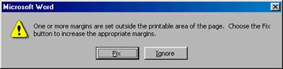
Figure B-3 Warning prompt before printing
If the printout conforms to the requirement, print it to label paper. If the printout does not conform, adjust the page setup and try the printing again, until the correct printout is produced. The method of adjusting the page setup is as follows:
1) Select the menu item [File/Page Setup].
2) Select the Margins tab page.
3) Select Left for Gutter Position.
4) Set Header and Footer as 0, and adjust the values of Top, Bottom, Left, and Right.
After the page setup has been made correct, save it for future use. This page setup is only necessary in the first time you use the template to print the labels.
IV. Requirements on feeding the printer
Different from the ordinary paper, the label paper is composed of two pages. No matter what model of printer you are using, feed in the labels one after another by hand. Never use the auto-feed mode in order to avoid jamming the labels. Different models of printers may have different feeding modes, make sure to feed in the labels correctly.
V. Requirements on the printed label
Make sure the printed label satisfy the following requirements:
l All the printouts must be on the label, and nothing should be printed on the bottom page of the label.
l Contents in the cells should be aligned in the center. In a single-line printout, the dividing lines and the mark “TO” should not be covered by the printed characters.
l When the cells are merged and the printouts are made in multiple lines, avoid covering the mark “TO” when printing the texts by using the space bar to move the printing contents to the next line.
B.1.4 Writing Labels
Use the black oiliness markers to write the labels.
In special cases, black ball-pens are allowed, although not recommended. When writing with the ball-pen, take care not to leave the oil on the label, which may contaminate the label and blur the words..
& Note:
The delivered marker has two nibs. Make sure to use the smaller nib to write the labels.
For the sake of easy recognition and good looking, the font in handwriting should be close to the standard typeface as much as possible. Table B-1 shows the standard typeface.
Table B-1 Standard typeface for handwriting
|
0 |
1 |
2 |
3 |
4 |
5 |
6 |
7 |
8 |
|
9 |
A |
B |
C |
D |
E |
F |
G |
H |
|
I |
J |
K |
L |
M |
N |
O |
P |
Q |
|
R |
S |
T |
U |
V |
W |
X |
Y |
Z |
Write the characters in proper size, and the direction is as shown in Figure B-4:

Figure B-4 Writing direction of the label
B.1.5 Affixing Labels
After printing or writing the label, remove the label from the bottom page and affix it to the signal cable, or the identification plate of the power cable.
I. Affixing the label to the signal cable
The steps to affix the label to the cable are shown in Figure B-5, Figure B-6 and Figure B-7. The finished labels should be on the right or top of the cables, according to different cabling methods. The left part of the figures shows the method to affix the label when the cable is laid vertically, while the right part of the figures shows the method to affix the label when the cable is laid horizontally.
The label is affixed 2cm from the connector on the signal cable. In special cases, for example, to avoid cable bent or affecting other cables, other positions are allowed to affix the labels.
1) Stick the label to the proper position on the cable, fold the narrow part of the label according to the directions shown in Figure B-5.

Figure B-5 Stick the label onto proper position of the signal cable
The length of the narrow part is based on an external cable diameter of 2.6mm, after this part has been stuck to the back of the label, it may not overlap the entire printed part.
2) Fold the printed part along the dotted line according to the directions shown in Figure B-6.

3) After the printed part of the label has been folded up, the narrow part of the label should be covered completely, as shown in Figure B-7.

Figure B-7 Appearance of affixed labels on signal cables
II. Affixing the label to the power cable
Remove the label from the bottom page, then affix it to the identification plate on the cable tie. The label should be stuck to the rectangular flute, and should be stuck to only one side of the identification plate. Make sure to affix the labels on the same side of the identification plates. The cable ties are bundled at 2cm from the connectors, and other positions are allowed in special circumstances.
Cable ties should be bundled on both ends of a cable. After the bundling, the finished identification plate should be on top of the cable in horizontal cabling, or on the right side of the cable in vertical cabling. Make sure the label is facing out, as shown in Figure B-8.

Figure B-8 Appearance of affixed labels on power cables
B.1.6 Information Carried on Labels
I. For power cables
Labels for power cables are only affixed on one side of the identification plates. On the labels, there is information (the part after the mark “TO:”) about the location of the device on the other end of the cable, like the location of control cabinet, distribution box or power socket.
II. For signal cables
The two sides of the label affixed on the signal cable carry information about the location of the ports connected to both ends of the cable, as shown in Figure B-9.
The information is given like this:
l Area 1 contains the location information of local end of the cable.
l Area 2 (with the mark "TO:") contains the location information of the opposite end of the cable.
l Area 3 has been folded up inside the label.

Figure B-9 Printed parts on the label for signal cables
Seen from the cabling end of the equipment, the text part of the label is on the right side of the cable. The side with “TO:” that is facing outside carries the location information of the opposite end; and the other side carries the location information of the local end. Therefore, the information in Area 1 at one end is the same as the information in Area 2 at the other end of the cable, and vice versa. In other words, the local information at one end is called the opposite information at the other end.
B.1.7 Remarks
l When printing/writing and affixing labels, pay attention to keep the labels clean.
l Since the label paper is made of moistureproof and waterproof material, ink-jet printers and ink pens are forbidden for printing and writing labels.
l Labels should be affixed with good order in alignment.
l Cable ties should be bundled in the same position of power cables, with identification plates on the same side.
l The positions of “up”, “down”, “right” or “left” are all based on the viewpoint of the engineering person who is working on the label.
B.2 Engineering Labels for Ethernet Cables
These labels are affixed to the Ethernet cables that connect the boards in the frames, or on the cables that connect HUBs and servers or agents of the Value Added Service (VAS) products.
I. Meaning of the Label
Table B-2 shows the information on both sides of the labels affixed to the Ethernet cables that connect the boards in the frames.
Table B-2 Information on labels affixed to the Ethernet cables
|
Content |
Meaning |
Example |
|
MN-B-C-D |
MN: Cabinet number |
For example, A01 |
|
B: Frame number |
Numbered in top-down order with two digits, for example, 01 |
|
|
C: Physical slot number |
Numbered in top-down and left-right order with two digits, for example, 01 |
|
|
D: Ethernet port number |
Numbered in top-down and left-right order with two digits, for example, 01 |
|
|
MN-Z |
MN: Cabinet number |
For example, B02 |
|
Z: Location number |
Valid location number of the terminal device onsite. If the cable is connected to a router in a cabinet, the serial numbers of the cabinet, the frame and the Ethernet interface of the router should be specified, for example, B02-03-12. If the cable is connected to the Network Management Station (NMS), specific location of the NMS should be given. |
In VAS products, the information provided on the labels is different, subject to different devices that the Ethernet cables are connecting.
l Labels for the Ethernet cable that connects the HUB and the server
1) The label on the HUB end should indicate the number of the frame and cabinet where the HUB locates, and the serial number on the HUB.
2) The label on the server end should indicate the number of the frame and cabinet where the server locates. In case it is a stand-alone server, specific position of the server should be provided.
l Labels for the Ethernet cable that connects the HUB and the agent
1) The label on the agent end should contain the serial number of the Ethernet port. The definitions of the cabinet number and frame number are the same as those described in Table B-2 above.
2) If it is a stand-alone HUB without any cabinet or frame, the label should contain specific location information that identifies the HUB.
3) The serial number on the HUB, the network port number of the agent and the location of stand-alone server should be specified according to actual connection.
II. Example of the Label
Figure B-10 shows the label on the Ethernet cable:

Figure B-10 Example of the label on the Ethernet cable
“A01-03-10-05” indicates that on the local end of the Ethernet cable is connected with Ethernet Port 05, Slot 10, Frame 03 of the cabinet on Row A, Column 01 in the machine room.
“B02-03-12” indicates that the opposite end of the Ethernet cable is connected with Ethernet Port 12, Frame 03 of the cabinet on Row B, Column 02 in the machine room.
B.3 Engineering Labels for Optical Fibers
These labels are affixed to the optical fibers that connect the optical interfaces on the boards in a frame, or on the device boxes. There are two types of labels for optical fibers: one is for the fiber that connects the optical interfaces on two devices, the other is for the fiber that connects the device and the Optical Distribution Frame (ODF).
B.3.1 Labels for the Fiber that Connects Two Devices
I. Meaning of the label
Table B-3 shows the information on both sides of the labels affixed to the optical fiber that connects two devices.
Table B-3 Information on labels affixed to the fiber between two devices
|
Content |
Meaning |
Example |
|
MN-B-C-D-R/T |
MN: cabinet number |
For example, A01 |
|
B: frame number |
Numbered in top-down order with two digits, for example, 01 |
|
|
C: physical slot number |
Numbered in top-down and left-right order with two digits, for example, 01 |
|
|
D: optical interface number |
Numbered in top-down and left-right order with two digits, for example, 05 |
|
|
R: optical receiving interface T: optical transmitting interface |
— |
|
|
MN-B-C-D-R/T |
MN: cabinet number |
The meanings are the same as above. When the local device and the opposite end device are not in the same machine room, MN can be the name of the machine room. |
|
B: frame number |
||
|
C: physical slot number |
||
|
D: optical interface number |
||
|
R: optical receiving interface T: optical transmitting interface |
— |
II. Example of the label
Figure B-11 shows the label on the optical fiber between two devices:

Figure B-11 Example of the label on the optical fiber between two devices
“A01-01-05-05-R” indicates that the local end of the optical fiber is connected with Optical Receiving Interface 05 on Slot 5, Frame 01 in the cabinet on Row A, Column 01 in the machine room.
“G01-01-01-01-T” indicates that the opposite end of the optical fiber is connected with Optical Transmitting Interface 01 on Slot 01, Frame 01 in the cabinet on Row G, Column 01 in the machine room
B.3.2 Labels for the Fiber that Connects the Device and the ODF
I. Meaning of the label
Table B-4 shows the information on both sides of the labels affixed to the optical fiber that connects the device and the ODF.
Table B-4 Information on labels affixed to the fiber between the device and the ODF
|
Content |
Meaning |
Example |
|
MN-B-C-D-R/T |
MN: cabinet number |
For example, A01 |
|
B: frame number |
Numbered in bottom-up order with two digits, for example, 01 |
|
|
C: physical slot number |
Numbered in top-down and left-right order with two digits, for example, 01. |
|
|
D: optical interface number |
Numbered in top-down and left-right order with two digits, for example, 05 |
|
|
R: optical receiving interface T: optical transmitting interface |
— |
|
|
ODF-MN-B-C-R/T |
MN: row number and column number of ODF |
Numbered in the same rule as that of the cabinets, for example, G01 is the ODF of Row G and Column 01 |
|
B: row number of the terminal device |
Range from 01 to 99, for example, 01-01 |
|
|
C: column number of the terminal device |
||
|
R: optical receiving interface T: optical transmitting interface |
— |
II. Example of the label
Figure B-12 shows the label on the optical fiber between the device and the ODF.

Figure B-12 Example of the label on the optical fiber between the device and the ODF
“ODF-G01-01-01-R” indicates that the local end of the optical fiber is connected with the optical receiving terminal on Row 01, Column 01 of the ODF in Row G Column 01 in the machine room.
“A01-01-05-05-R” indicates that the opposite end of the optical fiber is connected with Optical Receiving Interface 5 on Slot 05, frame 01 in the cabinet on Row A, Column 01 in the machine room.
B.4 Engineering Labels for Power Cables
B.4.1 Labels for DC Power Cables
The labels are affixed to the DC cables that provide power for the cabinets, and the protection grounding cables, including the -48V, PGND, and BGND cables. The labels for DC power cables are affixed to one side of the identification plates on cable ties.
I. Meaning of the label
Table B-5 shows the information carried on the labels for the DC power cables:
Table B-5 Information on labels affixed to the DC power cables
|
Content |
Meaning |
|
MN(BC)--48V1 |
MN(BC): BC is written right under MN. On the loaded cabinet side, only MN is used to identify the cabinet. On the power cabinet side, MN identifies the row and column number of the power distribution equipment like the control cabinet and distribution box, BC identifies the row and column number of the -48V connecter (if there is no row number or column number, or the connecter can be identified without them, BC can be omitted). BGND and PGND have no row and column number for identification. |
|
MN(BC)--48V2 |
|
|
MN(BC)-BGND |
|
|
MN(BC)-PGND |
The label only carries location information about the opposite equipment, the control cabinet or the distribution box, while information of the local end is not necessary. Table B-5 lists the information of two -48V power supplies on the label. The information for other DC voltages (such as 24V, 60V) should be given in similar methods.
II. Example of the label
Make sure that labels are affixed in correction direction. That is, after the cable ties are bundled onto the cable, the identification plates with the labels should face up, and the text on the labels in the same cabinet should be in the same direction, as shown in Figure B-13.

Figure B-13 Example of the labels on the DC power cable
In Figure B-13, (1) indicates the label on the loaded cabinet side, which carries the information about the position of the cable on the power distribution box. (2) indicates the label on the distribution box side, which carries the information about the position of the cable on the loaded cabinet side.
On the loaded cabinet side, the label marked with “A01/B08--48V2” on the cable indicates that the cable is -48V2 DC supply, which is from the 8th connecter on the second row of -48V bus bar in the cabinet on Row A, and Column 1 in the machine room.
On the distribution box side, the label marked with “B03--48V2” indicates that the cable is -48V2 DC supply, which is from the loaded cabinet on Row B, Column 03 in the machine room.
& Note:
l In the power distribution box (or the first power cabinet of a row in the transmission machine room), every terminal block on the -48V connector bar has a numeric identification. For example, in the above label of “A01/B08--48V2”, “08” (or sometimes “8”) is the numeric identification of the terminal block.
l PGND and BGND are two copper bars, on which the terminal blocks are short-circuited, therefore which terminal is connected makes no difference. It is only necessary to give the row and column of the power distribution box, instead of giving the specific serial number of the terminal block on the copper bar. For example, if the label on the loaded cabinet side is “A01-BGND”, it means that the power cable is a BGND that connects BGND copper bar in the power distribution box on Row A, Column 01 in the machine room. Information on the labels for PGND cables should be given in the similar way.
B.4.2 Labels for AC Power Cables
The labels are affixed to the AC cables that provide power for the cabinets, and the protection grounding cables, including the POWER, PGND, and BGND cables. The 220V AC cables and related PGND and BGND cables are covered with insulating sheath, so the labels only need to contain the words of “AC" and the cabinet number. The labels for AC power cables are affixed to one side of the identification plates on cable ties.
I. Meaning of the label
Table B-6 shows the information carried on the labels for the AC power cables.
Table B-6 Information on labels affixed to the AC power cables
|
Content |
Meaning |
|
MN-AC |
MN: serial number of the cabinet or the socket where the power is led in The location of the socket is marked out according to onsite situation. If the sockets can be identified by row number and column number, they can be numbered following the same rule for the cabinets. If the sockets cannot be identified by rows and columns, specify the detailed locations to avoid confusing with other sockets. |
The label only carries location information about the opposite equipment and the power socket, while information of the local end is not necessary.
II. Example of the label
Make sure that labels are affixed in correction direction. That is, after the cable ties are bundled onto the cable, the identification plates with the labels should face up, and the text on the labels in the same cabinet should be in the same direction, as shown in Figure B-14:

Figure B-14 Example of the labels on the AC power cable
In Figure B-14, (1) indicates the label on the loaded cabinet side, which carries the information about the position of the cable on the power socket. (2) indicates the label on the power socket side, which carries the information about the position of the cable on the loaded cabinet side.
On the loaded cabinet side, the label marked with “A01-AC” indicates that the power cable is connected to the socket of Row A and Column 01 in the machine room.
On the power socket side, the label marked with “B01-AC” indicates that the power cable is connected to the loaded cabinet of Row B, Column 01 in the machine room.