- Table of Contents
-
- H3C S9500 Series Routing Switches Installation Manual-(V2.03)
- 00-1Cover
- 01-Chapter1 Product Overview
- 02-Chapter2 Preparing for Installation
- 03-Chapter3 Installing the Switch
- 04-Chapter4 Commissioning the Switch
- 05-Chapter5 Troubleshooting and Maintaining the Switch
- 06-Appendix A Cable Management
- 07-Appendix B Engineering Labels for Cables
- 08-Appendix C Installation of Lightning Arrester for AC Power
- Related Documents
-
| Title | Size | Download |
|---|---|---|
| 05-Chapter5 Troubleshooting and Maintaining the Switch | 2 MB |
Chapter 5 Troubleshooting and Maintaining the Switch
5.1 Troubleshooting the Switch
5.1.1 Troubleshooting the Console Terminal
5.1.3 Troubleshooting the Fan Tray(s)
5.2.2 Replacing and Cleaning the PSU Air Filter
5.2.3 Replacing and Cleaning the Chassis Air Filter
5.2.4 Replacing and Installing a Card
5.3.1 Recommended Upgrade Procedure
5.3.2 Local Loading through Boot Menu
5.3.3 Local or Remote Loading through CLI
5.3.4 Troubleshooting Software Upgrade
Chapter 5 Troubleshooting and Maintaining the Switch
5.1 Troubleshooting the Switch
Although the S9500 series have undergone a comprehensive and strict factory test before delivery, there might be some fault occurring due to improper installation and initial configuration. This chapter describes how to troubleshoot the S9500 series.
5.1.1 Troubleshooting the Console Terminal
If the system is normal after the Switch is powered on, the booting information will be displayed on the Console terminal. If the configuration system has failed, the Console terminal may give illegible output or nothing at all.
I. The terminal gives no displays after the Switch is powered on
In this case, you should check whether:
l The power system is working normally.
l The SRPU is working normally.
l The Console cable has been connected to the Console port on the SRPU.
If no problem has been found in the above checking, the symptom is very likely to be caused by the errors listed below.
l The Console cable is not connected to the right serial port, that is, the port in use is not the one configured on the terminal.
l There are Console terminal parameter errors. (According to the parameter setting requirements, you should set the baud rate to 9600, data bits to 8, parity to None, stop bits to 1, flow control to None, and select VT100 as terminal emulation.)
l The Console cable is not in good condition.
II. The terminal gives illegible characters.
This symptom is very likely caused by a Console terminal setting error. In this case, check that you have set the baud rate to 9600, data bits to 8, parity to None, stop bits to 1, flow control to None, and select VT100 as terminal emulation.
5.1.2 Troubleshooting the PSU
Table 5-1 Description of the LEDs on PSU
|
LED |
Status |
Meaning |
|
Input |
Steady ON |
Power input is normal, and the power switch is in the ON shift. |
|
OFF |
Power input is not normal or power input is not available. |
|
|
Output |
Steady ON |
The output of the PSU is normal. |
|
OFF |
The output of the PSU is not normal. |
|
|
FAIL |
Steady ON |
The PSU is faulty. |
|
OFF |
The PSU works properly. |
The following are PSU faults that may occur and the methods used for troubleshooting.
l The Input LED (green) and Output LED (green) stay ON, but the display power command shows that the PSU is not in position (but the other PSU operates normally). Such a problem is likely caused because of the poor contact between the PSU and the backplane due to a badly seated PSU. In this case, switch off the power supply, loosen the captive screws on the PSU, push the PSU into the chassis a little bit, tighten the captive screws, and switch on the power supply to check that the normal state is resumed.
l The Input LED (green) and Output LED (green) are OFF. In this case, check that the power cords are connected correctly, the power cords are in good condition, and the power switch has been put in the ON position.
l The Fail LED (red) is ON. In this case, check that the correct power voltage is in use (i.e., 90 to 264 VAC, 50-60 Hz for AC PSU, and -36 to -72 VDC for DC PSU).
l The Fail LED (red) is ON. In this case, check that the air filter protecting the fan tray is clean. Excessive dust accumulated on the air filter will block the fan tray from free ventilation and even lead to power supply failure.
& Note:
If you cannot solve the problem after going through the above checking steps, contact H3C technical support.
5.1.3 Troubleshooting the Fan Tray(s)
The S9500 series provide two LEDs on the fan tray. You can read them and know whether the fans are normal.
Table 5-2 Description of fan tray LEDs
|
LED |
Status |
Meaning |
|
RUN (Green) |
Steady ON |
The fan tray works normally. |
|
OFF |
The fan tray is faulty. |
|
|
ALM (Red) |
Steady ON |
The fan tray is faulty. |
|
OFF |
The fan tray works normally. |
& Note:
The ALM LED on the fan tray keeps ON for 2 to 3 seconds when the switch is powered on.
If the RUN LED of the fan tray is OFF, make sure that:
l The fan tray has been well seated.
l All the cables connecting the fan tray and the backplane have been correctly connected and are in good condition.
l The fans are working normally.
l The rotation of the fans has not been blocked.
l The blank filler panels have been inserted into those LPU slots.
5.1.4 Troubleshooting LPUs
The S9500 series provide LPUX LEDs on the SRPU for the user to observe the state of these LPUs.
& Note:
l For the S9505, LPU 0 to LPU 4 correspond to Slots 2 to 6 respectively.
l For the S9508/S9508V, LPU 0 to LPU 7 correspond to Slots 0 to 3 and Slots 6 to 9 respectively.
l For the S9512, LPU 0 to LPU 11 correspond to Slots 0 to 5 and Slots 8 to 13 respectively.
For the meanings of LEDs, refer to Table 5-1.
Table 5-3 Description of LPU LEDs
|
LED |
Status |
Meaning |
|
RUN |
Steady ON |
The card is faulty. |
|
Steady OFF |
The card is faulty or out of position. |
|
|
Normal blinking (1 Hz) |
The card works normally. |
|
|
Fast blinking (8 Hz) |
The RUN LED is steadily on or is blinking fast when the card is booted. If the LED always blinks fast, the registration failed. |
|
|
ALM |
Steady ON |
There is an alarm. |
|
Steady OFF |
There is no alarm, or the card is out of position. |
5.2 Hardware Maintenance
5.2.1 Replacing a PSU
![]() Caution:
Caution:
l When installing or replacing a PSU while power is being supplied, you must take care in the operation procedures and safety with electricity. Do not touch any exposed wires, terminals or any parts of the product marked with a dangerous voltage label to avoid bodily injury.
l The PSUs of the S9500 series are hot-swappable. Before removing a PSU, you must turn off its power switch.
l If you do not want to install a PSU, insert a blank filler panel into the PSU slot for dust-proofing.
I. Removing a PSU other than NEPS3500-A
The following procedure applies to all NEPS PSUs except NEPS3500-A.
1) Move the power switch on the PSU to the OFF position if it is in the ON position. Disconnect the power source and unplug the power cord.
2) Remove the captive screws on the both sides of the PSU panel with a Phillips screwdriver.
3) Grasp the air filter cover by the upper and lower edges with your index finger and the thumb, and gently remove the air filter cover.
4) Pull the PSU gently along the guides out of the chassis, as shown in Figure 5-1.

II. Removing NEPS3500-A
Follow these steps to remove NEPS3500-A:
1) Remove the 1800 W sub-PSUs.
2) Remove the NEPS3500-A enclosure.
Table 5-4 Procedure for removing NEPS3500-A
|
Step |
Sub-step |
|
Remove 1800 W sub-PSUs |
1) Press down the sub-PSU lever so that the sub-module is separated from the backplane (refer to Figure 5-2). 2) Hold the handle of the sub-PSU with one hand and the bottom with the other hand, and gently pull the sub-PSU out of the chassis along the guide rails. |
|
Remove the AC power enclosure |
1) Move the power switch on the PSU to the OFF position if it is in the ON position. 2) Remove the bail latch and unplug the power cord. 3) Remove the captive screws on the both sides of the PSU panel with a Phillips screwdriver. 4) Hold the handle on the PSU enclosure and gently pull the PSU enclosure out of the chassis along the guide rails. |
Figure 5-2 Remove the 1800W sub-PSU
III. Installing a PSU
Refer to section 3.6 “Installing a PSU” in Chapter 3 “Installing the Switch”.
5.2.2 Replacing and Cleaning the PSU Air Filter
The air filters on the AC PSUs and DC PSUs can be replaced in a similar way even though they have different shapes.
![]() Caution:
Caution:
You are strongly recommended to clean the air filter semi-monthly to guarantee adequate ventilation.
I. Removing and cleaning the PSU air filter
1) Clutch the air filter by the upper and lower edges with your index finger and the thumb, and pull the air filter out gently.
2) Take the black air filter mesh off.
3) Wash the mesh using clean water and air-dry it, taking care not to rub it.

|
(1) PSU |
(2) Air filter mesh |
(3) Air filter cover |
Figure 5-3 Remove the air filter from the DC PSU

|
(1) PSU |
(2) Air filter mesh |
(3) Air filter cover |
Figure 5-4 Remove the air filter from the AC PSU
II. Installing the PSU air filter
1) Check that the black mesh has been nested in the air filter cover, as shown in Figure 5-5.

Figure 5-5 Install the PSU air filter (1)
2) Clutch the air filter cover by the upper and lower edges with your index finger and thumb and push it inside the PSU with an even force, as shown in Figure 5-6.

Figure 5-6 Install the PSU air filter (II)
5.2.3 Replacing and Cleaning the Chassis Air Filter
![]() Caution:
Caution:
l You are strongly recommended to clean the chassis air filter semi-monthly to guarantee adequate ventilation.
l Now, the delivered S9505, S9508, and S9512 contain no chassis air filter. Only the S9508V contains a chassis air filter.
For the S9500 series except the S9508V, the procedure for replacing and cleaning/installing the chassis air filter is the same.
I. Removing, cleaning and installing the chassis air filter of the S9505/S9508/S9512
l To remove and cleaning the chassis air filter, follow the procedure below:
1) Loosen the captive screws at the top and bottom of the air filter with a Phillips screwdriver.
2) Hold the air filter at the left-rear by its upper and lower edges, pull part of it out of the chassis, put one hand underneath the air filter to hold it, and pull it out slowly along the guides.
![]() Caution:
Caution:
As the chassis air filter is quite long, you should hold its front end with one hand, and bear its weight by putting the other hand underneath it when sliding it out of the chassis.
3) Rinse the air filter cover (no rubbing) without taking the mesh out. Air-dry it.
l Installing the chassis air filter
1) Hold the air filter by the front end using one hand, and support the bottom of the air filter using the other hand, place the air filter vertically, and slide it into the chassis along the guide rails.
2) Fix the air filter by fastening the captive screws at the top and bottom of the air filter with a Phillips screwdriver.
II. Removing, cleaning and installing the chassis air filter of the S9508V
l To remove and clean the chassis air filter, follow the procedure below:
1) Remove the captive screws at the left and right sides of the air filter using a Phillips screwdriver.
2) Clutch the air filter cover by the upper and lower edges using your index finger and the thumb, and remove the air filter cover gently.
3) Pull out the nested black air filter mesh.
4) Wash the air filter mesh using water, and then air-dry it. Take care not to rub the air filter mesh when you wash it.
l To install the chassis air filter, follow the procedure below:
1) Nest the black air filter mesh into the air filter cover.
2) Hold the air filter by the front end using one hand, and support the bottom using the other hand, place it horizontally, and slide it into the chassis along the guide rails.
3) Fasten the captive screws at the left and right sides of the air filter using a Phillips screwdriver, thus installing the air filter completely.
5.2.4 Replacing and Installing a Card
The SRPU, LPUs and service boards of the S9500 series are all hot swappable. They can be installed and removed almost in the same way. This section describes the general procedures for removing and installing these cards.
I. Removing a card
1) Wear the ESD-preventive wrist strap and loosen the captive screws on the card with a Phillips screwdriver.
2) Hold the ejector levers on the card with both hands and pull them outward to separate the locking pin of the card from the backplate.
3) Gently pull the card out of the slot along the guides.

II. Installing a card
Refer to the section 3.7 "Installing a Card" in Chapter 3 “Installing the Switch”.
5.2.5 Replacing the Fan Tray
![]() Caution:
Caution:
l Do not touch exposed wires, terminals or the switch parts where dangerous voltage warning is given to avoid bodily injury.
l Install a new fan tray soon after removing the old one to ensure the normal working of the switch.
For the S9500 series except the S9508V, the procedure for replacing/installing the fan tray is the same.
& Note:
l The fan tray is delivered together with the switch and you do not need to install it. The following only describes how to replace the fan tray.
l The fan tray is hot-swappable.
I. Replacing the fan tray of S9505/S9508/S9512
1) Wear the ESD-preventive wrist strap. Remove the captive screws on both sides of the fan tray. Gently pull the fan tray out of the slot along the guide rails, as shown in Figure 5-8.
![]() Caution:
Caution:
When you replace the fan tray on an operating switch, pull the fan tray half way out of the chassis to disconnect the power, and wait till the fans stop rotating before pulling it out completely. Considering that the fans may be still rotating, avoid stretching your hands into the fan tray.
.
Figure 5-8 Replace the fan tray (1)
2) Slide the new fan tray smoothly along the guide rails until it fits into the chassis, with its plug fully touching the socket inside the chassis.
![]() Caution:
Caution:
Do not turn the fan tray upside down. Otherwise, you will not be able to fully insert it into the chassis due to the mis-plug prevention design of the chassis.

Figure 5-9 Replace the fan tray (2)
3) Fasten the captive screws on both sides of the fan tray.
II. Replacing the fan tray of S9508V
1) Wear an ESD-preventive wrist strap.
![]() Caution:
Caution:
When you replace the fan tray on an operating switch, pull the fan tray half way out of the chassis to disconnect the power, and wait till the fans stop rotating before pulling it out completely. Considering that the fans may be still rotating, avoid stretching your hands into the fan tray.
2) Press the button using your thumb, and slide the fan tray out of the chassis along the slot, as shown in Figure 5-10.

Figure 5-10 Replace the S9508V fan tray (1)
3) Slide a new fan tray smoothly along the guide rails until it fits into the chassis, with its plug fully touching the socket inside the chassis.

Figure 5-11 Replace the S9508V fan tray (2)
& Note:
The S9508V fan tray has no captive screws and is fixed by two locks.
5.3 Software Upgrade
5.3.1 Recommended Upgrade Procedure
You can load the software through command line interface (CLI) and Boot menu.
1) Local loading using Boot menu:
l Loading using XModem and through Console port
l Loading using TFTP and through Ethernet port
l Loading using FTP and through Ethernet port
2) Local or remote loading through CLI:
l Loading using FTP
l Loading using TFTP
& Note:
l When loading Boot ROM and host software, make sure that Boot ROM matches the host software. You are recommended not to load Boot ROM frequently. You need to load the correct Boot ROM only when the host software to be loaded does not match the current Boot ROM.
l You can load only Boot ROM and host software of SRPUs through the Boot menu. To load Boot ROM of LPUs, use the CLI mode.
5.3.2 Local Loading through Boot Menu
![]() Caution:
Caution:
Never hot-plug the CF card after you enter the Boot ROM menu. After replacing the CF card, you must reboot the SRPU. Otherwise, the CF card cannot work properly.
I. Boot menu
After powering on the Switch, run Boot ROM program first and the terminal will display the following information:
ZBB_TEST
Starting...
*************************************************
* *
* H3C S9500 Bootrom, Version 206 *
* *
*************************************************
Copyright(c) 2004-2007 Hangzhou H3C Technologies Co., Ltd.
CPU type : MPC755
CPU L2 Cache : 1024KB
CPU Clock Speed : 400MHz
BUS Clock Speed : 100MHz
Memory Size : 512MB
Board self testing...........................
The board is steady
SlotNo of this board is 6
The MCX is existent
BootRom main system CRC check is OK
82559 register testing is OK
EPLD1 testing is OK
EPLD2 testing is OK
16c2552 register testing is OK
Please check LEDs......................LED testing finished
The switch's Mac address is 000f.e222.ce4d
Press Ctrl+B to enter Boot Menu... 0
Password :
& Note:
To enter the Boot menu, you must press Ctrl+B within five seconds after the appearance of the prompt “Press Ctrl-B to enter Boot menu...”. Otherwise, the program decompression process will begin. To access the Boot menu after the Switch enters the program decompression process, you need to restart the Switch.
Enter the correct Boot ROM password (no password has been set for the switch by default), and the system will access the Boot menu:
![]() Caution:
Caution:
While using the Switch, keep in mind the latest Boot ROM password.
1. Boot with default mode
2. Boot from Flash
3. Boot from CF card
4. Enter serial submenu
5. Enter ethernet submenu
6. Modify Flash description area
7. Modify bootrom password
0. Reboot
Enter your choice(0-7)
& Note:
You must ensure the upgraded host program is compatible with the existing Boot ROM program of the LPU. Otherwise, you have to upgrade it during host program upgrade.
When loading the host program through the Boot menu, you must configure correct attributes of the serial interface (as shown in Figure 5-12). Otherwise, the HyperTerminal does not respond.
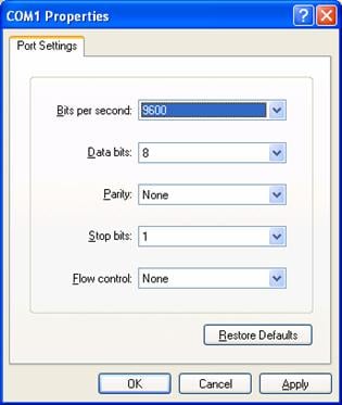
Figure 5-12 Attribute settings of HyperTerminal serial interface
II. Upgrading software through console port (XModem)
l Brief introduction to XModem
XModem, a type of file transfer protocol, is broadly applied for its simplicity and good performance. It transmits files through serial interfaces, supporting 128 bytes and 1 KB in terms of data unit, checksum and CRC in terms of checking mode, and multiple retransmissions (usually ten attempts) in the event that packet errors are found.
XModem completes transmission by the receiving program (receiver) and the sending program (sender). In XModem, the transmission begins with the sending of negotiation characters from the receiver for the purpose of check mode negotiation. After passing the negotiation, the sender is allowed to send the first data packet. Upon the receipt of the complete packet, the receiver checks the packet using the agreed checking mode and will send an ACK if the packet has passed the check and a NAK if not. Receiving the ACK, the sender will send the next packet; receiving the NAK instead, the sender will retransmit the previously sent packet.
l Xmodem application
1) In the Boot menu, enter 4, press Enter, and the system will access the serial interface submenu:
SERIAL SUBMENU
1. Download file to SDRAM through serial interface and boot
2. Download file to Flash through serial interface
3. Download file to CF card through serial interface
4. Modify serial interface boot parameter
0. Return to main menu
Enter your choice(0-4):4
2) Enter 4 in the serial interface submenu and press Enter to access the following interface for setting the parameters of the downloading serial interface:
1: 9600(default)
2: 19200
3: 38400
4: 57600
5: 115200
0: Return to serial submenu
please select an appropriate baudrate:
Enter your choice(1-5): 5
3) Select the appropriate downloading speed as needed. For example, enter 5 to select the downloading speed of 115200 bps, press Enter, and the system will display the following information in the terminal:
BaudRate is 115200 bps. Please change the terminal's speed to 115200 bps
4) At the prompt displayed in the last step, change the baud rate on the Console terminal to the same one selected for software downloading, disconnect the terminal and connect it again, press Enter, and the terminal will access the serial interface submenu again:
SERIAL SUBMENU
1. Download file to SDRAM through serial interface and boot
2. Download file to Flash through serial interface
3. Download file to CF card through serial interface
4. Modify serial interface boot parameter
0. Return to main menu
Enter your choice(0-4):3
& Note:
l After changing the baud rate, you must close the terminal emulation program and start it again for at least once in order to validate the new baud rate.
l In a Windows 98 operating system environment, you can perform the operations of disconnection and reconnection after changing the baud rate. In a Windows 2000 operating system, however, you must disconnect the terminal before setting the baud rate and connect the terminal after finishing the work.
l Since the software Release 2100 and later is quite large in size, you have to download it into the CF card.
5) Select a right place to store the downloaded file as needed. For example, enter 3 at the prompt displayed in the last step to download the file into the CF card of the switch, press Enter, and the system will display the following information on the terminal:
Please Select File .
XMODEM downloading ...CCC
6) Select Transfer > Send File in the terminal window. Click Browse in the pop-up dialog box (shown as the following figure), select the desired application, and change the protocol used for downloading to XModem.
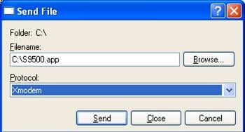
Figure 5-13 Send File dialog box
7) Click Send and the following interface pops up.
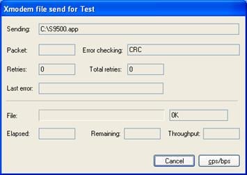
8) After downloading the program successfully, the system begins to write the data into the CF card. The downloading operation will end upon a successful write operation. Then, the system will access the serial interface submenu again, and the user can make selection as needed. The details will not be covered here.
XMODEM downloading ...CCC download successfully!
Free CF card space : 169902080 bytes
Writing CF card....Done
SERIAL SUBMENU
1. Download file to SDRAM through serial interface and boot
2. Download file to Flash through serial interface
3. Download file to CF card through serial interface
4. Modify serial interface boot parameter
0. Return to main menu
Enter your choice(0-4):
III. Upgrading software through management Ethernet port (TFTP)
l Introduction to TFTP
Trivial file transfer protocol (TFTP) is well suited to the file transfer between a server and a client that do not need complex interaction.
In TFTP, the transmission is initiated by the client. When downloading a file, the client sends a read request packet to the TFTP server, receives the data packets from the server, and sends the ACK to the server. When uploading a file, the client sends a write request packet to the TFTP server, then sends the data packets to the server, and receives the ACK from the server. The TFTP transmission files have two forms, i.e., binary for program transmission and ASCII for text transmission.
Following is the upgrading procedure described taking the S9512 working as a TFTP Client as an example.
l TFTP upgrade procedure
1) Connect the Switch to a PC where the desired file is located via the management/upgrade Ethernet port. (In this case, you should know the IP address of the PC. At the same time, connect the Switch to an external PC (that can be the same one that contains the desired file) via the Console port.
2) Run the TFTP Server program on the PC connected to the management/upgrade Ethernet port, and specify the path for upgrading the application files.
3) Run the terminal emulation program on the PC connected to the Console port, and boot the switch to access the Boot menu.
4) Enter 5 in the Boot menu. Press Enter and the system will access the download application program menu.
ETHERNET SUBMENU
1. Download file to SDRAM through ethernet interface and boot
2. Download file to Flash through ethernet interface
3. Download file to CF card through ethernet interface
4. Modify ethernet interface boot parameter
0. Return to main menu
Be sure to select 4 to modify boot parameter before downloading!
Enter your choice(0-4): 4
5) Enter 4 in the download application program menu to select TFTP for the software upgrading. Press Enter and then you can begin to set the related TFTP parameters:
Note: Two protocols for download, tftp & ftp.
You can modify the flags following the menu.
tftp--0x80, ftp--0x0.
& Note:
The information above prompts you to set the flags to 0x80 when you download files using TFTP and to 0x0 if using FTP.
'.' = clear field; '-' = go to previous field; ^D = quit
boot device :fei0
processor number :
host name : 9500 ,
file name : 9500.app
inet on ethernet (e) : 1.1.1.1
inet on backplane (b):
host inet (h) : 1.1.1.2
gateway inet (g) :
user (u) :
ftp password (pw) (blank = use rsh):
flags (f) :0x80
target name (tn) :
startup script (s) :
other (o) :
Write flash...done!
6) After you provide the required information, the system accesses the Ethernet interface submenu again:
ETHERNET SUBMENU
1. Download file to SDRAM through ethernet interface and boot
2. Download file to Flash through ethernet interface
3. Download file to CF card through ethernet interface
4. Modify ethernet interface boot parameter
0. Return to main menu
Enter your choice(0-4): 2
7) At the prompt displayed in step 6, select a place for the downloaded file (for example, select 3 to download the file to the CF card), and press Enter. The system will display the following information on the terminal screen:
Attached TCP/IP interface to fei0.
Attaching network interface lo0... done.
boot device : fei0
unit number : 0
processor number : 0
host name : 9500
file name : 9500.app
inet on ethernet (e) : 1.1.1.1
host inet (h) : 1.1.1.2
flags (f) : 0x80
Prepare for loading....OK
Loading......done
Free CF card space : 203915264 bytes
Writing CF card.....
......Done
8) The information displayed in the last step means a successful file downloading operation. In this case, the system accesses the Ethernet interface submenu again and the user can make selection as needed. The details will not be covered here.
ETHERNET SUBMENU
1. Download file to SDRAM through ethernet interface and boot
2. Download file to Flash through ethernet interface
3. Download file to CF card through ethernet interface
4. Modify ethernet interface boot parameter
0. Return to main menu
Enter your choice(0-4):
IV. Upgrading software through management Ethernet port (FTP)
l Introduction to FTP
The S9500 series applications can also be updated through the Ethernet port and using FTP.
Following is the upgrading procedure, using the S9512 working as an FTP Client as an example.
l Upgrade procedure
1) Connect the Switch to the PC containing the desired file via the management/upgrade Ethernet port. (In this case, you should know the IP address of the PC. At the same time, connect the Switch to an external PC (that can be the same one that contains the desired file) via the Console port.
2) Run FTP Server on the PC connected to the management/upgrade Ethernet port, specify the path of the upgrading file, and set the login username and password.
3) Run the terminal emulation program on the PC connected to the Console port, and boot the Switch to access the Boot menu.
4) For Steps 4 to 8, see the corresponding steps in the upgrading procedure via TFTP for reference.
& Note:
If you want to download files using FTP, please set the flags to 0x0 when setting the Ethernet interface parameters.
After downloading the host program through the Boot menu, you must specify it as the next boot program. In the following example, the host program is 9500.app.
MAIN MENU
1. Boot with default mode
2. Boot from Flash
3. Boot from CF card
4. Enter serial submenu
5. Enter ethernet submenu
6. Modify Flash description area
7. Modify bootrom password
0. Reboot
Enter your choice(0-7):
Enter your choice(0-7): 6
Please input '0' or '1' ('0':Boot from Flash, '1':Boot from CF card)
BootDev = 1
CF card FileName = S9500-XN.app 9500.app
The file name you input is 9500.app,
Are you sure? Yes or No(Y/N)Y
5.3.3 Local or Remote Loading through CLI
If your terminal is connected to the switch over a network, you can load Boot ROM and host program at the remote through CLI.
I. Loading using FTP
Run FTP server on a local PC, provided you have configured username and password and have set the correct file directory. Suppose IP address of the PC is 10.10.110.1. Log on to the switch using Telnet or through the Console port to send host program to the switch using FTP.
Suppose that the main boot file is SWITCH002.app; the active host program is SWITCH001.app; the Boot ROM program is SWITCHbtm.btm. You can follow these steps after logging on to the switch.
1) Download the software to the switch using FTP.
<H3C> ftp 10.10.110.1
Trying ...
Press CTRL+K to abort
Connected.
220 WFTPD 2.0 service (by Texas Imperial Software) ready for new user
User(none):9500
331 Give me your password, please
Password:
230 Logged in successfully
[ftp] get SWITCH002.app SWITCH002.app
[ftp] get Switchbtm.btm Switchbtm.btm
[ftp] bye
& Note:
If the switch has two SRPUs, you also can copy the host and Boot ROM program files to the standby SRPU.
2) Specify the next boot program. If the switch has two SRPUs, specify the load programs respectively for the active and standby SRPUs. Suppose the current standby SRPU is at slot 7.
l Load Boot ROM program
<H3C> boot bootrom CF:/Switchbtm.btm slot 6
<H3C> boot bootrom CF:/Switchbtm.btm slot 7
l Load host program
<H3C> boot boot-loader CF:/SWITCH002.app
<H3C>boot boot-loader CF:/SWITCH002.app
<H3C> display boot-loader
The app to boot of board 6 at the next time is: flash:/SWITCH002.app
The app to boot of board 6 at this time is: flash:/SWITCH001.app
The app to boot of board 7 at the next time is: flash:/SWITCH002.app
The app to boot of board 7 at this time is: flash:/SWITCH001.app
<H3C> reboot
![]() Caution:
Caution:
l You must reboot the switch using the reboot command to validate the host program.
l Make sure that you have saved other configurations before reboot. Otherwise, they might not survive a reboot.
l Power-off is forbidden during loading process.
Boot ROM and host program loading is completed now.
II. Remote and local loading using TFTP
Using TFTP is similar to using FTP in remote and local loading via commands. The only difference is that you use the tftp get command to download software to the switch. In this case, the switch can only be used as a TFTP client to download the software to its CF card from the TFTP server. The remaining steps after downloading are the same as those of remote loading using FTP.
5.3.4 Troubleshooting Software Upgrade
These types of problems may occur during software upgrade:
I. No response from SRPU serial interface
Check whether the serial interface cable is in good condition and if its attributes are set correctly (9600 bps).
II. Uploading configuration file or host program using FTP fails
Please check that
l The configuration is correct and if the FTP server is started.
l The Flash or the CF card has enough space for the target files.
l The FTP flag is selected and is set 0x0.
III. No configuration saving during LPU reboot
Before saving the configuration, you must check the operating status of the LPU. Do not save the configuration during the LPU reboot. Otherwise, the configuration you want to save may be lost.
IV. LPU program loading fails or you cannot register for a long period
l Check LPU type to see if this type is supported on the current host program.
l Check whether the LPU Boot ROM program matches the host program before upgrade.
l Check whether LPUs are well seated.
l Insert an LPU to different slots to check whether it is OK.
l Check whether the host program exists and if the current host program is the running one.
V. Insufficient Flash memory
l Empty the recycle bin when the LPU starts.
l Delete the unused files in the Flash.
l Load the files into the CF card.
5.3.5 Password Loss
If the Super password or Boot ROM password of the Switch is lost, contact the local agent or H3C technical support.