- Table of Contents
-
- H3C S9500 Series Routing Switches Installation Manual-(V2.03)
- 00-1Cover
- 01-Chapter1 Product Overview
- 02-Chapter2 Preparing for Installation
- 03-Chapter3 Installing the Switch
- 04-Chapter4 Commissioning the Switch
- 05-Chapter5 Troubleshooting and Maintaining the Switch
- 06-Appendix A Cable Management
- 07-Appendix B Engineering Labels for Cables
- 08-Appendix C Installation of Lightning Arrester for AC Power
- Related Documents
-
| Title | Size | Download |
|---|---|---|
| 03-Chapter3 Installing the Switch | 3 MB |
Chapter 3 Installing the Switch
3.2 Confirming Installation Preparation
3.3 Mounting the Switch in a Rack
3.3.2 Installing the Cable Management Bracket and Rack-Mounting Ears.
3.3.4 Verifying the Installation
3.4 Installing the Switch on a Workbench
3.5.1 In a common grounding environment
3.5.2 In other Grounding Environments
3.6.1 Installation Preparation
3.6.3 Connecting Power Cable(s)
3.7.1 Installation Preparations
3.8 Installing PoE Power Supply
3.8.2 Installing the PoE Power Entry Module
3.8.3 Connecting PoE Power Cables
3.9 Connecting Interface Cables
3.9.1 Cable Routing Recommendations
3.9.2 Connecting Console Cable
3.9.3 Connecting the AUX Cable
3.9.4 Connecting Network Cables
3.10 Verifying the Installation
Chapter 3 Installing the Switch
The S9500 series are designed for indoor applications.
![]() Warning:
Warning:
Do not touch any exposed wires, terminals or any parts labelled with a high-voltage hazard warning to avoid bodily injury.
3.1 Installation Flow

3.2 Confirming Installation Preparation
l Make sure that you have read Chapter 2 Preparing for the Installation carefully.
l All requirements mentioned in Chapter 2 Preparing for the Installation have been met.
3.3 Mounting the Switch in a Rack
3.3.1 Preparations
Before installation, make sure that:
l The cabinet is grounded and stable. The layout inside the cabinet for switch installation has been well done and there is no obstacle inside or around the cabinet.
l The switch is ready for installation and has been carried to a place near the cabinet.
3.3.2 Installing the Cable Management Bracket and Rack-Mounting Ears
For your convenience, a cable management bracket is shipped with the S9500 series. Take the following steps to install the cable management bracket.
1) Facing the LPU slots of the switch, insert the shipped cable management bracket into the left rack-mounting ear on which there is a recessed hole for installing the cable management bracket, and fix it with screws. (One cable management bracket for the S9505/S9508/S9508V and two for the S9512).
2) Install the rack-mounting ears onto the both sides of the switch, as shown in Figure 3-2.

Figure 3-2 Install the cable management bracket and rack-mounting ears
3.3.3 Mounting the Switch
& Note:
Make sure that supports have been installed in corresponding positions and the supports can bear the switch weight.
1) Two people are required to lift the switch. Put the switch on the supports and slide it into the cabinet until the rack-mounting ears touch against the front square-holed columns.
2) Fix the rack mounting ears onto the square-holed columns with screws.

Figure 3-3 Install the switch into a standard 19-inch rack
3.3.4 Verifying the Installation
After installing the switch into the rack, check the items listed in Table 3-1.
Table 3-1 Checklist for switch installation
|
Item |
Result |
Remarks |
|
|
Yes |
No |
||
|
The cable management bracket is well fixed on the left rack-mounting ear. |
|
|
|
|
The rack-mounting ears are well fixed on the switch. |
|
|
|
|
The installation position is right. |
|
|
|
|
The rack-mounting ears are well fixed on the rack |
|
|
|
3.4 Installing the Switch on a Workbench
When no 19-inch cabinet is available, you can place the switch on a clean and stable workbench.
3.4.1 Preparations
l Make sure that the workbench is sturdy enough to bear the weight of the switch and cables.
l Make sure that the workbench is flat and well grounded.
3.4.2 Procedure
Lift the switch onto the workbench with another person.
![]() Caution:
Caution:
Reserve at least 15.2 cm (6.0 in.) of clearance around the switch for heat dissipation.
3.5 Connecting the PGND Wire
![]() Caution:
Caution:
For the safety of operators and equipment, the switch must be well grounded. The resistance reading between switch chassis and the ground must be less than 1 ohm.
3.5.1 In a common grounding environment
Follow these steps to connect the PGND wire in a common grounding environment:
1) Remove the screw from the grounding hole in the switch chassis.
2) Wear the connector of the PGND wire accompanied with the switch on the grounding screw.
3) Insert the grounding screw into the grounding hole and screw it down.
4) Connect the other end of the PGND wire to the ground bar of the switch, as shown in Figure 3-4.

Figure 3-4 Connect the PGND wire
& Note:
Generally, the cabinets installed in equipment rooms are equipped with ground bar. In this case, you can connect the PGND wire of the switch to the ground bar for it.
3.5.2 In other Grounding Environments
The following are some methods for grounding the switch in different grounding environments.
& Note:
Rather than specifying the switch model or showing the actual location of the switch power input or grounding screw, the following figures are primarily intended for illustrating the switch grounding, either via grounding screw or power input, in specific grounding environments.
l If a ground bar is available, attach one end of the yellow-green PGND wire of the switch to a grounding bolt of the ground bar and fasten the captive screws.
![]() Caution:
Caution:
Note that neither the fire hydrant nor lightning rod of a building is suitable for grounding the switch. The PGND wire of the switch should be connected to the grounding device in the equipment room. (For the S9500 series, the grounding screw is on the rear panel. Connect it as illustrated in Figure 3-5).

|
(1) Rear panel of the switch |
(2) Grounding screw |
|
(3) PGND wire |
(4) Ground bar of the equipment room |
Figure 3-5 Ground the switch when a ground bar is available
l If there is no ground bar but earth nearby and the grounding body is allowed to be buried, you can simply hammer an angle iron or steel pipe no shorter than 0.5 m into the earth.
![]() Caution:
Caution:
The yellow-green PGND wire should be welded with the angle iron (steel pipe) and the joint should be processed against eroding. (For the S9500 series, the grounding screw is on the rear panel. Connect it as illustrated in Figure 3-5).

|
(1) Rear panel of the switch |
(2) Grounding screw |
|
(3) PGND wire |
(4) Ground |
|
(5) Angle steel (steel pipe) |
|
Figure 3-6 Ground the switch when allowed to bury grounding body nearby
l If both ground bar and the conditions for burying the grounding body are not available, an AC-powered Ethernet switch can be grounded using the PE wire of the AC power supply.
![]() Caution:
Caution:
Make sure that the PE wire of the AC power supply has been well grounded at the side of the power distribution room or AC power supply transformer.

|
(1) Front panel of the switch |
(2) AC power input |
|
(3) 3-core AC power cord |
(4) Transformer |
|
(5) Protection earth (PE) wire |
|
Figure 3-7 Ground the switch through the AC PE wire
l If no ground bar or condition for burying the grounding body is available, a DC-powered Ethernet switch can be grounded through the PGND strip of the power distribution frame (PDF).
![]() Caution:
Caution:
Make sure the RTN wire is well connected to the ground at the DC output of the PDF.

|
(1) Front panel of the switch |
(2) DC power input |
(3) NEG terminal |
|
(4) RTN terminal |
(5) PDF |
(6) -48V strip |
|
(7) RTN strip |
(8) PGND strip |
(9) Earth ground |
|
(10) PGND wire |
(11) Grounding screw |
(12) Rear panel of the switch |
Figure 3-8 Ground the switch through the PGND strip of the PDF
3.6 Installing a PSU
3.6.1 Installation Preparation
l Wear an ESD-preventive wrist strap and verify the ESD-preventive wrist strap is properly grounded.
l If there is a filler panel in the position where you will install a PSU, remove the filler panel.
![]() Caution:
Caution:
When you move a PSU, hold its bottom with one hand. Do not move it by just holding its handle. Otherwise, the PSU may be damaged.
3.6.2 Installation Procedure
I. Removing a PSU other than NEPS3500-A
The following procedure applies to all NEPS PSUs except NEPS3500-A.
1) Clutch the air filter cover by the upper and lower edges with your index finger and the thumb, and gently remove the air filter cover from a PSU.
& Note:
You can pull out the PSU handle only after removing the air filter cover.
2) Slide the PSU smoothly along the guide rails, until it snaps into the backplane.

3) Fasten the captive screws on both sides of the PSU with a Philips screwdriver and install the removed air filter cover onto the PSU.
4) Check that the power switch on the PSU is in the OFF position.
II. Installing NEPS3500-A
NEPS3500-A contains two sub-PSU slots. You can configure one or two 1800 W sub-PSUs. Follow these steps to install NEPS3500-A:
1) Install a NEPS3500-A enclosure into the switch.
2) Install one to two 1800 W sub-PSUs into the NEPS3500-A enclosure.
Table 3-2 Procedure of installing NEPS3500-A
|
Step |
Sub-step |
|
Install the NEPS3500-A enclosure into the switch |
1) Hold the handle on the enclosure with one hand and the bottom with the other hand, and gently slide the enclosure along the guide rails into the switch. 2) Fasten the captive screws on both sides of the enclosure with a Philips screwdriver. 3) Check that the power switch on the enclosure is in the OFF position. |
|
Install 1800 W sub-PSU(s) to the NEPS3500-A enclosure |
1) Pull down the handle on the sub-PSU (refer to the leftmost graph in Figure 3-10). 2) Slide the sub-PSU smoothly along the guide rails, until it snaps into the backplane. 3) Push the handle upward so that the sub-PSU moves further inside about 1 cm (0.39 in) until the handle locks the sub-PSU in place, as shown in the rightmost graph in Figure 3-10. |
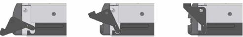
Figure 3-10 Install a 1800 W sub-PSU
3.6.3 Connecting Power Cable(s)
I. Connecting the AC power cord
![]() Caution:
Caution:
l For lightning protection, the AC power supply should be led through an external lightning device into the switch.
l Make sure the power switch on the PSU is in the OFF position before connecting the AC power cord.
Take the following steps to connect the AC power cord to NEPS1200-A, or NEPS2000-A:
1) Turn the clamp at the left of the PSU front panel rightwards.
2) Insert the plug at one end of the AC power cord into the socket of the PSU.
3) Turn the clamp leftwards until it grips the plug.
4) Insert the other end of the power cord into an external power socket.

|
(1) Connector-retention clamp |
(2) Input LED |
|
(3) Output LED |
(4) Fail LED |
|
(5) Power switch |
(6) PSU handle |
|
(7) AC power cord |
|
Figure 3-11 NEPS1200-A appearance

|
(1) Connector-retention clamp |
(2) Input LED |
|
(3) Output LED |
(4) Fail LED |
|
(5) Power switch |
(6) PSU handle |
|
(7) AC power cord |
|
Figure 3-12 NEPS2000-A appearance
Take the following steps to connect the AC power cord to NEPS3500-A:
1) Insert the plug at one end of the AC power cord into the socket on the PSU.
2) Install the clamp to the socket of the PSU until it grips the plug.
3) Insert the other end of the power cord into an external power socket.

|
(1) Power switch |
(2) Input LED |
|
(3) Output LED |
(4) Fail LED |
|
(5) PSU handle |
(6) AC power cord |
Figure 3-13 NEPS3500-A appearance
II. Connecting DC Power Cables
The DC power cables are connected to the terminal block, and are fixed with screws. A plastic cover plate is installed in front of the terminal block for the sake of connection reliability.
![]() Caution:
Caution:
l Completely power off the switch before connecting the DC power cord.
l Before removing or installing the DC power cables, you need to remove the plastic cover plate. Install it after installing/removing the DC power cables.
Take the following steps to connect the DC power cables:
1) Remove the plastic cover plate and loosen the fixing screws on the terminal block of the DC PSU with a Philips screwdriver.
2) Connect one end of the cable with –48V OT terminals (blue) to the NEG(–) terminal on the PSU and fasten the corresponding fixing screw. Connect the other end to the NEG (–) terminal of the source power supply.
3) Connect one end of the cable with GND OT terminals (black) to the RTN (+) terminal on the PSU and fasten the corresponding fixing screw. Connect the other end to the RTN (+) terminal of the power source.
4) Connect one end of the cable with PGND OT terminals (yellow-green) to the PGND terminal on the PSU and fasten the corresponding fixing screw. Connect the other end to the ground bar of the switch.
5) Install the plastic cover plate.

|
(1) Terminal block |
(2) Input LED |
(3) Output LED |
|
(4) Fail LED |
(5) Power switch |
(6) PSU handle |
Figure 3-14 NEPS1200-D appearance

|
(1) Terminal block |
(2) Input LED |
(3) Output LED |
|
(4) Fail LED |
(5) Power switch |
|
Figure 3-15 NEPS2000-D appearance
& Note:
l NEPS3500-D is similar to NEPS2000-D in appearance, as shown in Figure 3-15.
l The DC PSUs shown in the above figures are not equipped with plastic cover plates.
3.7 Installing a Board
The installation procedures of SRPUs, LPUs, and service boards are almost the same. The following section describes the installation procedure of LPUs.
3.7.1 Installation Preparations
l Wear the ESD-preventive wrist strap, making sure that it is properly grounded.
l Loosen the mounting screws on the blank filler panel where the SRPU is to be installed using a Phillips screwdriver and remove the blank filler panel.
l Prepare the LPU to be installed.
& Note:
l Put the removed blank filler panel away for future use.
l The LPUs of the S9500 series are hot-swappable.
3.7.2 Installation Procedure
Follow the procedure below to install an LPU:
1) Turn the ejector levers on the LPU outward simultaneously with both hands, insert the LPU straight into the chassis along the guide rails until it stops sliding (that is, the positioning pins on the ejector levers touch the positioning holes on the chassis).
2) Turn the ejector levers towards the front panel to drive the positioning pins into the positioning holes.

Figure 3-16 Install an LPU
3) Fix the LPU by fastening the mounting screws on the LPU with a Phillips screwdriver.
3.8 Installing PoE Power Supply
The S9505/S9508/S9512 uses PSE4500-A as an external PoE power supply, which is connected to the switch through the PoE power entry module at the front bottom of the switch to provide power for connected powered devices (PDs).
The following introduces the installation of PoE power supply on the S9505.
3.8.1 Installation Procedure
l Wear the ESD-preventive wrist strap, making sure that it is properly grounded.
l Remove blank filler panels in the power supply area if applicable.
3.8.2 Installing the PoE Power Entry Module
The PoE power entry module is hot-swappable.
Follow the steps below to install the PoE power entry module:
1) Unpack the PoE power entry module, which is shown in Figure 3-17.

Figure 3-17 PoE power entry module
2) Keep the PoE power entry module in the correct letter direction. (Do not turn it upside down. Otherwise, you will not be able to fully insert it into the chassis due to mis-plug prevention design of the module, nor can you fasten the chassis fixing screw.) Hold the bottom with one hand and the front panel with the other, and then slide it smoothly along the guide rails into the slot, until it snaps into the chassis. Make sure the plug of the PoE power entry module is fully connected with the socket inside the chassis. See Figure 3-18.

Figure 3-18 Install the PoE power entry module
3) Fasten the screws on the top of the PoE entry module with a Philips screwdriver.
3.8.3 Connecting PoE Power Cables
& Note:
This section only focuses on the cable connection between the external PoE power supply and the S9500 series switch. For the installation of the external PoE power supply, see the manual accompanying the power supply.
I. Grounding the PoE chassis
Follow these steps to ground the PoE chassis:
1) Connect the wiring terminal (with one M6 hole) of the 6 AWG cable to the grounding screw on the rear panel of the switch, as shown in Figure 3-19.
2) Connect the other end of the cable to the grounding bar or other grounding terminals.

|
(1) Chassis grounding screw |
Figure 3-19 Ground the PoE chassis
II. Connecting PoE power cables
1) Loosen the mounting screws on the PoE power entry module with a Phillips screwdriver.
2) Connect one –48V OT terminal of the blue DC power cable to the NEG (–) terminal of the PoE power entry module and fasten the mounting screw; connect the other end to the NEG (–) terminal of the external PoE power supply.
3) Connect the PGND OT terminal of the black DC power cable to the RTN (+) terminal of the PoE power entry module and fasten the mounting screw; connect the other end to the RTN (+) terminal of the external PoE power supply.
![]() Caution:
Caution:
l Observe the polarity signs on devices and connect the cables correctly.
l Choose right cables based on the load.

|
(1) NEG(–) terminal of DC output |
(2) RTN(+) terminal of DC output |
|
(3) AC input switch |
(4) AC input socket |
Figure 3-20 Input/output of external PoE power supply
3.9 Connecting Interface Cables
3.9.1 Cable Routing Recommendations
Interface cables and power cables should be routed separately. You can bind long cables with cable ties. For specific binding requirements, refer to Appendix A “Cable Binding”.
I. Workbench-mounted switch
All interface cables are routed to the left side (the cable management bracket) of the chassis, and power cables are routed to the front of the chassis.
II. Rack-Mounted switch
l The interface cables are bound on the cable management bracket on the left side of the chassis and are routed up or down to pass through the chassis top or the raised floor, depending on the available equipment room condition (that is, signal cables are routed into the chassis either from the cabling racks on the chassis top or from the cabling trough under the floor).
l All digital signal cable connectors should be put at the bottom of the cabinet. Do not put them outside the cabinet.
l Power cables run along the left-front of the chassis and out of the chassis either from the top or the raised floor, depending on the equipment room conditions (PDF, lightning protection box, and terminal block, etc.) in the equipment room.
![]() Caution:
Caution:
l Do not bind cables at the air exhaust vents of the switch to prevent premature cable aging.
l Fix cables as near the device as possible. The cables between the fixing point and device interfaces must be bound loosely.
l To identify cables, you can stick labels on them. For more information, refer to Appendix B “Engineering Labels for Cables”.
3.9.2 Connecting Console Cable
I. Introduction
Console cable is an 8-core shielded cable. At one end of the cable is a crimped RJ-45 connector that is to be plugged into the console port of the switch. At the other end of the cable is a DB-9 (female) connector. You can plug it into the 9-pin (male) serial port on the console terminal. The following figure illustrates the console cable.
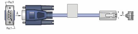
Table 3-3 Console cable pinouts
|
RJ-45 |
Signal |
DB-9 |
Signal |
|
1 |
RTS |
8 |
CTS |
|
2 |
DTR |
6 |
DSR |
|
3 |
TXD |
2 |
RXD |
|
4 |
CD |
5 |
SG |
|
5 |
GND |
5 |
SG |
|
6 |
RXD |
3 |
TXD |
|
7 |
DSR |
4 |
DTR |
|
8 |
CTS |
7 |
RTS |
II. Connecting the console cable
Take the following steps to connect the console cable, when configuring the switch on the terminal.
1) Plug the DB-9 female connector of the console cable into the serial port of the PC/terminal where the switch is to be configured.
2) Connect the RJ-45 connector of the console cable to the console port of the switch.

Figure 3-22 Connect the console cable
& Note:
The PC serial port is not hot-swappable, so you are not allowed to insert or remove the console cable into or from the PC serial port.
When connecting the console cable, first connect the DB9 end to the PC serial port and then the RJ45 end to the console port of the switch. And removing the console cable is just in inverse order.
When removing the console cable, first remove the RJ-45 end and then the DB9 end.
3.9.3 Connecting the AUX Cable
You need an AUX cable when configuring the S9500 series with the remote modem dial-up approach.
I. Introduction
The AUX cable is an 8-core shielded cable. At one end of the cable is an RS-232-compliant RJ-45 connector that can be plugged into the AUX port of the switch. At the other end is DB-9 (male) connector. You can plug it into the DB-9 (female) port of the modem. The AUX cable is the same as the console cable. For details, refer to Figure 3-21 and Table 3-3.
II. Connecting AUX cable
1) Plug the RJ-45 connector of the AUX cable into the AUX port of the switch.
2) Plug the DB-9 (male) connector at the other end into the serial port of the modem.
3.9.4 Connecting Network Cables
I. Introduction to RJ-45 connector
The 10/100/1000Base-T ports of the S9500 series support MDI/MDI-X auto-sensing. They are connected to category-5 shielded cables or above that are equipped with RJ-45 connectors.

II. Connection procedure
1) Plug one end of the network cable into the Ethernet RJ-45 port to be connected on the switch.
2) Plug the other end of the cable into the RJ-45 port of the peer device.
3.9.5 Connecting Fiber
I. Installing fiber management tray (optional)
& Note:
The installation method described below is based on an N68 cabinet. The installation procedure is only for your reference if you use a non-N68 cabinet.
A fiber management tray (FMT) is installed in a cabinet for winding redundant fibers between the S9500 and other devices.
1) Preparations
The installation prerequisites are as follows:
l The cabinet is fixed well.
l The device has been installed completely.
The installation involves the following materials:
l FMT
l M5×10 self-tapping screws (two screws for one FMT)
2) Installation Procedure
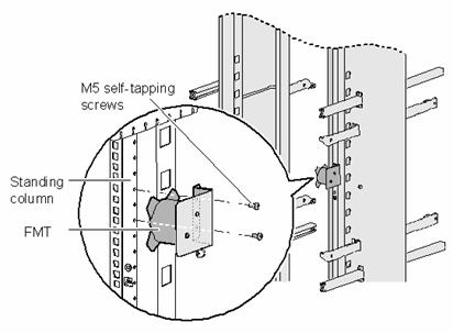
To install the fiber management tray, proceed as shown in Figure 3-24.
l Align the fiber management tray and the installation holes on the column of the cabinet.
l Use a Phillips screwdriver to fix each fiber management tray with two M5×10 self-tapping screws.
II. Introduction to fiber connector
& Note:
l When selecting a fiber network facility, make sure that the type of the connector and the fiber match the adopted optical port.
l Before connecting the fiber, make sure that the receive-end optical power does not exceed the optical module’s upper threshold of receiving optical power. Excessive receiving optical power is very likely to burn the optical module.
l All the megabit and gigabit optical modules available on the S9500 series are SFP modules and all interfaces on SFP modules adopt LC connectors.
Fiber connectors are indispensable passive components in an optical fiber communication system. They allow the removable connection between optical channels, which makes the optical system debugging and maintenance more convenient and the transit dispatching of the system more flexible. Among various fiber connectors, only the LC connector is introduced here.

III. Precautions
l Be sure to install the dust cover if the optical port is not connected to a fiber connector.
l Some invisible rays may be emitted from the optical port if the optical port is not connected to a fiber connector or the dust cover is removed. Therefore, never stare at the optical port directly.
l Fiber connectors must be protected under safe and reliable outer packing, and be fitted with dust caps. Fiber connectors must be installed with dust caps when they are not in use. Take care not to scratch their end face. Replace the dust cap if it loose or polluted.
l Before connecting a fiber, use dustfree paper and absolute alcohol to clean the end face of the fiber connector. You can brush the end face only in one direction. You also need to brush the end face of the other fiber connector.
l Never bend or curve a fiber when connecting it. After a fiber is installed well, the bend radius must be not less than 40 mm (the minimum dynamic bend radius is 20 D, and the minimum static bend radius is 10 D. D indicates the outer diameter of fiber jackets).
l If the fiber has to pass through a metallic board hole, the hole must have a sleek and fully filleted surface (the filleting radius must be not less than 2 mm). When passing through a metallic board hole or bending along the acute side of mechanical parts, the fiber must wear jackets or cushions.
l Insert and remove a plug with care. Never exert a fierce force to the fiber or plug; otherwise the plug may be damaged or the fiber may be broken. Never pull, press or extrude the fiber fiercely. For the allowed maximum tensile load and crush load, refer to Table 3-4.
Table 3-4 Allowed maximum tensile force and crush load
|
Period of force |
Tensile load (N) |
Crush load (N/100 mm) |
|
Short period |
150 |
500 |
|
Long term |
80 |
100 |
IV. Connection procedure
1) Connect one end of the fiber to the SFP module of the S9500 series.
2) Connect the other end of the fiber to the peer device.
3.10 Verifying the Installation
![]() Warning:
Warning:
Make sure that you have turned off the power before checking the installation in case of bodily injury and device damage.
After installing the switch, verify the installation against the following list. For the successful installation, all items must be normal.
Table 3-5 Installation checklist
|
Item |
Normal |
Abnormal (Description) |
|
Console cable |
|
|
|
PGND wire |
|
|
|
Power cables |
|
|
|
SRPUs |
|
|
|
LPUs/service boards |
|
|
|
Fan tray(s) |
|
|
|
PSUs |
|
|