- Table of Contents
-
- H3C S9500 Series Routing Switches Installation Manual-(V2.03)
- 00-1Cover
- 01-Chapter1 Product Overview
- 02-Chapter2 Preparing for Installation
- 03-Chapter3 Installing the Switch
- 04-Chapter4 Commissioning the Switch
- 05-Chapter5 Troubleshooting and Maintaining the Switch
- 06-Appendix A Cable Management
- 07-Appendix B Engineering Labels for Cables
- 08-Appendix C Installation of Lightning Arrester for AC Power
- Related Documents
-
| Title | Size | Download |
|---|---|---|
| 02-Chapter2 Preparing for Installation | 409 KB |
Chapter 2 Preparing for Installation
2.1.1 General Safety Recommendations
2.2 Examining Installation Site
2.2.1 Temperature Requirements
2.2.6 Power Supply Requirements
2.3 Cabinet-Mounting Requirements
2.3.2 Requirements of Supports
2.4 Requirements of Power Distribution Box
2.4.1 Installing the AC Power Distribution Box
2.4.2 Installing DC Power Distribution Box
Chapter 2 Preparing for Installation
2.1 Safety Recommendations
To avoid possible bodily injury and equipment damage, please read the following safety recommendations carefully before installing the S9500 series. The recommendations do not cover every possible hazardous condition.
2.1.1 General Safety Recommendations
l Take necessary safety measures to avoid injury and device damage. For example, wear an ESD-preventive wrist strap.
l Make sure that the ground is dry and flat and you have adopted anti-slip measures.
l Keep the chassis clean and dust-free. Do not place the switch on a moist area and avoid liquid flowing into the switch.
l Keep the chassis and installation tools away from walk areas.
2.1.2 Electrical Safety
l Look carefully for possible hazards in your work area, such as ungrounded power extension cables, missing safety grounds, and moist floors.
l Locate the emergency power-off switch in the room before installation. Shut the power off at once in case accident occurs.
l Unplug all the external cables (including power cords) before moving the chassis.
l Better not maintain the equipment alone when it has been powered.
l Never assume but check each time that power has been disconnected from a circuit.
2.1.3 ESD Damage Prevention
To prevent the electronic components from being damaged by the electrostatic discharge (ESD), you should not only take ESD measures where the switch is located, but also take the following precautions:
l Always wear an ESD-preventive wrist strap when installing components, especially the electronic printed circuit boards.
l Hold the edges of the PCB when necessary. Do not touch any electronic components or printed circuit.
Take the following steps to use the ESD-preventive wrist strap.
1) Wear the wrist strap on your wrist.
2) Lock the wrist strap tight around your wrist to keep good contact with the skin.
3) Insert the ESD-preventive wrist strap into the specially designed hole on the switch chassis or attach it to the grounding screw of the chassis the alligator clips.
4) Make sure that the ESD-preventive wrist strap is well grounded.
![]() Caution:
Caution:
For the sake of safety, check the resistance of the ESD-preventive wrist strap. The resistance reading should be in the range of 1M to 10 M ohm between human body and the ground.
2.1.4 Handling Safety
Since the S9500 series are rather large and heavy, you should follow the recommendations below:
l Remove all the external cables (including power cords) before moving the chassis.
l Do not move the switch alone.
l Move the switch slowly and stably. Keep in step with your partner and balance your bodies when moving the switch.
![]() Caution:
Caution:
You can only hold the handles at both sides of the chassis when moving the switch, but not the plastic panel of the chassis, the handle of the fan frame, the handle of the PSUs, the handle of the back cover of the chassis, or the air vents of chassis.
Any attempt to carry the switch with these parts may cause equipment damage or even bodily injury.
2.1.5 Laser Safety
S9500 series routing switches are class 1 laser products.
When an optional optical interface board of an S9500 switch is operating, do not stare into the open optical port because the laser emitted from it has very high power density and is harmful to your retina.
![]() Caution:
Caution:
The laser inside the optical fibre may hurt your eyes.
2.2 Examining Installation Site
The S9500 series can only be used indoors. To ensure that the switch works normally and to prolong its service lifetime, the following requirements should be met in terms of installation environment.
2.2.1 Temperature Requirements
To ensure the normal operation of a switch, the temperature in the room should be maintained within a proper range. Table 2-1 describes temperature requirements.
Table 2-1 Temperature requirements
|
Temperature |
Range |
|
Operating temperature |
0°C to 45°C (32°F to 113°F) |
|
Storage temperature |
–40°C to +70°C (–40°F to 158°F) |
The higher the temperature, the greater the damage it will do to the switch. Long-lasting high temperature will speed up the aging process of the insulating materials, greatly lower the reliability of the switch, and therefore affect its service life seriously.
![]() Caution:
Caution:
After the switch is moved to a high-temperature location, if condensate appears on the switch, you must dry the switch before power-on, thus to avoid damaging interior components due to short circuit.
2.2.2 Humidity Requirements
To ensure the normal operation of a switch, the humidity in the equipment room should be maintained within a proper range. Table 2-2 describes humidity requirements.
Table 2-2 Humidity requirements
|
Humidity |
Range |
|
Operating humidity (noncondensing) |
10% to 90% |
|
Storage humidity (noncondensing) |
5% to 95% |
Long-lasting high humidity in the equipment room is prone to poor insulation or even leakage of the insulating material. Sometimes, the mechanical performance deterioration, the rustiness and corrosion of some metal parts are also more likely to occur.
If the relative humidity is too low, the captive screws may become loose due to the insulation washer contraction. Meanwhile, the electrostatic is likely to be produced in the dry environment, which will jeopardize the CMOS circuit of the switch.
2.2.3 Cleanness Requirements
Dust is a hazard to the operating safety of the switch. The indoor dust accumulated on the chassis can cause electrostatic adsorption, which may result in the poor contact of the connector or metal contact point. This happens more frequently when indoor relative humidity is low, which will not only shorten the service life of the switch, but also cause communication failure.
The required specifications on dust content and particle diameter in an equipment room are shown in the following table.
Table 2-3 Limitation on dust content and particle diameter in the equipment room
|
Mechanical active material |
Content limit (particles/m³) |
|
Dust particle |
≤ 3 x 10⁴ (No visible dust on desk in three days) |
|
Note: Dust particle diameter ≥ 5 µm |
|
Besides the dust specifications, the equipment room of the switch should also meet the rigorous requirements for the content of salt, acid and sulfide in the air. These harmful gases could accelerate the metal erosion and the aging process of some parts. Incursion of harmful gases, such as SO2, H2S, NO2, NH3, and Cl2, should be prevented. The specific limitation values of these harmful gases are given in the following table.
Table 2-4 Harmful gas limits in an equipment room
|
Gas |
Average (mg/m³) |
Max. (mg/m³) |
|
SO2 |
0.3 |
1.0 |
|
H2S |
0.1 |
0.5 |
|
NO2 |
0.004 |
0.15 |
|
NH3 |
1.0 |
3 |
|
Cl2 |
0.1 |
0.3 |
2.2.4 EMS Requirements
Any possible interference sources, no matter whether outside or inside the system, affect the switch in use through capacitive coupling, inductive coupling, electromagnetic radiation, common impedance (including the grounding system) coupling or conducting line (power line, signalling line and transmission line etc). To prevent the interference, you should:
l Take effective measures against electrical net interference for power supply system.
l Separate the working ground of the switch from the grounding device of the power supply equipment or lightning-protection grounding device as far as possible.
l Keep the switch far away from the radio launcher, radar launcher, and high-frequency devices working in the high current.
l Adopt electromagnetic shielding if necessary.
& Note:
If necessary, take electromagnetic shielding measures against the interference.
2.2.5 Grounding Requirements
A good grounding system is not only the basis essential to the stable and reliable switch operation, but also an important guarantee of lightning protection, anti-interference and ESD-prevention. The user must provide good grounding system for the switch. The resistance between the chassis and the ground must be less than 1 ohm.
2.2.6 Power Supply Requirements
The following tables describe the specifications for AC and DC PSUs.
Table 2-5 Specifications for AC PSUs
|
Item |
Specifications |
||
|
NEPS1200-A |
NEPS2000-A |
NEPS3500-A |
|
|
Model |
S9505 |
S9508/S9512 |
S9508/S9512 |
|
Rated voltage range |
100 to 240 VAC, 50 Hz or 60 Hz |
100 to 120 VAC, 60 Hz 200 to 240 VAC, 50 Hz |
100 to 240 VAC, 50 Hz or 60 Hz |
|
Input voltage range |
90 to 264 VAC, 50 Hz or 60 Hz |
90 to 264 VAC, 50 Hz or 60 Hz |
90 to 264 VAC, 50 Hz or 60 Hz |
|
Max input current |
15 A |
15 A |
Single 1800W sub-PSU:15 A Two 1800W sub-PSUs: 30 A |
Table 2-6 Specifications for DC PSUs
|
Item |
Specifications |
||
|
NEPS1200-D |
NEPS2000-D |
NEPS3500-D |
|
|
Model |
S9505 |
S9508/S9512 |
S9508/S9512 |
|
Rated voltage range |
–48 VDC to –60 VDC |
–48 VDC to –60 VDC |
–48 VDC to –60 VDC |
|
Input voltage range |
–36 VDC to –72 VDC |
–36 VDC to –72 VDC |
–36 VDC to –72 VDC |
|
Max input current |
25 A |
42 A |
75 A |
|
Max output power |
1,200 W |
2,000 W |
3,500 W |
2.2.7 Space Requirements
For the sake of adequate ventilation and easy equipment maintenance, you are recommended to keep one meter of clearance between the rear/front of the switch cabinet and the wall surface or other devices. If the optional cabinet is desired, the clear height of the equipment room must be more than 3 meters inclusive.
2.3 Cabinet-Mounting Requirements
Before mounting the switch in a cabinet, make sure that the cabinet meets the following requirements.
2.3.1 Cabinet Requirements
I. Dimensions
A standard 19-inch cabinet is required.
You can install the switch in an N68 cabinet developed by H3C. There are two types of N68 cabinets available for the S9500 series:
l N68-18 model: 1.8-meter-high N68 cabinet (600 × 800 × 1800 mm, or 23.6 × 31.5 × 70.9 in.)
l N68-22 model: 2.2-meter-high N68 cabinet (600 × 800 × 2200 mm or 23.6 × 31.5 × 86.7 in.)
& Note:
For the procedure of installing and remodeling an N68 cabinet, refer to H3C N68 Cabinet Installation and Remodel Introduction.
You can also install the switch in a 19-inch cabinet provided by other vendors.
II. Weight bearing capacity and power
The cabinet must be able to bear the weight of the switch and its accessories. A 20% power margin should be reserved.
III. Grounding requirements
You must provide a good grounding system for the switch. The cabinet must be equipped with a grounding terminal, as shown in Figure 2-1.
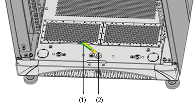
|
(1) Grounding cable |
(2) Grounding terminal |
IV. Heat dissipation
Air enters from the left of the S9500 series and exhausts from the right. Therefore, a clearance of at least 15.2 cm (6.0 in.) is required between the side panels of the cabinet and the switch. If the switch is to be installed in a closed cabinet, make sure that the cabinet has a good ventilation system.
2.3.2 Requirements of Supports
1) The length of supports depends on the cabinet depth.
2) You can use supports such as shelf or angles to install the switch into the cabinet. The supports must be able to bear the weight of the switch and its accessories.
Figure 2-2 shows a shelf.
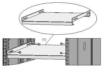
|
(1) Shelf |
Figure 2-3 shows an angle support.
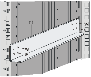
|
(1) Angle support |
2.4 Requirements of Power Distribution Box
You can install a power distribution box in the cabinet as required.
2.4.1 Installing the AC Power Distribution Box
I. Terminal Block
The terminal block is set on the bottom of a power distribution box.
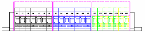
Figure 2-4 Terminal block structure diagram
The terminal block has 21 terminals to connect power cords: seven grey terminals, seven blue terminals and seven yellow-green terminals.
l The grey terminals from L1 to L7 are output ports for live wire. These ports are connected to each other.
l The blue terminals from N1 to N7 are output ports for neutral wire. These ports are connected to each other.
l The yellow-green terminals from PE1 to PE7 are output ports for earth wire. These ports are connected to each other and connected to the cabinet.
Table 2-7 Electrical specifications of the terminal block
|
Item |
Specification |
|
|
Input |
Rated current |
76A |
|
Rated voltage |
1000V |
|
|
Rated cross-sectional area |
16 mm2 |
|
|
Maximum current/maximum crimping area |
101A/25 mm2 |
|
|
Output |
seven loop outputs |
|
II. Power Distribution Box Appearance
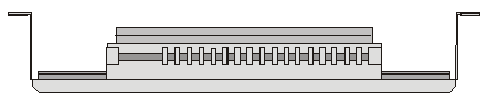
Figure 2-5 Front view of the power distribution box
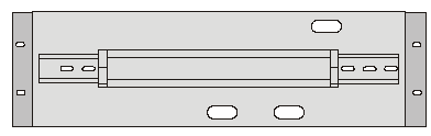
Figure 2-6 Top view of the power distribution box
![]() Caution:
Caution:
Make sure the power cord ports are covered with protection tube such that no wire tailpiece is exposed at any joint.
III. Connect power cords to the power distribution box
![]() Caution:
Caution:
The power distribution box takes AC high voltage. Do not operate it before breaking its power.
1) Use three cables to connect the client power distribution box to the terminal block of the cabinet power distribution box. You are recommended to use the cables with 16 mm2 cross-sectional area (the colors of the cables differ depending on the cable specifications in different countries). Connect the power cords according to the following relations:
l Live wire L in the client power distribution box — Live wire L in the cabinet power distribution box
l Neutral wire N in the client power distribution box — Neutral wire N in the cabinet power distribution box
l Earth wire G in the client power distribution box — Earth wire PE in the cabinet power distribution box
2) Use 3.5 m (11.5 ft) long cables to connect the cabinet power distribution box to the system power supply and PoE power supply. The three wires of each cable should be respectively connected to the ports L, N and PE of the power distribution box. Make sure the protection tubes are used and no wire tailpiece is exposed during the connection. You should connect power cord 1 to L1, N1 and PE1, power cord 2 to L2, N2 and PE2, and so on. The number of power cords depends on the cabinet configuration. Note that you should connect the brown wire to L (live wire), the blue wire to N (neutral wire), and yellow-green wire to PE (earth wire).
3) After finishing the connection of the cables, bind these cables in order with cable strap, wire them along the right side of the cabinet down, and connect them to the input ports of the system power supply and PoE power supply. You should make sure the cables are not loose.
IV. Installing the power distribution box
You should install the power distribution box on the top of the back of the N68 cabinet. You can adjust the location of the box in a little range.
Figure 2-7 describes the cable connections on the cabinet power distribution box.
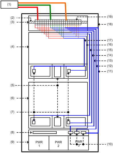
|
(1) User-supplied power distribution box |
(2) Guide rail |
(3) Power distribution box of the cabinet |
(4) S9505 chassis |
|
(5) PoE power entry module |
(6) S9505 chassis |
(7) System power input |
(8) Interface area on external PoE power supply panel |
|
(9) External PoE power supply |
(10) PoE AC socket |
(11)~(17) No.1 to No.7 power cable |
(18) N68 cabinet |
|
(19) Terminal block |
|
|
|
Figure 2-7 Cable connections on the power distribution box
2.4.2 Installing DC Power Distribution Box
I. Terminal Block
1) Terminal block structure diagram

|
(1) Air switch 1 |
(2) Air switch 2 |
(3) Guide rails |
|
(4) PGND wiring terminal block |
(5) BGND wiring terminal block |
(6) Isolator |
|
(7) Input terminal block |
|
|
Figure 2-8 Terminal block structure
As illustrated in Figure 2-8, the two leftmost input terminal blocks are DC input terminal blocks. Next to them are two air switches, each of which has a through-current capacity of 63A. On the rightmost side are 9 terminal blocks, 6 of which are BGND terminal blocks and the rest are PGND terminal blocks.
2) Diagram for connecting terminal blocks
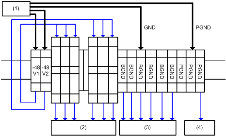
|
(1) Connected to user-supplied DC power |
(2) Connected to the negative terminal of –48 V DC power |
|
(3) Connected to the positive terminal of –48 V DC power |
(4) Grounded and connected to the cabinet |
Figure 2-9 Diagram for connecting DC input terminal blocks
3) Electrical performance of the terminal blocks
Table 2-8 Electrical performance of the terminal block
|
Item |
Specification |
|
|
Input |
Rated current |
63 A |
|
Rated voltage |
600 V |
|
|
Rated cross-sectional area |
16 mm2 |
|
|
Maximum current/maximum crimping area |
63A/16 mm2 |
|
4) Terminal block components
Table 2-9 illustrates terminal block components.
Table 2-9 Terminal block components
|
NO |
Name |
Quantity |
|
1 |
End bracket |
2 |
|
2 |
Cross connector |
3 |
|
3 |
Marker |
6 |
|
4 |
Terminal |
11 |
|
5 |
Clapboard |
7 |
|
6 |
Rail |
1 |
|
7 |
Circuit breaker |
6 |
II. Installing DC Power Distribution Box
To install power distribution box, take the following steps:
1) Install the DC input terminal blocks and air switches to the cabinet via the rail, as illustrated in Figure 2-10.
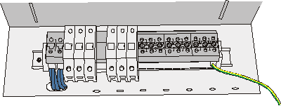
Figure 2-10 Install the DC input terminal blocks and air switches
2) Connect the DC input terminal blocks and the air switches with 6 mm2 cables and fix the cable properly. Also use a 6 mm2 cable for grounding, as illustrated in Figure 2-11.

Figure 2-11 Backplane diagram for connecting DC input terminal blocks and air switches
3) Fix the DC power distribution box onto the back of the cabinet.
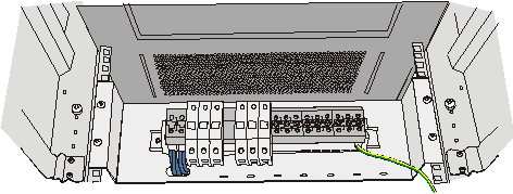
Figure 2-12 Diagram for fixing the power distribution box to the rear of the N68 cabinet
4) You can make the air switches to supply power to DC power modules by connecting the lower terminals of the air switches to DC power input terminals and supply voltages to DC power. (Refer to Figure 2-9 for detail. Note that the diameters of the cables need to be 6 mm2 or 10 mm2.)
5) You can use the BGND and PGND terminal blocks as needed. The rightmost PGND terminals must be connected to the cabinet using 6 mm2 cables, as illustrated in Figure 2-12.
6) Fasten the connected power cables with a wire and secure them onto the power distribution box.
7)
Use two 16 mm2 cables ![]() to connect the cabinet and the DC power distribution box. You need
to connect the two cables to the leftmost terminal blocks of the cabinet, as
illustrated in Figure 2-9.
to connect the cabinet and the DC power distribution box. You need
to connect the two cables to the leftmost terminal blocks of the cabinet, as
illustrated in Figure 2-9.
2.5 Installation Tools
Table 2-10 Required installation tools
|
General tools |
Measure and lineation tools |
Long tape, ruler (1 meter in length), gradienter, marking pen, powder marker, pencil |
|
Drills |
One percussion drill, several drill bits, one vacuum cleaner |
|
|
Fastening tools |
Plain screwdriver P4 - 75 mm Cross-head screwdriver P1 – 100 mm, P2 – 150 mm and P3 – 250 mm Box wrench M5 Ring spanner M6 Double ring spanner (10-12) or open ended spanner (10-12) |
|
|
Small tools |
Sharp-nose pliers, diagonal pliers, vices, hand-held electric drill, file, handsaw, crowbar, rubber hammer |
|
|
Auxiliary tools |
Brush, tweezers, paper knife, hand bellows, electric iron, solder wire, fork, ladder |
|
|
Special tools |
ESD-preventive wrist strap, cable stripper, crimping pliers, RJ-45 crimping pliers, wire punch-down tool |
|
|
Meters |
Multimeter, 500 V Meg-ohmmeter (used for measuring the insulation resistance), error detector, optical power meter, earth resistance tester |
|
& Note:
The instruments and tools are not shipped with the S9500 series. Therefore, you need to prepare the required instruments and tools.