- Table of Contents
-
- H3C S9500 Series Routing Switches Installation Manual-(V2.03)
- 00-1Cover
- 01-Chapter1 Product Overview
- 02-Chapter2 Preparing for Installation
- 03-Chapter3 Installing the Switch
- 04-Chapter4 Commissioning the Switch
- 05-Chapter5 Troubleshooting and Maintaining the Switch
- 06-Appendix A Cable Management
- 07-Appendix B Engineering Labels for Cables
- 08-Appendix C Installation of Lightning Arrester for AC Power
- Related Documents
-
| Title | Size | Download |
|---|---|---|
| 06-Appendix A Cable Management | 162 KB |
Appendix A Cable Management
A.1 Correct Use of Labels
Before binding the cables, you should fill in the labels for them correctly and stick them to the right position on the cables. For details, refer to the description of label usage in Appendix A Engineering Labels for Cables.
A.2 Cable Management Requirements
l Bind and put the cables inside the cabinet in a straight and neat way. No intertwinement or bending is allowed.

Figure A-1 Cable binding example I
l The bend radius of cable body cannot be less than twice of the cable diameter. The bend radius of the cable cannot be less than 5 times of its diameter at the place where it is led out of the connector;
l Different cables (power cord, signal cable, PGND wire, etc.) should be cabled and bound separately rather than together in the cabinet. If they are close to each other, you can cable them in cross-shape. For parallel cabling, the space between power cord and signal cable should be no less than 30 mm (1.2 in);
l The cable binding rack and cabling channel inside and outside the cabinet should be smooth and without sharp edges or tips;
l The metal cable management hole should have a smooth and fully rounded surface or wear a insulating bush;
l Use the right type of ties to bind the cables. Do not bind cables with joined ties. The following types of ties are available currently: 100 × 2.5 mm (3.9 in × 0.1 in), 150 × 3.6 mm (5.9 × 0.1 in), 300 ×3.6 mm (11.8 × 0.1 in), 530 × 9 mm (20.9 × 0.4 in), and 580 × 13 mm (22.8 × 0.5 in);
l Cut the extra parts of the ties neatly after binding the cables, leaving no sharp or angular tips. See the following figure:
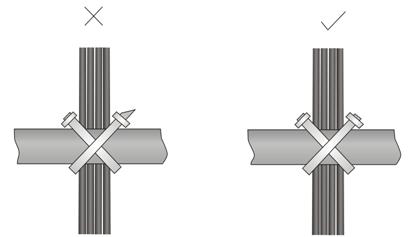
Figure A-2 Cable binding example II
l Bind the cables wherever cable bending cannot be avoided. However, the cable ties cannot be placed inside the bending area in case of the likelihood of cable core break due to excessive stress. See the following figure.
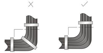
Figure A-3 Cable binding example III
l The spare cables or excessive cable parts should be folded and bound and placed at a right place in the cabinet or on the cabling channel. A “right place” refers to the place where the cables will not affect the operation of the device or impair the device, or be damaged;
l The power cords cannot be tied on the guides of any mobile components;
l Reserve some redundancy for the cables connecting to the mobile parts, the PGND wire of the door for example, to free the cables from possible stress. Such a mobile part should be installed in such a way that the extra cable segments will be kept from contacting the heat source, sharp points or edges. Use high temperature cables near the heat sources;
l For the cable terminals fixed using screw threads, the screws or nuts should be securely fastened and prevented from loosing. See the following figure;

|
(1) Flat washer |
(2) Spring washer |
(3) Nut |
Figure A-4 Cable fixing example
l When using a hard power cord, fix it near its terminal so as to free the terminal and the cable from stress;
l Do not use tapping screws to fasten the connecting terminals;
l The power cords of the same type and in the same direction should be bound together and kept neatly and straight;
The following table lists the requirements in the binding with cable ties.
Table A-1 Tie-binding parameters
|
Cable bundle diameter (mm) |
Space between bundles (mm) |
|
10 |
80 to 150 |
|
10 to 30 |
150 to 200 |
|
30 |
200 to 300 |
l No cable or bundle can tie a knot;
l The metal parts of the crimped cold-pressed terminal blocks (such as air switch) cannot stretch beyond the blocks.