- Table of Contents
- Related Documents
-
| Title | Size | Download |
|---|---|---|
| 04-EVPN VPWS over SRv6 configuration | 205.51 KB |
Configuring EVPN VPWS over SRv6
EVPN VPWS over SRv6 tasks at a glance
Configuring a cross-connect group and its EVPN instance
Applying a locator to a cross-connect
Configuring the route recursion mode
Mapping an AC to a cross-connect
Mapping an Ethernet service instance to a cross-connect
Configuring PEs to exchange BGP EVPN routes
Specifying a source address for the outer IPv6 header of SRv6-encapsulated EVPN VPWS packets
Verifying and maintaining EVPN VPWS over SRv6
Displaying BGP EVPN route information
Displaying EVPN VPWS over SRv6 running status
Displaying EVPN VPWS over SRv6 forwarding information
Clearing EVPN VPWS over SRv6 statistics
EVPN VPWS over SRv6 configuration examples
Example: Setting up an SRv6 tunnel between single-homed EVPN VPWS sites
Configuring EVPN VPWS over SRv6
About EVPN VPWS over SRv6
EVPN VPWS over SRv6 uses SRv6 tunnels to carry EVPN VPWS services. This technology establishes point-to-point connections between customer sites over the IPv6 backbone network and transparently forwards Layer 2 customer traffic over the IPv6 backbone network. For more information about EVPN VPWS configuration, see EVPN Configuration Guide.
Basic principle
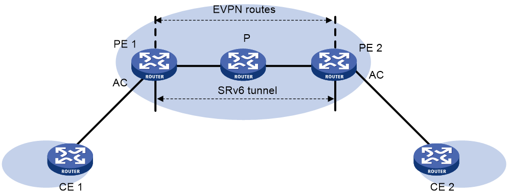
As shown in Figure 1, PEs set up an SRv6 tunnel by advertising End.DX2 SIDs to each other through BGP EVPN routes. On a PE, this SRv6 tunnel is used as a PW to encapsulate and forward Layer 2 data packets received from the local site and destined for a remote site. The devices on the IPv6 backbone transport network forward the SRv6-encapsulated packets according to the optimal routes calculated by an IGP. As a result, Layer 2 data packets of one customer site can be transparently forwarded to another site over the IPv6 backbone transport network.
Figure 1 EVPN VPWS over SRv6 network diagram
BGP EVPN route advertisement
A pair of PEs use BGP EVPN routes to establish PWs as follows:
1. A PE adds the local service ID and End.DX2 SID of a local cross-connect to Ethernet auto-discovery routes and advertises the routes to the remote PE.
2. After receiving the routes, the remote PE checks the service ID carried in the routes. If the service ID is the same as the remote service ID configured locally for a cross-connect, the PE establishes an SRv6 tunnel to the other PE. The SID flag of the SRv6 tunnel is the End.DX2 SID in the routes.
The two PEs both advertise End.DX2 SIDs to each other and establish two SRv6 tunnels at two directions. The two SRv6 tunnels form a PW to carry Layer 2 customer traffic. The PW is called an SRv6 PW.
Traffic forwarding
EVPN VPWS over SRv6 supports the SRv6 BE route recursion mode.
SRv6 BE mode
This mode is also called SID-based forwarding mode. In this mode, a PE forwards an SRv6 packet by searching the IPv6 routing table based on the End.DX2 SID encapsulated in the packet. A layer 2 packet is forwarded from CE 1 to CE 2 as follows:
1. CE 1 sends the Layer 2 packet to PE 1.
2. After PE 1 receives the packet on the AC connected to CE 1, it searches for the SRv6 PW (SRv6 tunnel) associated with the AC and finds the End.DX2 SID to reach PE 2.
3. PE 1 encapsulates the outer IPv6 header and SRH header for the packet. The End.DX2 SID is encapsulated in the outer IPv6 header as the destination IPv6 address. The source IPv6 address is the source address specified for the outer IPv6 header of SRv6-encapsulated EVPN VPWS packets.
4. PE 1 searches the IPv6 routing table based on the End.DX2 SID for the optimal IGP route and forwards the packet to P through the optimal IGP route.
5. P searches the IPv6 routing table based on the End.DX2 SID for the optimal IGP route and forwards the packet to PE 2 through the optimal IGP route.
6. PE 2 searches the local SID forwarding table for the End.DX2 SID and performs the following operations:
a. Removes the outer IPv6 header.
b. Matches the packet to an AC based on the End.DX2 SID.
c. Forwards the packet to CE 2 through the AC.
EVPN VPWS over SRv6 tasks at a glance
To configure EVPN VPWS over SRv6, perform the following tasks:
2. Configuring a cross-connect group and its EVPN instance
4. Applying a locator to a cross-connect
5. Configuring packet forwarding methods
¡ Configuring the route recursion mode
6. Mapping an AC to a cross-connect
7. Configuring PEs to exchange BGP EVPN routes
8. Specifying a source address for the outer IPv6 header of SRv6-encapsulated EVPN VPWS packets
Enabling L2VPN
1. Enter system view.
system-view
2. Enable L2VPN.
l2vpn enable
By default, L2VPN is disabled.
For more information about this command, see MPLS L2VPN commands in MPLS Command Reference.
Configuring a cross-connect group and its EVPN instance
1. Enter system view.
system-view
2. Create a cross-connect group and enter its view.
xconnect-group group-name
For more information about this command, see MPLS L2VPN commands in MPLS Command Reference.
3. (Optional.) Configure a description for the cross-connect group.
description text
By default, no description is configured for a cross-connect group.
For more information about this command, see MPLS L2VPN commands in MPLS Command Reference.
4. (Optional.) Bring p the cross-connect group.
undo shutdown
By default, a cross-connect group is not administratively down.
For more information about this command, see MPLS L2VPN commands in MPLS Command Reference.
5. Create an EVPN instance for the cross-connect group and enter its view.
evpn encapsulation srv6
6. Configure an RD for the EVPN instance.
route-distinguisher route-distinguisher
By default, no RD is configured for the EVPN instance of a cross-connect group.
For more information about this command, see EVPN commands in EVPN Command Reference.
7. Configure route targets for the EVPN instance.
vpn-target { vpn-target&<1-8> } [ both | export-extcommunity | import-extcommunity ]
By default, no route targets are configured for the EVPN instance of a cross-connect group.
For more information about this command, see EVPN commands in EVPN Command Reference.
|
Parameter |
Description |
|
export-extcommunity |
Do not specify the same export targets for the EVPN instances of different cross-connect groups. Do not specify the same export targets for the EVPN instances of a cross-connect group and a VSI. As a best practice, the export targets of the EVPN instance of a cross-connect group do not match the import targets configured in VPN instance view, VPN instance EVPN view, public instance view, public instance EVPN view, or VSI EVPN instance view. |
|
import-extcommunity |
As a best practice, the import targets of the EVPN instance of a cross-connect group do not match the export targets configured in VPN instance view, VPN instance EVPN view, public instance view, public instance EVPN view, or VSI EVPN instance view. |
8. Return to cross-connect group view.
quit
9. Create a cross-connect and enter its view.
connection connection-name
For more information about this command, see MPLS L2VPN commands in MPLS Command Reference.
Configuring SRv6 SIDs
Restrictions and guidelines
For more information about the commands in this task, see SRv6 commands in Segment Routing Command Reference.
When you configure SRv6 SIDs, make sure the IPv6 address for a locator is the main IPv6 address for an interface.
Procedure
1. Enter system view.
system-view
2. Enable SRv6 and enter SRv6 view.
segment-routing ipv6
3. Configure a locator and enter SRv6 locator view.
locator locator-name [ ipv6-prefix ipv6-address prefix-length [ args args-length | static static-length ] * ]
Applying a locator to a cross-connect
About this task
Perform this task to apply a locator to a cross-connect for the cross-connect to apply for End.DX2 SIDs from the locator.
Procedure
1. Enter system view.
system-view
2. Enter cross-connect group view.
xconnect-group group-name
3. Enter cross-connect view.
connection connection-name
4. Apply a locator to the cross-connect.
segment-routing ipv6 locator locator-name [ auto-sid-disable ]
By default, no locator is applied to a cross-connect.
5. Create an SRv6 PW and enter SRv6 PW view.
evpn local-service-id local-service-id remote-service-id remote-service-id [ tunnel-policy tunnel-policy-name ]
For more information about this command, see EVPN commands in EVPN Command Reference.
Configuring the route recursion mode
About this task
After a PE receives a customer packet destined for an End.DX2 SID, it forwards the packet according to the route recursion mode.
· SRv6 BE mode—This mode is also called SID-based forwarding mode. In this mode, the PE first encapsulates the End.DX2 SID into the packet. Then, the PE searches the IPv6 routing table based on the End.DX2 SID encapsulated in the packet to forward the packet.
Prerequisites
To use the SRv6 TE mode or the SRv6 TE and SRv6 BE hybrid mode, you must configure a tunnel policy and SRv6 TE policy. For more information, see tunnel policy configuration in MPLS Configuration Guide and "Configuring SRv6 TE policies."
Procedure
1. Enter system view.
system-view
2. Enter cross-connect group view.
xconnect-group group-name
3. Enter cross-connect group EVPN instance view.
evpn encapsulation srv6
4. Configure the route recursion mode.
segment-routing ipv6 best-effort
By default, a PE searches the IPv6 routing table based on the next hop of a matching EVPN route to forward traffic.
Mapping an AC to a cross-connect
Mapping an Ethernet service instance to a cross-connect
1. Enter system view.
system-view
2. Enter cross-connect group view.
xconnect-group group-name
3. Enter cross-connect view.
connection connection-name
4. Map an Ethernet service instance to the cross-connect.
ac interface interface-type interface-number service-instance instance-id [ access-mode vlan ]
By default, no Ethernet service instance is mapped to a cross-connect.
For more information about this command, see MPLS L2VPN commands in MPLS Command Reference.
Configuring PEs to exchange BGP EVPN routes
1. Enter system view.
system-view
2. Enter BGP instance view.
bgp as-number [ instance instance-name ]
3. Configure an IPv6 peer or peer group.
peer { group-name | ipv6-address [ prefix-length ] } as-number as-number
For more information about this command, see BGP commands in Layer 3—IP Routing Command Reference.
4. Specify the source interface of TCP connections to a peer or peer group.
peer { group-name | ipv6-address [ prefix-length ] } connect-interface interface-type interface-number
By default, BGP uses the IPv6 address of the output interface in the optimal route to the BGP peer or peer group as the source address of TCP connections to the peer or peer group.
For more information about this command, see BGP commands in Layer 3—IP Routing Command Reference.
5. Enter BGP EVPN address family view.
address-family l2vpn evpn
For more information about this command, see EVPN commands in EVPN Command Reference.
6. Enable BGP to exchange EVPN routes with an IPv6 peer or peer group.
peer { group-name | ipv6-address [ prefix-length ] } enable
By default, BGP cannot exchange EVPN routes with an IPv6 peer or peer group.
For more information about this command, see BGP commands in Layer 3—IP Routing Command Reference.
7. Enable BGP to advertise SRv6-encapsulated BGP EVPN routes to a peer or peer group.
peer { group-name | ipv6-address [ prefix-length ] } advertise encap-type srv6
By default, BGP advertises VXLAN-encapsulated BGP EVPN routes to a peer or peer group.
Specifying a source address for the outer IPv6 header of SRv6-encapsulated EVPN VPWS packets
Restrictions and guidelines
To ensure correct traffic forwarding in an EVPN VPWS over SRv6 network, you must specify a source address for the outer IPv6 header of SRv6-encapsulated EVPN VPWS packets.
You cannot specify a loopback address, link-local address, multicast address, or unspecified address as the source IPv6 address. You must specify an IPv6 address of the local device as the source IPv6 address, and make sure the IPv6 address has been advertised by a routing protocol. As a best practice, specify a loopback interface address of the local device as the source IPv6 address.
Procedure
1. Enter system view.
system-view
2. Enter SRv6 view.
segment-routing ipv6
3. Specify a source address for the outer IPv6 header of SRv6-encapsulated EVPN VPWS packets.
encapsulation source-address ipv6-address [ ip-ttl ttl-value ]
By default, no source address is specified for the outer IPv6 header of SRv6-encapsulated EVPN VPWS packets.
Verifying and maintaining EVPN VPWS over SRv6
Displaying BGP EVPN route information
Perform display tasks in any view.
· Display BGP peer group information.
display bgp [ instance instance-name ] group l2vpn evpn [ group-name group-name ]
For more information about this command, see basic BGP commands in Layer 3—IP Routing Command Reference.
· Display BGP peer or peer group information.
display bgp [ instance instance-name ] peer l2vpn evpn [ ipv4-address mask-length | { ipv4-address | group-name group-name } log-info | [ ipv4-address ] verbose ]
For more information about this command, see basic BGP commands in Layer 3—IP Routing Command Reference.
· Display information about BGP update groups.
display bgp [ instance instance-name ] update-group l2vpn evpn [ ipv4-address ]
For more information about this command, see basic BGP commands in Layer 3—IP Routing Command Reference.
· Display BGP EVPN routes.
display bgp [ instance instance-name ] l2vpn evpn [ peer { ipv4-address | ipv6-address } { advertised-routes | received-routes } [ statistics ] | [ route-distinguisher route-distinguisher | route-type { es | imet } ] * [ { evpn-route route-length | evpn-prefix } [ advertise-info ] | ipv4-address | ipv6-address | mac-address ] | statistics ]
For more information about this command, see EVPN Command Reference.
Displaying EVPN VPWS over SRv6 running status
Perform display tasks in any view.
· Display information about peers that are automatically discovered through BGP.
display evpn auto-discovery { mac-ip [ srv6 ] [ peer ip-address] [ vsi vsi-name ] | macip-prefix [ nexthop next-hop ] [ count ] }
For more information about this command, see EVPN Command Reference.
· Display EVPN ES information.
display evpn es { local [ count | [ vsi vsi-name ] [ esi esi-id ] [ verbose ] ] | remote [ vsi vsi-name ] [ esi esi-id ] [ nexthop next-hop ] [ verbose ]}
For more information about this command, see EVPN Command Reference.
· Display EVPN information about cross-connects.
display evpn route xconnect-group [ name group-name [ connection connection-name ] ] [ count ]
For more information about this command, see EVPN Command Reference.
· Display information about cross-connect groups.
¡ display l2vpn xconnect-group [ evpn-srv6 | name group-name ] [ count | verbose ]
¡ display l2vpn xconnect-group name group-name connection connection-name [ verbose ]
· Display L2VPN SRv6 information.
display l2vpn peer srv6 [ xconnect-group group-name ] [ state-machine | verbose ]
Displaying EVPN VPWS over SRv6 forwarding information
To display SRv6 forwarding information, execute the following command in any view:
display l2vpn forwarding srv6 [ xconnect-group group-name ] [ slot slot-number ] [ verbose ]
Clearing EVPN VPWS over SRv6 statistics
To clear SRv6 PW packet statistics, execute the following command in user view:
reset l2vpn statistics srv6-pw [ vsi vsi-name [ peer ipv6-address ] ]
EVPN VPWS over SRv6 configuration examples
Example: Setting up an SRv6 tunnel between single-homed EVPN VPWS sites
Network configuration
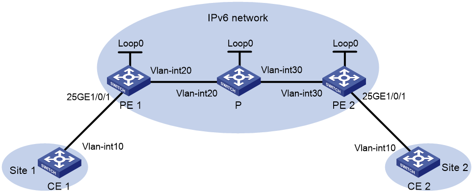
As shown in Figure 6, set up an SRv6 tunnel between PE 1 and PE 2 for users in VLAN 10 of site 1 and site 2 to communicate through EVPN VPWS over the IPv6 backbone network.
|
Device |
Interface |
IP address |
Device |
Interface |
IP address |
|
CE 1 |
Vlan10 |
10::1/64 |
P |
Loop0 |
3::3/128 |
|
PE 1 |
Loop0 |
1::1/128 |
|
Vlan20 |
20::3/64 |
|
|
25GE1/0/1 |
- |
|
Vlan30 |
30::3/64 |
|
|
Vlan20 |
20::1/64 |
PE 2 |
Loop0 |
2::2/128 |
|
CE 2 |
Vlan10 |
10::2/64 |
|
25GE1/0/1 |
- |
|
|
|
|
|
Vlan30 |
30::2/64 |
Prerequisites
Create VLANs on all devices and assign interfaces to the VLANs.
Procedure
1. Configure CE 1.
<CE1> system-view
[CE1] interface vlan-interface 10
[CE1-Vlan-interface10] ipv6 address 100::1 64
[CE1-Vlan-interface10] quit
2. Configure PE 1:
# Run OSPFv3 on PE 1 and use OSPFv3 to advertise SIDs.
<PE1> system-view
[PE1] ospfv3
[PE1-ospfv3-1] router-id 1.1.1.1
[PE1-ospfv3-1] segment-routing ipv6 locator aaa
[PE1-ospfv3-1] area 0.0.0.0
[PE1-ospfv3-1-area-0.0.0.0] quit
[PE1-ospfv3-1] quit
# Configure interface Loopback 0.
[PE1] interface loopback 0
[PE1-LoopBack0] ipv6 address 1::1 128
[PE1-LoopBack0] ospfv3 1 area 0
[PE1-LoopBack0] quit
# Enable L2VPN.
[PE1] l2vpn enable
# Configure VLAN-interface 20, the interface connected to P.
[PE1] interface vlan-interface 20
[PE1-Vlan-interface20] ipv6 address 20::1 64
[PE1-Vlan-interface20] ospfv3 1 area 0
[PE1-Vlan-interface20] undo shutdown
[PE1-Vlan-interface20] quit
# Configure PE 1 to establish IBGP neighbor relationship with PE 2 and enable BGP EVPN to advertise routes in SRv6 encapsulation to PE 2.
[PE1] bgp 100
[PE1-bgp-default] router-id 1.1.1.1
[PE1-bgp-default] peer 2::2 as-number 100
[PE1-bgp-default] peer 2::2 connect-interface loopback 0
[PE1-bgp-default] address-family l2vpn evpn
[PE1-bgp-default-evpn] peer 2::2 enable
[PE1-bgp-default-evpn] peer 2::2 advertise encap-type srv6
[PE1-bgp-default-evpn] quit
[PE1-bgp-default] quit
# Create Ethernet service instance 1000 to match VLAN 10 on site-facing interface Twenty-FiveGigE 1/0/1.
[PE1] interface twenty-fivegige 1/0/1
[PE1-Twenty-FiveGigE1/0/1] service-instance 1000
[PE1-Twenty-FiveGigE1/0/1-srv1000] encapsulation s-vid 10
[PE1-Twenty-FiveGigE1/0/1-srv1000] quit
[PE1-Twenty-FiveGigE1/0/1] quit
# Create a cross-connect group named vpna, create an EVPN instance for it, and enable SRv6 encapsulation. Configure an RD and route targets for the EVPN instance and enable SRv6 BE route recursion mode.
[PE1] xconnect-group vpna
[PE1-xcg-vpna] evpn encapsulation srv6
[PE1-xcg-vpna-evpn-srv6] route-distinguisher 1:1
[PE1-xcg-vpna-evpn-srv6] vpn-target 1:1 export-extcommunity
[PE1-xcg-vpna-evpn-srv6] vpn-target 1:1 import-extcommunity
[PE1-xcg-vpna-evpn-srv6] segment-routing ipv6 best-effort
[PE1-xcg-vpna-evpn-srv6] quit
# Create cross-connect pw1 and map Ethernet service instance 1000 on Twenty-FiveGigE 1/0/1 to the cross-connect. Create an SRv6 tunnel on the cross-connect.
[PE1-xcg-vpna] connection pw1
[PE1-xcg-vpna-pw1] ac interface twenty-fivegige 1/0/1 service-instance 1000
[PE1-xcg-vpna-pw1-Twenty-FiveGigE1/0/1-srv1000] quit
[PE1-xcg-vpna-pw1] evpn local-service-id 1 remote-service-id 2
[PE1-xcg-vpna-pw1-1-2] quit
[PE1-xcg-vpna-pw1] segment-routing ipv6 locator aaa
[PE1-xcg-vpna-pw1] quit
[PE1-xcg-vpna] quit
# Specify a source IP address for the outer IPv6 header of SRv6-encapsulated packets, and configure a locator to apply for End.DX2 SIDs.
[PE1] segment-routing ipv6
[PE1-segment-routing-ipv6] encapsulation source-address 1::1
[PE1-segment-routing-ipv6] locator aaa ipv6-prefix 100:: 64 static 32
[PE1-segment-routing-ipv6-locator-aaa] quit
[PE1-segment-routing-ipv6] quit
3. Configure PE 2:
# Run OSPFv3 on PE 2 and use OSPFv3 to advertise SIDs.
<PE2> system-view
[PE2] ospfv3
[PE2-ospfv3-1] router-id 2.2.2.2
[PE2-ospfv3-1] segment-routing ipv6 locator aaa
[PE2-ospfv3-1] area 0.0.0.0
[PE2-ospfv3-1-area-0.0.0.0] quit
[PE2-ospfv3-1] quit
# Configure interface Loopback 0.
[PE2] interface loopback 0
[PE2-LoopBack0] ipv6 address 2::2 128
[PE2-LoopBack0] ospfv3 1 area 0
[PE2-LoopBack0] quit
# Enable L2VPN.
[PE2] l2vpn enable
# Configure VLAN-interface30, the interface connected to P.
[PE2] interface vlan-interface 30
[PE2-Vlan-interface30] ipv6 address 30::2 64
[PE2-Vlan-interface30] ospfv3 1 area 0.0.0.0
[PE2-Vlan-interface30] undo shutdown
[PE2-Vlan-interface30] quit
# Configure PE 2 to establish IBGP neighbor relationship with PE 1, and enable BGP EVPN to advertise routes in SRv6 encapsulation to PE 1.
[PE2] bgp 100
[PE2-bgp-default] router-id 2.2.2.2
[PE2-bgp-default] peer 1::1 as-number 100
[PE2-bgp-default] peer 1::1 connect-interface loopback 0
[PE2-bgp-default] address-family l2vpn evpn
[PE2-bgp-default-evpn] peer 1::1 enable
[PE2-bgp-default-evpn] peer 1::1 advertise encap-type srv6
[PE2-bgp-default-evpn] quit
[PE2-bgp-default] quit
# Create Ethernet service instance 1000 to match VLAN 10 on site-facing interface Twenty-FiveGigE 1/0/1.
[PE2] interface twenty-fivegige 1/0/1
[PE2-Twenty-FiveGigE1/0/1] service-instance 1000
[PE2-Twenty-FiveGigE1/0/1-srv1000] encapsulation s-vid 10
[PE2-Twenty-FiveGigE1/0/1-srv1000] quit
[PE2-Twenty-FiveGigE1/0/1] quit
# Create a cross-connect group named vpna, create an EVPN instance for it, and enable SRv6 encapsulation. Configure an RD and route targets for the EVPN instance and enable SRv6 BE route recursion mode.
[PE2] xconnect-group vpna
[PE2-xcg-vpna] evpn encapsulation srv6
[PE2-xcg-vpna-evpn-srv6] route-distinguisher 1:1
[PE2-xcg-vpna-evpn-srv6] vpn-target 1:1 export-extcommunity
[PE2-xcg-vpna-evpn-srv6] vpn-target 1:1 import-extcommunity
[PE2-xcg-vpna-evpn-srv6] segment-routing ipv6 best-effort
[PE2-xcg-vpna-evpn-srv6] quit
# Create cross-connect pw1 and map Ethernet service instance 1000 on Twenty-FiveGigE 1/0/1 to the cross-connect. Create an SRv6 tunnel on the cross-connect.
[PE2-xcg-vpna] connection pw1
[PE2-xcg-vpna-pw1] ac interface twenty-fivegige 1/0/1 service-instance 1000
[PE2-xcg-vpna-pw1-Twenty-FiveGigE1/0/1-srv1000] quit
[PE2-xcg-vpna-pw1] evpn local-service-id 2 remote-service-id 1
[PE2-xcg-vpna-pw1-2-1] quit
[PE2-xcg-vpna-pw1] segment-routing ipv6 locator aaa
[PE2-xcg-vpna-pw1] quit
[PE2-xcg-vpna] quit
# Specify a source IP address for the outer IPv6 header of SRv6-encapsulated packets, and configure a locator to apply for End.DX2 SIDs.
[PE2] segment-routing ipv6
[PE2-segment-routing-ipv6] encapsulation source-address 2::2
[PE2-segment-routing-ipv6] locator aaa ipv6-prefix 200:: 64 static 32
[PE2-segment-routing-ipv6-locator-aaa] quit
[PE2-segment-routing-ipv6] quit
4. Configure P:
# Run OSPFv3 on P.
<P> system-view
[P] ospfv3
[P-ospfv3-1] router-id 3.3.3.3
[P-ospfv3-1] area 0.0.0.0
[P-ospfv3-1-area-0.0.0.0] quit
[P-ospfv3-1] quit
# Configure IPv6 addresses for interfaces and run OSPFv3 on the interfaces.
[P] interface loopback 0
[P-LoopBack0] ipv6 address 3::3 128
[P-LoopBack0] ospfv3 1 area 0
[P-LoopBack0] quit
[P] interface vlan-interface 20
[P-Vlan-interface20] ipv6 address 20::3 64
[P-Vlan-interface20] ospfv3 1 area 0
[P-Vlan-interface20] quit
[P] interface vlan-interface 30
[P-Vlan-interface30] ipv6 address 30::3 64
[P-Vlan-interface30] ospfv3 1 area 0
[P-Vlan-interface30] quit
5. Configure CE 2.
<CE2> system-view
[CE2] interface vlan-interface 10
[CE2-Vlan-interface10] ipv6 address 100::2 64
[CE2-Vlan-interface10] quit
Verifying the configuration
# Verify that an SRv6 tunnel has been established between PE 1 and PE 2.
[PE1] display l2vpn peer srv6
Total number of SRv6 Tunnels: 1
1 up, 0 blocked, 0 down
Xconnect-group Name: vpna
Peer : 2::2
Flag : Main
State : Up
Remote SrvID : 2
# Verify that the SRv6 forwarding information on PE 1 is correct. You can see input and output SID information about the SRv6 tunnel.
[PE1] display l2vpn forwarding srv6
Total number of cross-connections: 1
Total number of SRv6 tunnels: 1, 1 up, 0 blocked, 0 down
Xconnect-group Name : vpna
Connection Name : pw1
Link ID : 0x8000000 Type: BE State: Up
In SID : 100::1:0:2
Out SID : 200::1:0:2
# Verify that CE 1 and CE 2 can ping each other. (Details not shown.)