- Table of Contents
-
- 14-Network Management and Monitoring Configuration Guide
- 00-Preface
- 01-System maintenance and debugging configuration
- 02-NQA configuration
- 03-iNQA configuration
- 04-iFIT configuration
- 05-SRPM configuration
- 06-NTP configuration
- 07-PTP configuration
- 08-Network synchronization configuration
- 09-SNMP configuration
- 10-RMON configuration
- 11-NETCONF configuration
- 12-CWMP configuration
- 13-EAA configuration
- 14-Process monitoring and maintenance configuration
- 15-Sampler configuration
- 16-Mirroring configuration
- 17-NetStream configuration
- 18-IPv6 NetStream configuration
- 19-TCP connection trace configuration
- 20-Performance management configuration
- 21-Fast log output configuration
- 22-Flow log configuration
- 23-Information center configuration
- 24-Packet capture configuration
- 25-Flow monitor configuration
- Related Documents
-
| Title | Size | Download |
|---|---|---|
| 06-NTP configuration | 755.58 KB |
Restrictions and guidelines: NTP configuration
Client/server mode tasks at a glance
Symmetric active/passive mode tasks at a glance
Broadcast mode tasks at a glance
Multicast mode tasks at a glance
Configuring high-precision NTP
Configuring NTP association mode
Configuring NTP in client/server mode
Configuring NTP in symmetric active/passive mode
Configuring NTP in broadcast mode
Configuring NTP in multicast mode
Configuring the local clock as the reference source
Configuring access control rights
Configuring NTP authentication
Configuring NTP authentication in client/server mode
Configuring NTP authentication in symmetric active/passive mode
Configuring NTP authentication in broadcast mode
Configuring NTP authentication in multicast mode
Controlling NTP packet sending and receiving
Specifying the source interface for NTP messages
Disabling an interface from receiving NTP messages
Configuring the maximum number of dynamic associations
Setting a DSCP value for NTP packets
Specifying the NTP time-offset thresholds for log and trap outputs
Display and maintenance commands for NTP
Example: Configuring NTP client/server association mode
Example: Configuring IPv6 NTP client/server association mode
Example: Configuring NTP symmetric active/passive association mode
Example: Configuring IPv6 NTP symmetric active/passive association mode
Example: Configuring NTP authentication in client/server association mode
Example: Configuring NTP broadcast association mode
Example: Configuring NTP multicast association mode
Example: Configuring IPv6 NTP multicast association mode
Example: Configuring NTP authentication in broadcast mode
Relationship between SNTP and NTP
Restrictions and guidelines: SNTP configuration
Specifying an NTP server for the device
Configuring SNTP authentication
Specifying the SNTP time-offset thresholds for log and trap outputs
Configuring NTP
About NTP
Network Time Protocol (NTP) synchronizes clocks of devices on the network automatically and offers millisecond accuracy.
NTP runs over UDP and uses UDP port 123.
NTP application scenarios
Various tasks, including network management, charging, auditing, and distributed computing depend on accurate and synchronized system time setting on the network devices. NTP is typically used in large networks to dynamically synchronize time among network devices.
NTP guarantees higher clock accuracy than manual system clock setting and relieves administrators from massive workload of settings device clocks one by one.
NTP working mechanism
Figure 1 shows how NTP synchronizes the system time between two devices (Device A and Device B, in this example).
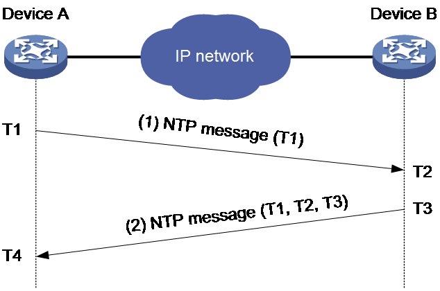
The synchronization process is as follows:
1. Device A sends to Device B an NTP request message, which is timestamped T1 when it leaves Device A.
2. Device B replies with an NTP response message, which carries:
¡ Timestamp T1.
¡ Timestamp T2 when the NTP request message arrived at Device B.
¡ Timestamp T2 when the NTP response message was sent from Device B.
3. Upon receiving the NTP response message, Device A records timestamp T4. Device A then get four timestamps T1, T2, T3, and T4 and can calculate the following parameters based on the timestamps:
¡ Roundtrip delay of the NTP message: Delay = (T4 – T1) – (T3 – T2).
¡ Time difference between Device A and Device B: Offset = [ (T2 – T1) + (T3 – T4) ] /2.
Based on these parameters, Device A can be synchronized to Device B.
This is only a rough description of the work mechanism of NTP. For more information, see the related protocols and standards.
NTP architecture
|
|
CAUTION: When the device acts as an NTP client, the NTP server's clock stratum must be not smaller than 0 and not larger than 14. If the NTP server's clock stratum is larger than 14, the device will not synchronize with that server's clock. You can log in to the NTP server to change its clock stratum by executing the ntp-service refclock-master command. · To check the stratum for an IPv4 NTP server, execute the display ntp-service sessions command on the device and check the stra field in the output. · To check the stratum for an IPv6 NTP server, execute the display ntp-service ipv6 sessions command on the device and check the Clock stratum field in the output. |
NTP network architecture
Figure 2 NTP network architecture
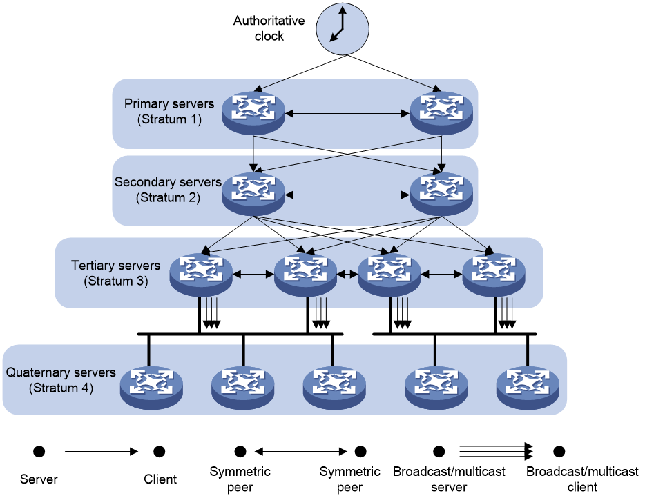
As shown in Figure 2, the NTP network is a hierarchical distributed system that contains multiple tiers of clocks to provide time synchronization services. This architecture helps reduce dependency on a single time source while providing redundancy and load balancing. The following are the key components of the NTP network:
· Stratum 0—The highest precision devices, such as atomic clocks, GPS, or radio clocks. They do not directly connect to the network but provide time to stratum 1 servers through wired or wireless connections.
· Stratum 1—Servers directly connected to stratum 0 devices. They act as primary time servers or reference clocks. Stratum 1 servers are typically used to provide precise time for public or private networks.
· Stratum 2—Servers connected to stratum 1 servers, receiving time from one or more stratum 1 servers and then providing time to lower-stratum servers or clients.
· Stratum 3 through stratum 15—Servers that receive time from servers of a higher stratum and that distribute this time down. Each stratum introduces some delay and jitter, but time synchronization accuracy can be achieved through complex algorithms and the use of multiple time sources.
If the devices in a network cannot synchronize to an authoritative time source, you can perform the following tasks:
· Select a device that has a relatively accurate clock from the network.
· Use the local clock of the device as the reference clock to synchronize other devices in the network.
NTP stratum
The NTP clock stratum represents the hierarchical level of an NTP server within the time synchronization structure. The stratum value is in the range of 1 to 15, with a larger value indicating a greater distance from the reference time source, which might result in reduced synchronization accuracy.
The clock stratum is typically determined automatically based on the upstream time source to which the server is connected. An NTP client only synchronizes with an NTP server whose clock stratum is less than or equal to its own, and the server’s stratum must be in the range of 0 to 14. Therefore, if you configure the device as an NTP server, you must set its clock stratum according to the network hierarchy.
NTP association modes
About NTP association modes
NTP supports the following association modes:
· Client/server mode
· Symmetric active/passive mode
· Broadcast mode
· Multicast mode
You can select one or more association modes for time synchronization. Table 1 provides detailed description for the four association modes. If the device acts as an NTP client and receives multiple NTP clock signals, it selects the optimal NTP clock for time synchronization.
In this document, an "NTP server" or a "server" refers to a device that operates as an NTP server in client/server mode. Time servers refer to all the devices that can provide time synchronization, including NTP servers, NTP symmetric peers, multicast servers, and broadcast servers.
|
Mode |
Synchronization direction |
Application scenario |
|
Client/server |
From the server to the client |
As Figure 2shown in the NTP architecture diagram in "NTP architecture," this mode is intended for for scenarios where devices with a higher stratum value obtain time from a device with a lower stratum value. You are required to specify the IP address of the NTP server on the client. |
|
Symmetric active/passive |
· If the symmetric peers are the same in the clock stratum, they can be synchronized to each other. · If the symmetric peers are different in the clock stratum, the peer with a smaller clock stratum will synchronize the clock of the peer with a greater clock stratum. |
As Figure 2shown in the NTP architecture diagram in "NTP architecture," this mode is most often used between servers with the same stratum to operate as a backup for one another. If a server fails to communicate with all the servers of a lower stratum, the server can still synchronize to the servers of the same stratum. You are required to specify the IP address of the symmetric passive peer on the symmetric active peer. |
|
Broadcast |
From the broadcast server to the client. |
A broadcast server sends clock synchronization messages to synchronize clients in the same subnet. As Figure 2shown in the NTP architecture diagram in "NTP architecture," broadcast mode is intended for configurations involving one or a few servers and a potentially large client population. The broadcast mode has lower time accuracy than the client/server and symmetric active/passive modes because only the broadcast servers send clock synchronization messages. |
|
Multicast |
From the multicast server to the client. |
A multicast server can provide time synchronization for clients in the same subnet or in different subnets. The multicast mode has lower time accuracy than the client/server and symmetric active/passive modes. |
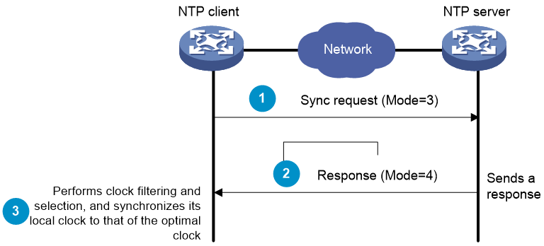
Operating mechanism for client/server association mode
NTP client/server mode allows an NTP server to maintain time information and allow NTP clients to communicate with the server to calibrate their clocks. In this mode, clients can accurately synchronize time with the server, ensuring time consistency across the network.
The time synchronization process in NTP client/server mode is as follows:
1. The client periodically sends time synchronization request messages to the server, with the mode field set to 3, indicating client mode. The client does not concern about the server's reachability or stratum.
2. Upon receiving the synchronization request from the client, the server fills the current time information in the response message and sets the mode field to 4, indicating server mode. Then, it sends the message back to the client. During this process, the server does not need to retain any state information about the client.
3. Upon receiving the response from the server, the client performs clock filtering and selection, and synchronizes its local clock to that of the optimal clock.
Figure 3 Operating mechanism for client/server association mode
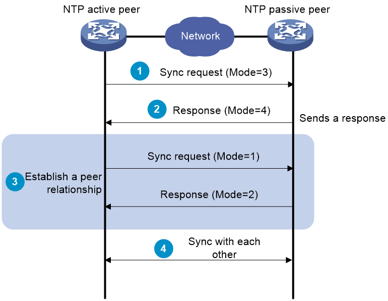
Operating mechanism for symmetric active/passive mode
In symmetric active/passive mode, time synchronization is implemented through communication and negotiation between two nodes (peers). Both peers can act as the time source, with the more reliable and accurate time from both nodes as the optimal time.
The time synchronization process in symmetric active/passive mode is as follows:
1. The symmetric active peer first sends a message with the mode field set to 1 (indicating an active peer), and the passive peer responds with a message with the mode field set to 2 (indicating a passive peer) to establish a peer relationship.
2. The peers send and receive time information for each other and use it to adjust their clocks. During this process, the two peers calculate the round-trip time delay and offset, and adjust their local clocks accordingly.
The peer with a smaller clock stratum will synchronize the clock of the peer with a greater clock stratum. The stratum indicates the distance from the standard time source. Nodes with a lower stratum are determined as closer to the standard time source, and therefore more reliable.
If the active peer can synchronize time with multiple time servers, it performs clock filtering and selection after receiving a response message. NTP uses a series of complex algorithms, such as clock filtering, offset prediction, and jitter estimation to select the best time sample and adjust the local time accordingly. Through these algorithms, the peers select the most stable and reliable time sample over a period as the basis for time synchronization.
Figure 4 Operating mechanism for symmetric active/passive mode
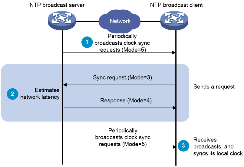
Operating mechanism for broadcast mode
NTP broadcast mode allows an NTP server to broadcast time information to the entire network. In this mode, any NTP clients listening to the broadcast can receive the time information and synchronize their system clocks accordingly.
The time synchronization process in NTP broadcast mode is as follows:
1. The broadcast server periodically sends clock synchronization request messages to broadcast address 255.255.255.255, with the mode field set to 5, indicating broadcast mode.
2. The broadcast client listens to the broadcast messages from the server. When the client receives the first broadcast message, the client and the server start to exchange messages to calculate the network delay between them.
3. The client enters broadcast mode, continues to listen for subsequent broadcast messages, and synchronizes its local clock based on the time information in these messages. Then, only the broadcast server sends clock synchronization messages.
Figure 5 Operating mechanism for broadcast mode
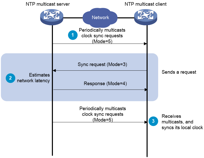
Operating mechanism for multicast mode
NTP multicast mode allows an NTP server to send time synchronization messages to user-configured IPv4 or IPv6 multicast addresses. A multicast server can provide time synchronization for clients in the same subnet or in different subnets. Only clients that have joined a multicast group can receive and process these messages.
The time synchronization process in NTP multicast mode is as follows:
1. The multicast server periodically sends clock synchronization request messages to the user-configured IPv4 or IPv6 multicast address, with the mode field set to 5, indicating multicast mode.
2. The broadcast client listens to the broadcast messages from the server. When the client receives the first broadcast message, the client and the server start to exchange messages to calculate the network delay between them.
3. The client enters multicast mode, continues to listen for subsequent multicast messages, and synchronizes its local clock based on the time information in these messages.
Figure 6 Operating mechanism for multicast mode
NTP security
To improve time synchronization security, NTP provides access control and authentication.
NTP access control
You can control NTP access by using an ACL. The access rights are in the following order, from the least restrictive to the most restrictive:
· Peer—Allows time requests and NTP control queries (such as alarms, authentication status, and time server information) and allows the local device to synchronize itself to a peer device.
· Server—Allows time requests and NTP control queries, but does not allow the local device to synchronize itself to a peer device.
· Synchronization—Allows only time requests from a system whose address passes the access list criteria.
· Query—Allows only NTP control queries from a peer device to the local device.
When the device acts as a client, specify the peer access right for it so that it can synchronize its time to a time server. When the device acts as a time server, specify the peer, server, or synchronization access right for it so that it can synchronize the time of its clients.
When the device receives an NTP request, it matches the request against the access rights in order from the least restrictive to the most restrictive: peer, server, synchronization, and query.
· If no NTP access control is configured, the peer access right applies.
· If the IP address of the peer device matches a permit statement in an ACL, the access right is granted to the peer device. If a deny statement or no ACL is matched, no access right is granted.
· If no ACL is specified for an access right or the ACL specified for the access right is not created, the access right is not granted.
· If none of the ACLs specified for the access rights is created, the peer access right applies.
· If none of the ACLs specified for the access rights contains rules, no access right is granted.
This feature provides minimal security for a system running NTP. A more secure method is NTP authentication.
NTP authentication
Use this feature to authenticate the NTP messages for security purposes. If an NTP message passes authentication, the device can receive it and get time synchronization information. If not, the device discards the message. This function makes sure the device does not synchronize to an unauthorized time server.
Figure 7 NTP authentication
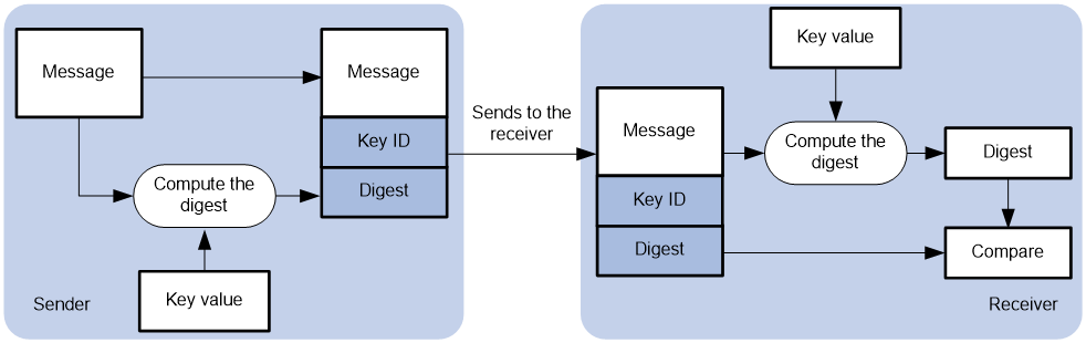
As shown in Figure 7, NTP authentication is performed as follows:
1. The sender uses the key identified by the key ID to calculate a digest for the NTP message through the MD5/HMAC authentication algorithm. Then it sends the calculated digest together with the NTP message and key ID to the receiver.
2. Upon receiving the message, the receiver performs the following actions:
a. Finds the key according to the key ID in the message.
b. Uses the key and the MD5/HMAC authentication algorithm to calculate the digest for the message.
c. Compares the digest with the digest contained in the NTP message.
- If they are different, the receiver discards the message.
- If they are the same, the local device determines whether the sender is allowed to use the authentication ID. If the sender is allowed to use the authentication ID, the receiver accepts the message. If the sender is not allowed to use the authentication ID, the receiver discards the message.
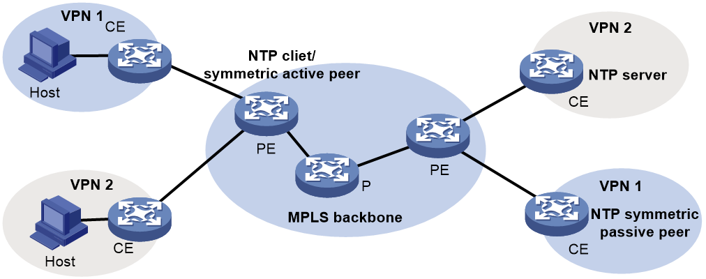
NTP for MPLS L3VPN instances
As shown in Figure 8, users in VPN 1 and VPN 2 are connected to the MPLS backbone network through provider edge (PE) devices. VPN instances vpn1 and vpn2 have been created for VPN 1 and VPN 2, respectively on the PEs. Services of the two VPN instances are isolated. Time synchronization between PEs and devices in the two VPN instances can be realized if you perform the following tasks:
· Configure the PEs to operate in NTP client or symmetric active mode.
· Specify the VPN instance to which the NTP server or NTP symmetric passive peer belongs.
For more information about MPLS L3VPN, VPN instance, and PE, see MPLS L3VPN configuration in MPLS Configuration Guide.
|
|
IMPORTANT: To synchronize the device time with devices in multiple MPLS L3VPN instances, you can configure NTP only in unicast mode rather than broadcast mode or multicast mode. |
Protocols and standards
· RFC 1305, Network Time Protocol (Version 3) Specification, Implementation and Analysis
· RFC 5905, Network Time Protocol Version 4: Protocol and Algorithms Specification
Restrictions and guidelines: NTP configuration
· You cannot configure both NTP and SNTP on the same device.
· NTP is supported only on the following Layer 3 interfaces:
¡ Layer 3 Ethernet interfaces.
¡ Layer 3 Ethernet subinterfaces.
¡ Layer 3 aggregate interfaces.
¡ Layer 3 aggregate subinterfaces.
¡ VLAN interfaces.
¡ Tunnel interfaces.
· Do not configure NTP settings on an aggregate member port.
· The NTP service and SNTP service are mutually exclusive. You can only enable either NTP service or SNTP service at a time.
· To avoid frequent time changes or even synchronization failures, do not specify more than one reference source on a network.
· For correct time synchronization, make sure the time offset between the system time and the NTP clock source is less than 68 years.
You must use the clock protocol command to specify NTP for obtaining the time. For more information about the clock protocol command, see device management commands in Fundamentals Command Reference.
|
|
CAUTION: When the device acts as an NTP client, the NTP server's clock stratum must be not smaller than 0 and not larger than 14. If the NTP server's clock stratum is larger than 14, the device will not synchronize with that server's clock. You can log in to the NTP server to change its clock stratum by executing the ntp-service refclock-master command. · To check the stratum for an IPv4 NTP server, execute the display ntp-service sessions command on the device and check the stra field in the output. · To check the stratum for an IPv6 NTP server, execute the display ntp-service ipv6 sessions command on the device and check the Clock stratum field in the output. |
Client/server mode tasks at a glance
Tasks on the client
By default, the NTP service is enabled. You do not need to perform this step.
2. (Optional.) Configuring high-precision NTP
3. Configuring NTP in client/server mode
4. (Optional.) Configuring the local clock as the reference source
5. (Optional.) Configuring access control rights
6. (Optional.) Configuring NTP authentication in client/server mode
7. (Optional.) Controlling NTP packet sending and receiving
¡ Specifying the source interface for NTP messages
¡ Disabling an interface from receiving NTP messages
¡ Configuring the maximum number of dynamic associations
¡ Setting a DSCP value for NTP packets
8. (Optional.) Specifying the NTP time-offset thresholds for log and trap outputs
Tasks on the server
By default, the NTP service is enabled. You do not need to perform this step.
2. (Optional.) Configuring high-precision NTP
3. Configuring NTP in client/server mode
You must enable the NTP server. By default, the NTP server is enabled. You do not need to perform this step.
4. (Optional.) Configuring the local clock as the reference source
5. (Optional.) Configuring access control rights
6. (Optional.) Configuring NTP authentication in client/server mode
7. (Optional.) Controlling NTP packet sending and receiving
¡ Specifying the source interface for NTP messages
¡ Disabling an interface from receiving NTP messages
¡ Configuring the maximum number of dynamic associations
¡ Setting a DSCP value for NTP packets
Symmetric active/passive mode tasks at a glance
Tasks on the active peer
By default, the NTP service is enabled. You do not need to perform this step.
2. Configuring NTP in symmetric active/passive mode
3. (Optional.) Configuring the local clock as the reference source
4. (Optional.) Configuring access control rights
5. (Optional.) Configuring NTP authentication in symmetric active/passive mode
6. (Optional.) Controlling NTP packet sending and receiving
¡ Specifying the source interface for NTP messages
¡ Disabling an interface from receiving NTP messages
¡ Configuring the maximum number of dynamic associations
¡ Setting a DSCP value for NTP packets
Tasks on the passive peer
By default, the NTP service is enabled. You do not need to perform this step.
2. (Optional.) Configuring the local clock as the reference source
3. (Optional.) Configuring access control rights
4. (Optional.) Configuring NTP authentication in symmetric active/passive mode
5. (Optional.) Controlling NTP packet sending and receiving
¡ Specifying the source interface for NTP messages
¡ Disabling an interface from receiving NTP messages
¡ Configuring the maximum number of dynamic associations
¡ Setting a DSCP value for NTP packets
6. (Optional.) Specifying the NTP time-offset thresholds for log and trap outputs
Broadcast mode tasks at a glance
Tasks on the client
By default, the NTP service is enabled. You do not need to perform this step.
2. Configuring NTP in broadcast mode
3. (Optional.) Configuring access control rights
4. (Optional.) Configuring NTP authentication in broadcast mode
5. (Optional.) Controlling NTP packet sending and receiving
¡ Specifying the source interface for NTP messages
¡ Disabling an interface from receiving NTP messages
¡ Configuring the maximum number of dynamic associations
¡ Setting a DSCP value for NTP packets
6. (Optional.) Specifying the NTP time-offset thresholds for log and trap outputs
Tasks on the server
By default, the NTP service is enabled. You do not need to perform this step.
2. Configuring NTP in broadcast mode
3. (Optional.) Configuring the local clock as the reference source
4. (Optional.) Configuring access control rights
5. (Optional.) Configuring NTP authentication in broadcast mode
6. (Optional.) Controlling NTP packet sending and receiving
¡ Specifying the source interface for NTP messages
¡ Disabling an interface from receiving NTP messages
¡ Configuring the maximum number of dynamic associations
¡ Setting a DSCP value for NTP packets
Multicast mode tasks at a glance
Tasks on the client
By default, the NTP service is enabled. You do not need to perform this step.
2. Configuring NTP in multicast mode
3. (Optional.) Configuring access control rights
4. (Optional.) Configuring NTP authentication in multicast mode
5. (Optional.) Controlling NTP packet sending and receiving
¡ Specifying the source interface for NTP messages
¡ Disabling an interface from receiving NTP messages
¡ Configuring the maximum number of dynamic associations
¡ Setting a DSCP value for NTP packets
6. (Optional.) Specifying the NTP time-offset thresholds for log and trap outputs
Tasks on the server
By default, the NTP service is enabled. You do not need to perform this step.
2. Configuring NTP in multicast mode
3. (Optional.) Configuring the local clock as the reference source
4. (Optional.) Configuring access control rights
5. (Optional.) Configuring NTP authentication in multicast mode
6. (Optional.) Controlling NTP packet sending and receiving
¡ Specifying the source interface for NTP messages
¡ Disabling an interface from receiving NTP messages
¡ Configuring the maximum number of dynamic associations
¡ Setting a DSCP value for NTP packets
Enabling the NTP service
Restrictions and guidelines
NTP and SNTP are mutually exclusive. Before you enable NTP, make sure SNTP is disabled.
Procedure
1. Enter system view.
system-view
2. Enable the NTP service.
ntp-service enable
By default, the NTP service is disabled.
Configuring high-precision NTP
About this task
Application scenarios
High-precision NTP offers more accurate time synchronization, meeting scenarios where NTP clients have higher time precision requirements.
Operating mechanism
When high-precision NTP is enabled on both an NTP client and NTP server, high-precision time synchronization can be achieved.
An NTP client sends a request to an NTP server at regular intervals to synchronize its clock, known as the poll interval. The poll interval might vary across different systems and configurations, and it can be dynamically adjusted based on network conditions and server load. Typically, in a stable network environment, an NTP client might send a request every 64 to 1024 seconds. In some cases, such as during initial startup or under unstable network conditions, the client and server might use shorter intervals for rapid time synchronization or resynchronization.
When the device operates as an NTP client and high-precision NTP is enabled on the device, the packet sending interval is at the millisecond level, enabling faster packet transmission speed.
When the device operates as an NTP server and high-precision NTP is enabled on the device, high-precision time synchronization can be implemented in collaboration with NTP clients.
High-precision NTP offers the following benefits:
· Faster time calibration—Shortening the poll interval allows for more frequent clock calibration, which is particularly crucial for systems requiring high-precision time synchronization, such as financial trading systems and scientific experiments.
· Faster initial synchronization—Shortening the polling interval allows the client to synchronize time with the NTP server more quickly after its first start or if it loses synchronization with the NTP server.
· Better resistance to network fluctuations—Network latency and jitter can affect the accuracy of clock synchronization. More frequent synchronization helps the system adapt more quickly to changes in these network conditions.
· More timely error correction—If the system clock skews quickly due to certain reasons (such as hardware issues), more frequent synchronization can help correct this deviation promptly.
Restrictions and guidelines
High-precision NTP takes effect only when it is enabled on both an NTP client and NTP server.
This feature takes effect only in client/server and symmetric peer modes. You can eanble high-precision NTP in broadcast and multicast modes, but the configuration does not take effect.
For high-precision NTP to take effect, do not enable NTP authentication, because high-precision NTP synchronizes time based on hardware and the device will switch back to software-based time synchronization after NTP authentication is enabled.
To enable high-precision NTP in symmetric peer mode, configure the ntp-service high-precision-time client enable and ntp-service high-precision-time server enable commands on both the symmetric-active and symmetric-passive peers, because bidirectional synchronization is used in symmetric peer mode.
This feature is not supported in an IRF network.
You cannot configure both high-precision NTP when PTP is enabled on the same device.
Configuring the NTP client
1. Enter system view.
system-view
2. Enable high-precision NTP client and set the polling interval.
ntp-service high-precision-time client enable [ poll-interval poll-interval-time ]
By default, high precision NTP client is disabled.
Configuring the NTP server
1. Enter system view.
system-view
2. Enable high-precision NTP server.
ntp-service high-precision-time server enable
By default, high-precision NTP server is disabled.
Configuring NTP association mode
Configuring NTP in client/server mode
Restrictions and guidelines
To configure NTP in client/server mode, specify an NTP server for the client.
For a client to synchronize to an NTP server, make sure the server is synchronized by other devices or uses its local clock as the reference source.
The stratum of an NTP server must be smaller than that of the client. If the stratum of a server is greater than or equal to a client, the client will not synchronize to that server.
You can specify multiple servers for a client by executing the ntp-service unicast-server or ntp-service ipv6 unicast-server command multiple times.
Configuring the NTP client
1. Enter system view.
system-view
2. Specify an NTP server for the device.
IPv4:
ntp-service unicast-server { server-name | ip-address } [ vpn-instance vpn-instance-name ] [ authentication-keyid keyid | priority | source interface-type interface-number | version number ] *
IPv6:
ntp-service ipv6 unicast-server { server-name | ipv6-address } [ vpn-instance vpn-instance-name ] [ authentication-keyid keyid | priority | source interface-type interface-number ] *
By default, no NTP server is specified.
As a best practice, specify the priority keyword in the configuration of only one server if you execute this command multiple times to configure multiple NTP servers. This prevents NTP from frequently switching between multiple NTP servers with the same priority when it selects the optimal clock source.
Configuring the NTP server
1. Enter system view.
system-view
2. Enable NTP server.
IPv4 network:
ntp-service time-server enable
By default, NTP server is enabled.
IPv6 network:
ntp-service ipv6 time-server enable
By default, IPv6 NTP server is enabled.
A device can provide NTP time synchronization to other devices only when it meets the following conditions:
¡ NTP server is enabled on the device.
¡ The device is permitted by the ACLs configured in the ntp-service acl or ntp-service ipv6 acl command on the other devices.
If you disable NTP server on the device, the device cannot provide NTP time synchronization to other devices.
Configuring NTP in symmetric active/passive mode
Restrictions and guidelines
To configure NTP in symmetric active/passive mode, specify a symmetric passive peer for the active peer.
For a symmetric passive peer to process NTP messages from a symmetric active peer, execute the ntp-service enable command on the symmetric passive peer to enable NTP.
For time synchronization between the symmetric active peer and the symmetric passive peer, make sure either or both of them are in synchronized state.
You can specify multiple symmetric passive peers by executing the ntp-service unicast-peer or ntp-service ipv6 unicast-peer command multiple times.
Procedure
1. Enter system view.
system-view
2. Specify a symmetric passive peer for the device.
IPv4:
ntp-service unicast-peer { peer-name | ip-address } [ vpn-instance vpn-instance-name ] [ authentication-keyid keyid | priority | source interface-type interface-number | version number ] *
IPv6:
ntp-service ipv6 unicast-peer { peer-name | ipv6-address } [ vpn-instance vpn-instance-name ] [ authentication-keyid keyid | priority | source interface-type interface-number ] *
By default, no symmetric passive peer is specified.
As a best practice, specify the priority keyword in the configuration of only one server if you execute this command multiple times to configure multiple NTP servers. This prevents NTP from frequently switching between multiple NTP servers with the same priority when it selects the optimal clock source.
3. Enable NTP server.
IPv4 network:
ntp-service time-server enable
By default, NTP server is enabled.
IPv6 network:
ntp-service ipv6 time-server enable
By default, IPv6 NTP server is enabled.
A device can provide NTP time synchronization to other devices only when it meets the following conditions:
¡ NTP server is enabled on the device.
¡ The device is permitted by the ACLs configured in the ntp-service acl or ntp-service ipv6 acl command on the other devices.
If you disable NTP server on the device, the device cannot provide NTP time synchronization to other devices.
Configuring NTP in broadcast mode
Restrictions and guidelines
To configure NTP in broadcast mode, you must configure an NTP broadcast client and an NTP broadcast server.
For a broadcast client to synchronize to a broadcast server, make sure the broadcast server is synchronized by other devices or uses its local clock as the reference source.
Configuring the broadcast client
1. Enter system view.
system-view
2. Enter interface view.
interface interface-type interface-number
3. Configure the device to operate in broadcast client mode.
ntp-service broadcast-client
By default, the device does not operate in any NTP association mode.
After you execute the command, the device receives NTP broadcast messages from the specified interface.
Configuring the broadcast server
1. Enter system view.
system-view
2. Enable NTP server.
IPv4 network:
ntp-service time-server enable
By default, NTP server is enabled.
IPv6 network:
ntp-service ipv6 time-server enable
By default, IPv6 NTP server is enabled.
A device can provide NTP time synchronization to other devices only when it meets the following conditions:
¡ NTP server is enabled on the device.
¡ The device is permitted by the ACLs configured in the ntp-service acl or ntp-service ipv6 acl command on the other devices.
If you disable NTP server on the device, the device cannot provide NTP time synchronization to other devices.
3. Enter interface view.
interface interface-type interface-number
4. Configure the device to operate in NTP broadcast server mode.
ntp-service broadcast-server [ authentication-keyid keyid | version number ] *
By default, the device does not operate in any NTP association mode.
After you execute the command, the device sends NTP broadcast messages from the specified interface.
Configuring NTP in multicast mode
Restrictions and guidelines
To configure NTP in multicast mode, you must configure an NTP multicast client and an NTP multicast server.
For a multicast client to synchronize to a multicast server, make sure the multicast server is synchronized by other devices or uses its local clock as the reference source.
Configuring a multicast client
1. Enter system view.
system-view
2. Enter interface view.
interface interface-type interface-number
3. Configure the device to operate in multicast client mode.
IPv4:
ntp-service multicast-client [ ip-address ]
IPv6:
ntp-service ipv6 multicast-client ipv6-address
By default, the device does not operate in any NTP association mode.
After you execute the command, the device receives NTP multicast messages from the specified interface.
Configuring the multicast server
1. Enter system view.
system-view
2. Enable NTP server.
IPv4 network:
ntp-service time-server enable
By default, NTP server is enabled.
IPv6 network:
ntp-service ipv6 time-server enable
By default, IPv6 NTP server is enabled.
A device can provide NTP time synchronization to other devices only when it meets the following conditions:
¡ NTP server is enabled on the device.
¡ The device is permitted by the ACLs configured in the ntp-service acl or ntp-service ipv6 acl command on the other devices.
If you disable NTP server on the device, the device cannot provide NTP time synchronization to other devices.
3. Enter interface view.
interface interface-type interface-number
4. Configure the device to operate in multicast server mode.
IPv4:
ntp-service multicast-server [ ip-address ] [ authentication-keyid keyid | ttl ttl-number | version number ] *
IPv6:
ntp-service ipv6 multicast-server ipv6-address [ authentication-keyid keyid | ttl ttl-number ] *
By default, the device does not operate in any NTP association mode.
After you execute the command, the device sends NTP multicast messages from the specified interface.
Configuring the local clock as the reference source
About this task
The clock stratum of an NTP server that obtains time synchronization from an authoritative clock (such as an atomic clock) is typically set to 1 and used as the primary time server to synchronize the clocks of other devices in the network. The NTP distance between devices and the primary time server in the network, which is the number of servers in the NTP synchronization chain, determines the stratum of the device clocks.
If the devices in a network cannot synchronize to an authoritative time source, you can perform the following tasks:
· Select a device that has a relatively accurate clock from the network.
· Use the local clock of the device as the reference clock to synchronize other devices in the network.
Restrictions and guidelines
Make sure the local clock can provide the time accuracy required for the network. After you configure the local clock as the reference source, the local clock is synchronized, and can operate as a time server to synchronize other devices in the network. If the local clock is incorrect, timing errors occur.
The system time reverts to the initial BIOS default after a cold reboot. As a best practice, do not configure the local clock as the reference source or configure the device as a time server.
Devices differ in clock precision. As a best practice to avoid network flapping and clock synchronization failure, configure only one reference clock on the same network segment and make sure the clock has high precision.
Prerequisites
Before you configure this feature, adjust the local system time to ensure that it is accurate.
Procedure
1. Enter system view.
system-view
2. Configure the local clock as the reference source.
ntp-service refclock-master [ ip-address ] [ stratum ]
By default, the device does not use the local clock as the reference source.
Configuring access control rights
Prerequisites
Before you configure the right for peer devices to access the NTP services on the local device, create and configure ACLs associated with the access right. For information about configuring an ACL, see ACL and QoS Configuration Guide.
Restrictions and guidelines
Follow the restrictions and guidelines as described in Table 2 to configure the NTP access control rights.
Table 2 Restrictions and guidelines for configuring NTP access control rights
|
NTP access control right |
Whether the time can be synchronized (whether configurable on a client) |
Whether can synchronize the time of other devices (whether configurable on a time server) |
Whether control queries are allowed |
|
Peer |
Yes |
Yes |
Yes |
|
Server |
Yes |
No |
Yes |
|
Synchronization |
Yes |
No |
No |
|
Query |
No |
No |
Yes |
The ntp-service noquery enable command and its undo form are used only to configure the device to disallow or allow control queries and do not disable or enable clock synchronization. If the ntp-service noquery enable command or its undo form and the ntp-service acl or ntp-service ipv6 acl command are both configured, the ntp-service noquery enable command or its undo form determines whether control queries are allowed.
Procedure
1. Enter system view.
system-view
2. Configure the right for peer devices to access the NTP services on the local device.
IPv4:
ntp-service { peer | query | server | synchronization } acl { ipv4-acl-number | name ipv4-acl-name }
IPv6:
ntp-service ipv6 { peer | query | server | synchronization } acl { ipv6-acl-number | name ipv6-acl-name }
By default, the right for peer devices to access the NTP services on the local device is peer.
3. Disallow control queries for the local device.
ntp-service noquery enable
By default, control queries for the local device are allowed.
Configuring NTP authentication
Configuring NTP authentication in client/server mode
Restrictions and guidelines
To ensure a successful NTP authentication in client/server mode, configure the same authentication key ID, algorithm, and key on the server and client. Make sure the peer device is allowed to use the key ID for authentication on the local device.
NTP authentication results differ when different configurations are performed on client and server. For more information, see Table 3. (N/A in the table means that whether the configuration is performed or not does not make any difference.)
Table 3 NTP authentication results
|
Client |
Server |
|||
|
Enable NTP authentication |
Specify the server and key |
Trusted key |
Enable NTP authentication |
Trusted key |
|
Successful authentication |
||||
|
Yes |
Yes |
Yes |
Yes |
Yes |
|
Failed authentication |
||||
|
Yes |
Yes |
Yes |
Yes |
No |
|
Yes |
Yes |
Yes |
No |
N/A |
|
Yes |
Yes |
No |
N/A |
N/A |
|
Authentication not performed |
||||
|
Yes |
No |
N/A |
N/A |
N/A |
|
No |
N/A |
N/A |
N/A |
N/A |
Configuring NTP authentication for a client
1. Enter system view.
system-view
2. Enable NTP authentication.
ntp-service authentication enable
By default, NTP authentication is disabled.
3. Configure an NTP authentication key.
ntp-service authentication-keyid keyid authentication-mode { hmac-sha-1 | hmac-sha-256 | hmac-sha-384 | hmac-sha-512 | md5 } { cipher | simple } string [ acl ipv4-acl-number | ipv6 acl ipv6-acl-number ] *
By default, no NTP authentication key exists.
4. Configure the key as a trusted key.
ntp-service reliable authentication-keyid keyid
By default, no authentication key is configured as a trusted key.
5. Associate the specified key with an NTP server.
IPv4:
ntp-service unicast-server { server-name | ip-address } [ vpn-instance vpn-instance-name ] authentication-keyid keyid
IPv6:
ntp-service ipv6 unicast-server { server-name | ipv6-address } [ vpn-instance vpn-instance-name ] authentication-keyid keyid
Configuring NTP authentication for a server
1. Enter system view.
system-view
2. Enable NTP authentication.
ntp-service authentication enable
By default, NTP authentication is disabled.
3. Configure an NTP authentication key.
ntp-service authentication-keyid keyid authentication-mode { hmac-sha-1 | hmac-sha-256 | hmac-sha-384 | hmac-sha-512 | md5 } { cipher | simple } string [ acl ipv4-acl-number | ipv6 acl ipv6-acl-number ] *
By default, no NTP authentication key exists.
4. Configure the key as a trusted key.
ntp-service reliable authentication-keyid keyid
By default, no authentication key is configured as a trusted key.
Configuring NTP authentication in symmetric active/passive mode
Restrictions and guidelines
To ensure a successful NTP authentication in symmetric active/passive mode, configure the same authentication key ID, algorithm, and key on the active peer and passive peer. Make sure the peer device is allowed to use the key ID for authentication on the local device.
NTP authentication results differ when different configurations are performed on active peer and passive peer. For more information, see Table 4. (N/A in the table means that whether the configuration is performed or not does not make any difference.)
Table 4 NTP authentication results
|
Active peer |
Passive peer |
||||
|
Enable NTP authentication |
Specify the peer and key |
Trusted key |
Stratum level |
Enable NTP authentication |
Trusted key |
|
Successful authentication |
|||||
|
Yes |
Yes |
Yes |
N/A |
Yes |
Yes |
|
Failed authentication |
|||||
|
Yes |
Yes |
Yes |
N/A |
Yes |
No |
|
Yes |
Yes |
Yes |
N/A |
No |
N/A |
|
Yes |
No |
N/A |
N/A |
Yes |
N/A |
|
No |
N/A |
N/A |
N/A |
Yes |
N/A |
|
Yes |
Yes |
No |
Larger than the passive peer |
N/A |
N/A |
|
Yes |
Yes |
No |
Smaller than the passive peer |
Yes |
N/A |
|
Authentication not performed |
|||||
|
Yes |
No |
N/A |
N/A |
No |
N/A |
|
No |
N/A |
N/A |
N/A |
No |
N/A |
|
Yes |
Yes |
No |
Smaller than the passive peer |
No |
N/A |
Configuring NTP authentication for an active peer
1. Enter system view.
system-view
2. Enable NTP authentication.
ntp-service authentication enable
By default, NTP authentication is disabled.
3. Configure an NTP authentication key.
ntp-service authentication-keyid keyid authentication-mode { hmac-sha-1 | hmac-sha-256 | hmac-sha-384 | hmac-sha-512 | md5 } { cipher | simple } string [ acl ipv4-acl-number | ipv6 acl ipv6-acl-number ] *
By default, no NTP authentication key exists.
4. Configure the key as a trusted key.
ntp-service reliable authentication-keyid keyid
By default, no authentication key is configured as a trusted key.
5. Associate the specified key with a passive peer.
IPv4:
ntp-service unicast-peer { ip-address | peer-name } [ vpn-instance vpn-instance-name ] authentication-keyid keyid
IPv6:
ntp-service ipv6 unicast-peer { ipv6-address | peer-name } [ vpn-instance vpn-instance-name ] authentication-keyid keyid
Configuring NTP authentication for a passive peer
1. Enter system view.
system-view
2. Enable NTP authentication.
ntp-service authentication enable
By default, NTP authentication is disabled.
3. Configure an NTP authentication key.
ntp-service authentication-keyid keyid authentication-mode { hmac-sha-1 | hmac-sha-256 | hmac-sha-384 | hmac-sha-512 | md5 } { cipher | simple } string [ acl ipv4-acl-number | ipv6 acl ipv6-acl-number ] *
By default, no NTP authentication key exists.
4. Configure the key as a trusted key.
ntp-service reliable authentication-keyid keyid
By default, no authentication key is configured as a trusted key.
Configuring NTP authentication in broadcast mode
Restrictions and guidelines
To ensure a successful NTP authentication in broadcast mode, configure the same authentication key ID, algorithm, and key on the broadcast server and client. Make sure the peer device is allowed to use the key ID for authentication on the local device.
NTP authentication results differ when different configurations are performed on broadcast client and server. For more information, see Table 5. (N/A in the table means that whether the configuration is performed or not does not make any difference.)
Table 5 NTP authentication results
|
Broadcast server |
Broadcast client |
|||
|
Enable NTP authentication |
Specify the server and key |
Trusted key |
Enable NTP authentication |
Trusted key |
|
Successful authentication |
||||
|
Yes |
Yes |
Yes |
Yes |
Yes |
|
Failed authentication |
||||
|
Yes |
Yes |
Yes |
Yes |
No |
|
Yes |
Yes |
Yes |
No |
N/A |
|
Yes |
Yes |
No |
Yes |
N/A |
|
Yes |
No |
N/A |
Yes |
N/A |
|
No |
N/A |
N/A |
Yes |
N/A |
|
Authentication not performed |
||||
|
Yes |
Yes |
No |
No |
N/A |
|
Yes |
No |
N/A |
No |
N/A |
|
No |
N/A |
N/A |
No |
N/A |
Configuring NTP authentication for a broadcast client
1. Enter system view.
system-view
2. Enable NTP authentication.
ntp-service authentication enable
By default, NTP authentication is disabled.
3. Configure an NTP authentication key.
ntp-service authentication-keyid keyid authentication-mode { hmac-sha-1 | hmac-sha-256 | hmac-sha-384 | hmac-sha-512 | md5 } { cipher | simple } string [ acl ipv4-acl-number | ipv6 acl ipv6-acl-number ] *
By default, no NTP authentication key exists.
4. Configure the key as a trusted key.
ntp-service reliable authentication-keyid keyid
By default, no authentication key is configured as a trusted key.
Configuring NTP authentication for a broadcast server
1. Enter system view.
system-view
2. Enable NTP authentication.
ntp-service authentication enable
By default, NTP authentication is disabled.
3. Configure an NTP authentication key.
ntp-service authentication-keyid keyid authentication-mode { hmac-sha-1 | hmac-sha-256 | hmac-sha-384 | hmac-sha-512 | md5 } { cipher | simple } string [ acl ipv4-acl-number | ipv6 acl ipv6-acl-number ] *
By default, no NTP authentication key exists.
4. Configure the key as a trusted key.
ntp-service reliable authentication-keyid keyid
By default, no authentication key is configured as a trusted key.
5. Enter interface view.
interface interface-type interface-number
6. Associate the specified key with the broadcast server.
ntp-service broadcast-server authentication-keyid keyid
By default, the broadcast server is not associated with a key.
Configuring NTP authentication in multicast mode
Restrictions and guidelines
To ensure a successful NTP authentication in multicast mode, configure the same authentication key ID, algorithm, and key on the multicast server and client. Make sure the peer device is allowed to use the key ID for authentication on the local device.
NTP authentication results differ when different configurations are performed on broadcast client and server. For more information, see Table 6. (N/A in the table means that whether the configuration is performed or not does not make any difference.)
Table 6 NTP authentication results
|
Multicast server |
Multicast client |
|||
|
Enable NTP authentication |
Specify the server and key |
Trusted key |
Enable NTP authentication |
Trusted key |
|
Successful authentication |
||||
|
Yes |
Yes |
Yes |
Yes |
Yes |
|
Failed authentication |
||||
|
Yes |
Yes |
Yes |
Yes |
No |
|
Yes |
Yes |
Yes |
No |
N/A |
|
Yes |
Yes |
No |
Yes |
N/A |
|
Yes |
No |
N/A |
Yes |
N/A |
|
No |
N/A |
N/A |
Yes |
N/A |
|
Authentication not performed |
||||
|
Yes |
Yes |
No |
No |
N/A |
|
Yes |
No |
N/A |
No |
N/A |
|
No |
N/A |
N/A |
No |
N/A |
Configuring NTP authentication for a multicast client
1. Enter system view.
system-view
2. Enable NTP authentication.
ntp-service authentication enable
By default, NTP authentication is disabled.
3. Configure an NTP authentication key.
ntp-service authentication-keyid keyid authentication-mode { hmac-sha-1 | hmac-sha-256 | hmac-sha-384 | hmac-sha-512 | md5 } { cipher | simple } string [ acl ipv4-acl-number | ipv6 acl ipv6-acl-number ] *
By default, no NTP authentication key exists.
4. Configure the key as a trusted key.
ntp-service reliable authentication-keyid keyid
By default, no authentication key is configured as a trusted key.
Configuring NTP authentication for a multicast server
1. Enter system view.
system-view
2. Enable NTP authentication.
ntp-service authentication enable
By default, NTP authentication is disabled.
3. Configure an NTP authentication key.
ntp-service authentication-keyid keyid authentication-mode { hmac-sha-1 | hmac-sha-256 | hmac-sha-384 | hmac-sha-512 | md5 } { cipher | simple } string [ acl ipv4-acl-number | ipv6 acl ipv6-acl-number ] *
By default, no NTP authentication key exists.
4. Configure the key as a trusted key.
ntp-service reliable authentication-keyid keyid
By default, no authentication key is configured as a trusted key.
5. Enter interface view.
interface interface-type interface-number
6. Associate the specified key with a multicast server.
IPv4:
ntp-service multicast-server [ ip-address ] authentication-keyid keyid
IPv6:
ntp-service ipv6 multicast-server ipv6-address authentication-keyid keyid
By default, no multicast server is associated with the specified key.
Controlling NTP packet sending and receiving
Specifying the source interface for NTP messages
Restrictions and guidelines
To prevent interface status changes from causing NTP communication failures, configure the device to use the IP address of an interface that is always up. For example, you can configure the device to use a loopback interface as the source IP address for the NTP messages to be sent.
When the device responds to an NTP request, the source IP address of the NTP response is always the IP address of the interface that has received the NTP request.
If you have specified the source interface for NTP messages in the ntp-service unicast-server/ntp-service ipv6 unicast-server or ntp-service unicast-peer/ntp-service ipv6 unicast-peer command, the specified interface is the source interface for NTP messages.
If you have configured the ntp-service broadcast-server or ntp-service multicast-server/ntp-service ipv6 multicast-server command in an interface view, this interface acts as the source interface for broadcast or multicast NTP messages.
Procedure
1. Enter system view.
system-view
2. Specify the source interface for NTP packets.
IPv4:
ntp-service source interface-type interface-number
IPv6:
ntp-service ipv6 source interface-type interface-number
By default, no source interface is specified for NTP messages.
Disabling an interface from receiving NTP messages
About this task
When NTP is enabled, all interfaces by default can receive NTP messages. For security purposes, you can disable some of the interfaces from receiving NTP messages.
Procedure
1. Enter system view.
system-view
2. Enter interface view.
interface interface-type interface-number
3. Disable the interface from receiving NTP packets.
IPv4:
undo ntp-service inbound enable
IPv6:
undo ntp-service ipv6 inbound enable
By default, an interface receives NTP messages.
Configuring the maximum number of dynamic associations
About this task
Perform this task to restrict the number of dynamic associations to prevent dynamic associations from occupying too many system resources.
NTP has the following types of associations:
· Static association—A manually created association.
· Dynamic association—Temporary association created by the system during NTP operation. A dynamic association is removed if no messages are exchanged within about 12 minutes.
The following describes how an association is established in different association modes:
· Client/server mode—After you specify an NTP server, the system creates a static association on the client. The server simply responds passively upon the receipt of a message, rather than creating an association (static or dynamic).
· Symmetric active/passive mode—After you specify a symmetric passive peer on a symmetric active peer, static associations are created on the symmetric active peer, and dynamic associations are created on the symmetric passive peer.
· Broadcast or multicast mode—Static associations are created on the server, and dynamic associations are created on the client.
Restrictions and guidelines
A single device can have a maximum of 128 concurrent associations, including static associations and dynamic associations.
The ntp-service max-dynamic-sessions command does not affect existing NTP associations. After this command is configured, new associations will not be established if the maximum number of associations has been reached or exceeded.
Procedure
1. Enter system view.
system-view
2. Configure the maximum number of dynamic sessions.
ntp-service max-dynamic-sessions number
By default, the maximum number of dynamic sessions is 100.
Setting a DSCP value for NTP packets
About this task
The DSCP value determines the sending precedence of an NTP packet.
Procedure
1. Enter system view.
system-view
2. Set a DSCP value for NTP packets.
IPv4:
ntp-service dscp dscp-value
IPv6:
ntp-service ipv6 dscp dscp-value
The default DSCP value is 48 for IPv4 packets and 56 for IPv6 packets.
Specifying the NTP time-offset thresholds for log and trap outputs
About this task
By default, the NTP client synchronizes the time with the server and outputs a log and a trap when the time offset between the client and server exceeds 128 ms for multiple times.
After you set the NTP time-offset thresholds for log and trap outputs, the NTP client synchronizes the time with the server when the time offset exceeds 128 ms for multiple times, but outputs a log or trap only when the time offset exceeds the specified threshold.
Procedure
1. Enter system view.
system-view
2. Specify the NTP time-offset thresholds for log and trap outputs.
ntp-service time-offset-threshold { log log-threshold | trap trap-threshold } *
By default, no NTP time-offset thresholds are set for log and trap outputs.
Display and maintenance commands for NTP
The ntp-service noquery enable command is mutually exclusive with the display ntp-service trace command. To use the display ntp-service trace command, you must configure the device to allow control queries.
Execute display commands in any view.
|
Task |
Command |
|
Display session information for high-precision NTP. |
display ntp-service high-precision-time session |
|
Display status information for high-precision NTP. |
display ntp-service high-precision-time status |
|
Display information about IPv6 NTP associations. |
display ntp-service ipv6 sessions [ verbose ] |
|
Display information about IPv4 NTP associations. |
display ntp-service sessions [ verbose ] |
|
Display information about NTP service status. |
display ntp-service status |
|
Display brief information about the NTP servers from the local device back to the primary NTP server. |
display ntp-service trace [ source interface-type interface-number ] |
NTP configuration examples
Example: Configuring NTP client/server association mode
Network configuration
As shown in Figure 9, perform the following tasks:
· Configure Device A's local clock as its reference source, with stratum level 2.
· Configure Device B to operate in client mode and specify Device A as the NTP server of Device B.

Procedure
1. Assign an IP address to each interface, and make sure Device A and Device B can reach each other, as shown in Figure 9. (Details not shown.)
2. Configure Device A:
# Enable the NTP service.
<DeviceA> system-view
[DeviceA] ntp-service enable
# Specify the local clock as the reference source, with stratum level 2.
[DeviceA] ntp-service refclock-master 2
3. Configure Device B:
# Enable the NTP service.
<DeviceB> system-view
[DeviceB] ntp-service enable
# Specify NTP for obtaining the time.
[DeviceB] clock protocol ntp
# Specify Device A as the NTP server of Device B.
[DeviceB] ntp-service unicast-server 1.0.1.11
Verifying the configuration
# Verify that Device B has synchronized its time with Device A, and the clock stratum level of Device B is 3.
[DeviceB] display ntp-service status
Clock status: synchronized
Clock stratum: 3
System peer: 1.0.1.11
Local mode: client
Reference clock ID: 1.0.1.11
Leap indicator: 00
Clock jitter: 0.000977 s
Stability: 0.000 pps
Clock precision: 2^-18
Root delay: 0.00383 ms
Root dispersion: 16.26572 ms
Reference time: d0c6033f.b9923965 Wed, Dec 29 2010 18:58:07.724
Sync state from NTP server to local clock: clock synced
# Verify that an IPv4 NTP association has been established between Device B and Device A.
[DeviceB] display ntp-service sessions
source reference stra reach poll now offset delay disper
********************************************************************************
[12345]1.0.1.11 127.127.1.0 2 1 64 15 -4.0 0.0038 16.262
Notes: 1 source(master), 2 source(peer), 3 selected, 4 candidate, 5 configured.
Total sessions: 1
Example: Configuring IPv6 NTP client/server association mode
Network configuration
As shown in Figure 10, perform the following tasks:
· Configure Device A's local clock as its reference source, with stratum level 2.
· Configure Device B to operate in client mode and specify Device A as the IPv6 NTP server of Device B.

Procedure
1. Assign an IP address to each interface, and make sure Device A and Device B can reach each other, as shown in Figure 10. (Details not shown.)
2. Configure Device A:
# Enable the NTP service.
<DeviceA> system-view
[DeviceA] ntp-service enable
# Specify the local clock as the reference source, with stratum level 2.
[DeviceA] ntp-service refclock-master 2
3. Configure Device B:
# Enable the NTP service.
<DeviceB> system-view
[DeviceB] ntp-service enable
# Specify NTP for obtaining the time.
[DeviceB] clock protocol ntp
# Specify Device A as the IPv6 NTP server of Device B.
[DeviceB] ntp-service ipv6 unicast-server 3000::34
Verifying the configuration
# Verify that Device B has synchronized its time with Device A, and the clock stratum level of Device B is 3.
[DeviceB] display ntp-service status
Clock status: synchronized
Clock stratum: 3
System peer: 3000::34
Local mode: client
Reference clock ID: 163.29.247.19
Leap indicator: 00
Clock jitter: 0.000977 s
Stability: 0.000 pps
Clock precision: 2^-18
Root delay: 0.02649 ms
Root dispersion: 12.24641 ms
Reference time: d0c60419.9952fb3e Wed, Dec 29 2010 19:01:45.598
Sync state from NTP server to local clock: clock synced
# Verify that an IPv6 NTP association has been established between Device B and Device A.
[DeviceB] display ntp-service ipv6 sessions
Notes: 1 source(master), 2 source(peer), 3 selected, 4 candidate, 5 configured.
Source: [12345]3000::34
Reference: 127.127.1.0 Clock stratum: 2
Reachabilities: 15 Poll interval: 64
Last receive time: 19 Offset: 0.0
Roundtrip delay: 0.0 Dispersion: 0.0
Total sessions: 1
Example: Configuring NTP symmetric active/passive association mode
Network configuration
As shown in Figure 11, perform the following tasks:
· Configure Device A's local clock as its reference source, with stratum level 2.
· Configure Device A to operate in symmetric active mode and specify Device B as the passive peer of Device A.

Procedure
1. Assign an IP address to each interface, and make sure Device A and Device B can reach each other, as shown in Figure 11. (Details not shown.)
2. Configure Device B:
# Enable the NTP service.
<DeviceB> system-view
[DeviceA] ntp-service enable
# Specify NTP for obtaining the time.
[DeviceB] clock protocol ntp
3. Configure Device A:
# Enable the NTP service.
<DeviceA> system-view
[DeviceB] ntp-service enable
# Specify NTP for obtaining the time.
[DeviceA] clock protocol ntp
# Specify the local clock as the reference source, with stratum level 2.
[DeviceA] ntp-service refclock-master 2
# Configure Device B as its symmetric passive peer.
[DeviceA] ntp-service unicast-peer 3.0.1.32
Verifying the configuration
# Verify that Device B has synchronized its time with Device A.
[DeviceB] display ntp-service status
Clock status: synchronized
Clock stratum: 3
System peer: 3.0.1.31
Local mode: sym_passive
Reference clock ID: 3.0.1.31
Leap indicator: 00
Clock jitter: 0.000916 s
Stability: 0.000 pps
Clock precision: 2^-17
Root delay: 0.00609 ms
Root dispersion: 1.95859 ms
Reference time: 83aec681.deb6d3e5 Wed, Jan 8 2014 14:33:11.081
Sync state from NTP server to local clock: clock synced
# Verify that an IPv4 NTP association has been established between Device B and Device A.
[DeviceB] display ntp-service sessions
source reference stra reach poll now offset delay disper
********************************************************************************
[12]3.0.1.31 127.127.1.0 2 62 64 34 0.4251 6.0882 1392.1
Notes: 1 source(master), 2 source(peer), 3 selected, 4 candidate, 5 configured.
Total sessions: 1
Example: Configuring IPv6 NTP symmetric active/passive association mode
Network configuration
As shown in Figure 12, perform the following tasks:
· Configure Device A's local clock as its reference source, with stratum level 2.
· Configure Device A to operate in symmetric active mode and specify Device B as the IPv6 passive peer of Device A.

Procedure
1. Assign an IP address to each interface, and make sure Device A and Device B can reach each other, as shown in Figure 12. (Details not shown.)
2. Configure Device B:
# Enable the NTP service.
<DeviceB> system-view
[DeviceB] ntp-service enable
# Specify NTP for obtaining the time.
[DeviceB] clock protocol ntp
3. Configure Device A:
# Enable the NTP service.
<DeviceA> system-view
[DeviceA] ntp-service enable
# Specify NTP for obtaining the time.
[DeviceA] clock protocol ntp
# Specify the local clock as the reference source, with stratum level 2.
[DeviceA] ntp-service refclock-master 2
# Configure Device B as the IPv6 symmetric passive peer.
[DeviceA] ntp-service ipv6 unicast-peer 3000::36
Verifying the configuration
# Verify that Device B has synchronized its time with Device A.
[DeviceB] display ntp-service status
Clock status: synchronized
Clock stratum: 3
System peer: 3000::35
Local mode: sym_passive
Reference clock ID: 251.73.79.32
Leap indicator: 11
Clock jitter: 0.000977 s
Stability: 0.000 pps
Clock precision: 2^-10
Root delay: 0.01855 ms
Root dispersion: 9.23483 ms
Reference time: d0c6047c.97199f9f Wed, Dec 29 2010 19:03:24.590
Sync state from NTP server to local clock: clock synced
# Verify that an IPv6 NTP association has been established between Device B and Device A.
[DeviceB] display ntp-service ipv6 sessions
Notes: 1 source(master), 2 source(peer), 3 selected, 4 candidate, 5 configured.
Source: [1234]3000::35
Reference: 127.127.1.0 Clock stratum: 2
Reachabilities: 15 Poll interval: 64
Last receive time: 19 Offset: 0.0
Roundtrip delay: 0.0 Dispersion: 0.0
Total sessions: 1
Example: Configuring NTP authentication in client/server association mode
Network configuration
As shown in Figure 13, perform the following tasks:
· Configure Device A's local clock as its reference source, with stratum level 2.
· Configure Device B to operate in client mode and specify Device A as the NTP server of Device B.
· Configure NTP authentication on both Device A and Device B.

Procedure
1. Assign an IP address to each interface, and make sure Device A and Device B can reach each other, as shown in Figure 13. (Details not shown.)
2. Configure Device A:
# Enable the NTP service.
<DeviceA> system-view
[DeviceA] ntp-service enable
# Specify the local clock as the reference source, with stratum level 2.
[DeviceA] ntp-service refclock-master 2
3. Configure Device B:
# Enable the NTP service.
<DeviceB> system-view
[DeviceB] ntp-service enable
# Specify NTP for obtaining the time.
[DeviceB] clock protocol ntp
# Enable NTP authentication on Device B.
[DeviceB] ntp-service authentication enable
# Create a plaintext authentication key, with key ID 42 and key value aNiceKey.
[DeviceB] ntp-service authentication-keyid 42 authentication-mode md5 simple aNiceKey
# Specify the key as a trusted key.
[DeviceB] ntp-service reliable authentication-keyid 42
# Specify Device A as the NTP server of Device B, and associate the server with key 42.
[DeviceB] ntp-service unicast-server 1.0.1.11 authentication-keyid 42
To enable Device B to synchronize its clock with Device A, enable NTP authentication on Device A.
4. Configure NTP authentication on Device A:
# Enable NTP authentication.
[DeviceA] ntp-service authentication enable
# Create a plaintext authentication key, with key ID 42 and key value aNiceKey.
[DeviceA] ntp-service authentication-keyid 42 authentication-mode md5 simple aNiceKey
# Specify the key as a trusted key.
[DeviceA] ntp-service reliable authentication-keyid 42
Verifying the configuration
# Verify that Device B has synchronized its time with Device A, and the clock stratum level of Device B is 3.
[DeviceB] display ntp-service status
Clock status: synchronized
Clock stratum: 3
System peer: 1.0.1.11
Local mode: client
Reference clock ID: 1.0.1.11
Leap indicator: 00
Clock jitter: 0.005096 s
Stability: 0.000 pps
Clock precision: 2^-10
Root delay: 0.00655 ms
Root dispersion: 1.15869 ms
Reference time: d0c62687.ab1bba7d Wed, Dec 29 2010 21:28:39.668
Sync state from NTP server to local clock: clock synced
# Verify that an IPv4 NTP association has been established between Device B and Device A.
[DeviceB] display ntp-service sessions
source reference stra reach poll now offset delay disper
********************************************************************************
[1245]1.0.1.11 127.127.1.0 2 1 64 519 -0.0 0.0065 0.0
Notes: 1 source(master),2 source(peer),3 selected,4 candidate,5 configured.
Total sessions: 1
Example: Configuring NTP broadcast association mode
Network configuration
As shown in Figure 14, configure Router C as the NTP server of multiple devices on the same network segment so that these devices synchronize the time with Router C.
· Configure Router C's local clock as its reference source, with stratum level 2.
· Configure Router C to operate in broadcast server mode and send broadcast messages from Ten-GigabitEthernet 0/0/15.
· Configure Router B and Router A to operate in broadcast client mode and receive broadcast messages on Ten-GigabitEthernet 0/0/15.

Procedure
1. Assign an IP address to each interface, and make sure Router A, Router B, and Router C can reach each other, as shown in Figure 14. (Details not shown.)
2. Configure Router C:
# Enable the NTP service.
<RouterC> system-view
[RouterC] ntp-service enable
# Specify NTP for obtaining the time.
[RouterC] clock protocol ntp
# Specify the local clock as the reference source, with stratum level 2.
[RouterC] ntp-service refclock-master 2
# Configure Router C to operate in broadcast server mode and send broadcast messages from Ten-GigabitEthernet 0/0/15.
[RouterC] interface ten-gigabitethernet 0/0/15
[RouterC-Ten-GigabitEthernet0/0/15] ntp-service broadcast-server
[RouterC-Ten-GigabitEthernet0/0/15] quit
3. Configure Router A:
# Enable the NTP service.
<RouterA> system-view
[RouterA] ntp-service enable
# Specify NTP for obtaining the time.
[RouterA] clock protocol ntp
# Configure Router A to operate in broadcast client mode and receive broadcast messages on Ten-GigabitEthernet 0/0/15.
[RouterA] interface ten-gigabitethernet 0/0/15
[RouterA-Ten-GigabitEthernet0/0/15] ntp-service broadcast-client
[RouterA-Ten-GigabitEthernet0/0/15] quit
4. Configure Router B:
# Enable the NTP service.
<RouterB> system-view
[RouterB] ntp-service enable
# Specify NTP for obtaining the time.
[RouterB] clock protocol ntp
# Configure Router B to operate in broadcast client mode and receive broadcast messages on Ten-GigabitEthernet 0/0/15.
[RouterB] interface ten-gigabitethernet 0/0/15
[RouterB-Ten-GigabitEthernet0/0/15] ntp-service broadcast-client
[RouterB-Ten-GigabitEthernet0/0/15] quit
Verifying the configuration
The following procedure uses Router A as an example to verify the configuration.
# Verify that Router A has synchronized its time with Router C, and the clock stratum level of Router A is 3.
[RouterA-Ten-GigabitEthernet0/0/15] display ntp-service status
Clock status: synchronized
Clock stratum: 3
System peer: 3.0.1.31
Local mode: bclient
Reference clock ID: 3.0.1.31
Leap indicator: 00
Clock jitter: 0.044281 s
Stability: 0.000 pps
Clock precision: 2^-18
Root delay: 0.00229 ms
Root dispersion: 4.12572 ms
Reference time: d0d289fe.ec43c720 Sat, Jan 8 2011 7:00:14.922
Sync state from NTP server to local clock: clock synced
# Verify that an IPv4 NTP association has been established between Router A and Router C.
[RouterA-Ten-GigabitEthernet0/0/15] display ntp-service sessions
source reference stra reach poll now offset delay disper
********************************************************************************
[1245]3.0.1.31 127.127.1.0 2 1 64 519 -0.0 0.0022 4.1257
Notes: 1 source(master),2 source(peer),3 selected,4 candidate,5 configured.
Total sessions: 1
Example: Configuring NTP multicast association mode
Network configuration
As shown in Figure 15, configure Router C as the NTP server for multiple devices on different network segments so that these devices synchronize the time with Router C.
· Configure Router C's local clock as its reference source, with stratum level 2.
· Configure Router C to operate in multicast server mode and send multicast messages from Ten-GigabitEthernet 0/0/15.
· Configure Router D and Router A to operate in multicast client mode and receive multicast messages on Ten-GigabitEthernet 0/0/15.
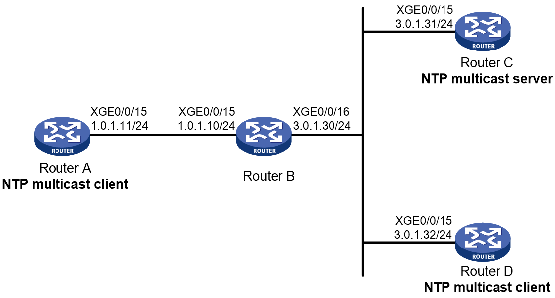
Procedure
1. Assign an IP address to each interface, and make sure the routers can reach each other, as shown in Figure 15. (Details not shown.)
2. Configure Router C:
# Enable the NTP service.
<RouterC> system-view
[RouterC] ntp-service enable
# Specify NTP for obtaining the time.
[RouterC] clock protocol ntp
# Specify the local clock as the reference source, with stratum level 2.
[RouterC] ntp-service refclock-master 2
# Configure Router C to operate in multicast server mode and send multicast messages from Ten-GigabitEthernet 0/0/15.
[RouterC] interface ten-gigabitethernet 0/0/15
[RouterC-Ten-GigabitEthernet0/0/15] ntp-service multicast-server
[RouterC-Ten-GigabitEthernet0/0/15] quit
3. Configure Router D:
# Enable the NTP service.
<RouterD> system-view
[RouterD] ntp-service enable
# Specify NTP for obtaining the time.
[RouterD] clock protocol ntp
# Configure Router D to operate in multicast client mode and receive multicast messages on Ten-GigabitEthernet 0/0/15.
[RouterD] interface ten-gigabitethernet 0/0/15
[RouterD-Ten-GigabitEthernet0/0/15] ntp-service multicast-client
[RouterD-Ten-GigabitEthernet0/0/15] quit
4. Verify the configuration:
# Verify that Router D has synchronized its time with Router C, and the clock stratum level of Router D is 3.
Router D and Router C are on the same subnet, so Router D can receive multicast messages from Router C without being enabled with the multicast function.
[RouterD-Ten-GigabitEthernet0/0/15] display ntp-service status
Clock status: synchronized
Clock stratum: 3
System peer: 3.0.1.31
Local mode: bclient
Reference clock ID: 3.0.1.31
Leap indicator: 00
Clock jitter: 0.044281 s
Stability: 0.000 pps
Clock precision: 2^-18
Root delay: 0.00229 ms
Root dispersion: 4.12572 ms
Reference time: d0d289fe.ec43c720 Sat, Jan 8 2011 7:00:14.922
Sync state from NTP server to local clock: clock synced
# Verify that an IPv4 NTP association has been established between Router D and Router C.
[RouterD-Ten-GigabitEthernet0/0/15] display ntp-service sessions
source reference stra reach poll now offset delay disper
********************************************************************************
[1245]3.0.1.31 127.127.1.0 2 1 64 519 -0.0 0.0022 4.1257
Notes: 1 source(master),2 source(peer),3 selected,4 candidate,5 configured.
Total sessions: 1
5. Configure Router B:
Because Router A and Router C are on different subnets, you must enable the multicast functions on Router B before Router A can receive multicast messages from Router C.
# Enable the IP multicast function.
<RouterB> system-view
[RouterB] multicast routing
[RouterB-mrib] quit
[RouterB] interface ten-gigabitethernet 0/0/15
[RouterB-Ten-GigabitEthernet0/0/15] igmp enable
[RouterB-Ten-GigabitEthernet0/0/15] igmp static-group 224.0.1.1
[RouterB-Ten-GigabitEthernet0/0/15] quit
[RouterB] interface ten-gigabitethernet 0/0/16
[RouterB-Ten-GigabitEthernet0/0/16] pim dm
[RouterB-Ten-GigabitEthernet0/0/16] quit
6. Configure Router A:
# Enable the NTP service.
<RouterA> system-view
[RouterA] ntp-service enable
# Specify NTP for obtaining the time.
[RouterA] clock protocol ntp
# Configure Router A to operate in multicast client mode and receive multicast messages from Ten-GigabitEthernet 0/0/15.
[RouterA] interface ten-gigabitethernet 0/0/15
[RouterA-Ten-GigabitEthernet0/0/15] ntp-service multicast-client
[RouterA-Ten-GigabitEthernet0/0/15] quit
Verifying the configuration
# Verify that Router A has synchronized its time with Router C, and the clock stratum level of Router A is 3.
[RouterA-Ten-GigabitEthernet0/0/15] display ntp-service status
Clock status: synchronized
Clock stratum: 3
System peer: 3.0.1.31
Local mode: bclient
Reference clock ID: 3.0.1.31
Leap indicator: 00
Clock jitter: 0.165741 s
Stability: 0.000 pps
Clock precision: 2^-18
Root delay: 0.00534 ms
Root dispersion: 4.51282 ms
Reference time: d0c61289.10b1193f Wed, Dec 29 2010 20:03:21.065
Sync state from NTP server to local clock: clock synced
# Verify that an IPv4 NTP association has been established between Router A and Router C.
[RouterA-Ten-GigabitEthernet0/0/15] display ntp-service sessions
source reference stra reach poll now offset delay disper
********************************************************************************
[1234]3.0.1.31 127.127.1.0 2 247 64 381 -0.0 0.0053 4.5128
Notes: 1 source(master),2 source(peer),3 selected,4 candidate,5 configured.
Total sessions: 1
Example: Configuring IPv6 NTP multicast association mode
Network configuration
As shown in Figure 16, configure Router C as the NTP server for multiple devices on different network segments so that these devices synchronize the time with Router C.
· Configure Router C's local clock as its reference source, with stratum level 2.
· Configure Router C to operate in IPv6 multicast server mode and send IPv6 NTP multicast messages from Ten-GigabitEthernet 0/0/15.
· Configure Router D and Router A to operate in multicast client mode and receive IPv6 multicast messages on Ten-GigabitEthernet 0/0/15.

Procedure
1. Assign an IP address to each interface, and make sure the routers can reach each other, as shown in Figure 16. (Details not shown.)
2. Configure Router C:
# Enable the NTP service.
<RouterC> system-view
[RouterC] ntp-service enable
# Specify NTP for obtaining the time.
[RouterC] clock protocol ntp
# Specify the local clock as the reference source, with stratum level 2.
[RouterC] ntp-service refclock-master 2
# Configure Router C to operate in IPv6 multicast server mode and send multicast messages from Ten-GigabitEthernet 0/0/15.
[RouterC] interface ten-gigabitethernet 0/0/15
[RouterC-Ten-GigabitEthernet0/0/15] ntp-service ipv6 multicast-server ff24::1
[RouterC-Ten-GigabitEthernet0/0/15] quit
3. Configure Router D:
# Enable the NTP service.
<RouterD> system-view
[RouterD] ntp-service enable
# Specify NTP for obtaining the time.
[RouterD] clock protocol ntp
# Configure Router D to operate in IPv6 multicast client mode and receive multicast messages on Ten-GigabitEthernet 0/0/15.
[RouterD] interface ten-gigabitethernet 0/0/15
[RouterD-Ten-GigabitEthernet0/0/15] ntp-service ipv6 multicast-client ff24::1
[RouterD-Ten-GigabitEthernet0/0/15] quit
4. Verify the configuration:
# Verify that Router D has synchronized its time with Router C, and the clock stratum level of Router D is 3.
Router D and Router C are on the same subnet, so Router D can receive the IPv6 multicast messages from Router C without being enabled with the IPv6 multicast functions.
[RouterD-Ten-GigabitEthernet0/0/15] display ntp-service status
Clock status: synchronized
Clock stratum: 3
System peer: 3000::2
Local mode: bclient
Reference clock ID: 165.84.121.65
Leap indicator: 00
Clock jitter: 0.000977 s
Stability: 0.000 pps
Clock precision: 2^-18
Root delay: 0.00000 ms
Root dispersion: 8.00578 ms
Reference time: d0c60680.9754fb17 Wed, Dec 29 2010 19:12:00.591
Sync state from NTP server to local clock: clock synced
# Verify that an IPv6 NTP association has been established between Router D and Router C.
[RouterD-Ten-GigabitEthernet0/0/15] display ntp-service ipv6 sessions
Notes: 1 source(master), 2 source(peer), 3 selected, 4 candidate, 5 configured.
Source: [1234]3000::2
Reference: 127.127.1.0 Clock stratum: 2
Reachabilities: 111 Poll interval: 64
Last receive time: 23 Offset: -0.0
Roundtrip delay: 0.0 Dispersion: 0.0
Total sessions: 1
5. Configure Router B:
Because Router A and Router C are on different subnets, you must enable the multicast functions on Router B so that Router A can receive IPv6 multicast messages from Router C.
# Enable the IPv6 multicast function.
<RouterB> system-view
[RouterB] ipv6 multicast routing
[RouterB-mrib6] quit
[RouterB] interface ten-gigabitethernet 0/0/15
[RouterB-Ten-GigabitEthernet0/0/15] mld enable
[RouterB-Ten-GigabitEthernet0/0/15] mld static-group ff24::1
[RouterB-Ten-GigabitEthernet0/0/15] quit
[RouterB] interface ten-gigabitethernet 0/0/16
[RouterB-Ten-GigabitEthernet0/0/16] ipv6 pim dm
[RouterB-Ten-GigabitEthernet0/0/16] quit
6. Configure Router A:
# Enable the NTP service.
<RouterA> system-view
[RouterA] ntp-service enable
# Specify NTP for obtaining the time.
[RouterA] clock protocol ntp
# Configure Router A to operate in IPv6 multicast client mode and receive multicast messages from Ten-GigabitEthernet 0/0/15.
[RouterA] interface ten-gigabitethernet 0/0/15
[RouterA-Ten-GigabitEthernet0/0/15] ntp-service ipv6 multicast-client ff24::1
[RouterA-Ten-GigabitEthernet0/0/15] quit
Verifying the configuration
# Verify that Router A has synchronized to Router C, and the clock stratum level is 3 on Router A and 2 on Router C.
[RouterA-Ten-GigabitEthernet0/0/15] display ntp status
Clock status: synchronized
Clock stratum: 3
System peer: 3000::2
Local mode: bclient
Reference clock ID: 165.84.121.65
Leap indicator: 00
Clock jitter: 0.165741 s
Stability: 0.000 pps
Clock precision: 2^-18
Root delay: 0.00534 ms
Root dispersion: 4.51282 ms
Reference time: d0c61289.10b1193f Wed, Dec 29 2010 20:03:21.065
# Verify that an IPv6 NTP association has been established between Router A and Router C.
[RouterA-Ten-GigabitEthernet0/0/15] display ntp-service ipv6 sessions
Notes: 1 source(master), 2 source(peer), 3 selected, 4 candidate, 5 configured.
Source: [124]3000::2
Reference: 127.127.1.0 Clock stratum: 2
Reachabilities: 2 Poll interval: 64
Last receive time: 71 Offset: -0.0
Roundtrip delay: 0.0 Dispersion: 0.0
Total sessions: 1
Example: Configuring NTP authentication in broadcast mode
Network configuration
As shown in Figure 17, configure Router C as the NTP server for multiple devices on the same segment so that these devices synchronize the time with Router C. Configure Router A and Router B to authenticate the NTP server.
· Configure Router C's local clock as its reference source, with stratum level 3.
· Configure Router C to operate in broadcast server mode and send broadcast messages from Ten-GigabitEthernet 0/0/15.
· Configure Router A and Router B to operate in broadcast client mode and receive broadcast messages on Ten-GigabitEthernet 0/0/15.
· Configure NTP authentication on Router A, Router B, and Router C.

Procedure
1. Assign an IP address to each interface, and make sure Router A, Router B, and Router C can reach each other, as shown in Figure 17. (Details not shown.)
2. Configure Router A:
# Enable the NTP service.
<RouterA> system-view
[RouterA] ntp-service enable
# Specify NTP for obtaining the time.
[RouterA] clock protocol ntp
# Enable NTP authentication on Router A. Create a plaintext NTP authentication key, with key ID of 88 and key value of 123456. Specify it as a trusted key.
[RouterA] ntp-service authentication enable
[RouterA] ntp-service authentication-keyid 88 authentication-mode md5 simple 123456
[RouterA] ntp-service reliable authentication-keyid 88
# Configure Router A to operate in broadcast client mode and receive NTP broadcast messages on Ten-GigabitEthernet 0/0/15.
[RouterA] interface ten-gigabitethernet 0/0/15
[RouterA-Ten-GigabitEthernet0/0/15] ntp-service broadcast-client
[RouterA-Ten-GigabitEthernet0/0/15] quit
3. Configure Router B:
# Enable the NTP service.
<RouterB> system-view
[RouterB] ntp-service enable
# Specify NTP for obtaining the time.
[RouterB] clock protocol ntp
# Enable NTP authentication on Router B. Create a plaintext NTP authentication key, with key ID of 88 and key value of 123456. Specify it as a trusted key.
[RouterB] ntp-service authentication enable
[RouterB] ntp-service authentication-keyid 88 authentication-mode md5 simple 123456
[RouterB] ntp-service reliable authentication-keyid 88
# Configure Router B to operate in broadcast client mode and receive NTP broadcast messages on Ten-GigabitEthernet 0/0/15.
[RouterB] interface ten-gigabitethernet 0/0/15
[RouterB-Ten-GigabitEthernet0/0/15] ntp-service broadcast-client
[RouterB-Ten-GigabitEthernet0/0/15] quit
4. Configure Router C:
# Enable the NTP service.
<RouterC> system-view
[RouterC] ntp-service enable
# Specify NTP for obtaining the time.
[RouterC] clock protocol ntp
# Specify the local clock as the reference source, with stratum level 3.
[RouterC] ntp-service refclock-master 3
# Configure Router C to operate in the NTP broadcast server mode and use Ten-GigabitEthernet 0/0/15 to send NTP broadcast messages.
[RouterC] interface ten-gigabitethernet 0/0/15
[RouterC-Ten-GigabitEthernet0/0/15] ntp-service broadcast-server
[RouterC-Ten-GigabitEthernet0/0/15] quit
5. Verify the configuration:
NTP authentication is enabled on Router A and Router B, but not enabled on Router C. Router A and Router B cannot synchronize their local clocks with Router C.
[RouterB-Ten-GigabitEthernet0/0/15] display ntp-service status
Clock status: unsynchronized
Clock stratum: 16
Reference clock ID: none
# Enable NTP authentication on Router C. Create a plaintext NTP authentication key, with key ID of 88 and key value of 123456. Specify it as a trusted key.
[RouterC] ntp-service authentication enable
[RouterC] ntp-service authentication-keyid 88 authentication-mode md5 simple 123456
[RouterC] ntp-service reliable authentication-keyid 88
# Specify Router C as an NTP broadcast server, and associate key 88 with Router C.
[RouterC] interface ten-gigabitethernet 0/0/15
[RouterC-Ten-GigabitEthernet0/0/15] ntp-service broadcast-server authentication-keyid 88
Verifying the configuration
# Verify that Router B has synchronized its time with Router C, and the clock stratum level of Router B is 4.
[RouterB-Ten-GigabitEthernet0/0/15] display ntp-service status
Clock status: synchronized
Clock stratum: 4
System peer: 3.0.1.31
Local mode: bclient
Reference clock ID: 3.0.1.31
Leap indicator: 00
Clock jitter: 0.006683 s
Stability: 0.000 pps
Clock precision: 2^-18
Root delay: 0.00127 ms
Root dispersion: 2.89877 ms
Reference time: d0d287a7.3119666f Sat, Jan 8 2011 6:50:15.191
Sync state from NTP server to local clock: clock synced
# Verify that an IPv4 NTP association has been established between Router B and Router C.
[RouterB-Ten-GigabitEthernet0/0/15] display ntp-service sessions
source reference stra reach poll now offset delay disper
********************************************************************************
[1245]3.0.1.31 127.127.1.0 3 3 64 68 -0.0 0.0000 0.0
Notes: 1 source(master),2 source(peer),3 selected,4 candidate,5 configured.
Configuring SNTP
About SNTP
SNTP is a simplified, client-only version of NTP specified in RFC 4330. It uses the same packet format and packet exchange procedure as NTP, but provides faster synchronization at the price of time accuracy.
Relationship between SNTP and NTP
The relationship between SNTP and NTP is as follows:
1. Purpose—Both SNTP and NTP aim to synchronize the time of computer systems.
2. Protocol family—SNTP is a subset of NTP and uses the same protocol family as NTP. SNTP uses the NTP message format.
3. Simplified version—NTP provides additional features to enhance time synchronization accuracy, such as complex error detection and correction algorithms, dynamic server selection, load balancing, and control protocols. SNTP typically does not provide these complex features.
4. Precision—NTP is designed to provide high-precision time synchronization on the network, typically at the millisecond level and even capable of reaching sub-millisecond levels. SNTP is suitable for scenarios where precision requirements are lower.
5. Compatibility—In most cases, SNTP and NTP are compatible, because they use the same PDU format. This design allows interoperability between SNTP clients and NTP servers, and between NTP clients and SNTP servers.
6. Application scenarios—SNTP, being a simplified version of NTP, is ideal for resource-constrained devices such as home routers and IP cameras, as well as applications where strict time accuracy is not critical. On the other hand, NTP is designed for use in scenarios demanding highly precise time synchronization, such as financial transaction systems, scientific research, and advanced network infrastructure.
SNTP operating mechanism
SNTP performs basic time synchronization by using some fields in NTP messages. It uses the same message exchange process as NTP but processes the received time information in a more simplified way, reducing complexity and resource requirements. The following is a typical SNTP time synchronization message exchange process:
1. The SNTP client generates an NTP message, sets the mode to client (mode 3), pads the original timestamp, and then sends it to the server.
2. Upon receiving the message, the NTP/SNTP server adds or updates the receive timestamp and transmit timestamp, sets the message mode to server (mode 4), and sends it back to the client as a response.
3. After receiving the response, the SNTP client logs the time when the response was received, extracts the transmission timestamp from the response, and adjusts the clock as needed.
Figure 18 SNTP operating mechanism
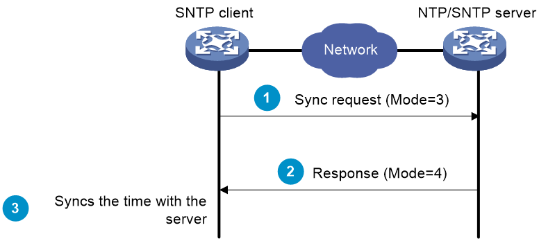
SNTP working mode
SNTP supports only the client/server mode. An SNTP-enabled device can receive time from NTP servers, but cannot provide time services to other devices.
If you specify multiple NTP servers for an SNTP client, the server with the best stratum is selected. If multiple servers are at the same stratum, the NTP server whose time packet is first received is selected.
Protocols and standards
RFC 4330, Simple Network Time Protocol (SNTP) Version 4 for IPv4, IPv6 and OSI
Restrictions and guidelines: SNTP configuration
When you configure SNTP, follow these restrictions and guidelines:
· You cannot configure both NTP and SNTP on the same device.
· You must use the clock protocol command to specify NTP for obtaining the time. For more information about the clock protocol command, see device management commands in Fundamentals Configuration Guide.
SNTP tasks at a glance
Tasks on the client
2. Specifying an NTP server for the device
3. (Optional.) Configuring SNTP authentication
4. (Optional.) Specifying the NTP time-offset thresholds for log and trap outputs
Tasks on the server
2. (Optional.) Configuring SNTP authentication
Enabling the SNTP service
Restrictions and guidelines
The NTP service and SNTP service are mutually exclusive. Before you enable SNTP, make sure NTP is disabled.
Procedure
1. Enter system view.
system-view
2. Enable the SNTP service.
sntp enable
By default, the SNTP service is disabled.
Specifying an NTP server for the device
Restrictions and guidelines
To use an NTP server as the time source, make sure its clock has been synchronized. If the stratum level of the NTP server is greater than or equal to that of the client, the client does not synchronize with the NTP server.
Procedure
1. Enter system view.
system-view
2. Specify an NTP server for the device.
IPv4:
sntp unicast-server { server-name | ip-address } [ vpn-instance vpn-instance-name ] [ authentication-keyid keyid | source interface-type interface-number | version number ] *
IPv6:
sntp ipv6 unicast-server { server-name | ipv6-address } [ vpn-instance vpn-instance-name ] [ authentication-keyid keyid | source interface-type interface-number ] *
By default, no NTP server is specified for the device.
You can specify multiple NTP servers for the client by repeating this step.
To perform authentication, you need to specify the authentication-keyid keyid option.
Configuring SNTP authentication
About this task
SNTP authentication ensures that an SNTP client is synchronized only to an authenticated trustworthy NTP server.
Restrictions and guidelines
Enable authentication on both the NTP server and the SNTP client.
Use the same authentication key ID, algorithm, and key on the NTP server and SNTP client. Specify the key as a trusted key on both the NTP server and the SNTP client. For information about configuring NTP authentication on an NTP server, see "Configuring NTP."
On the SNTP client, associate the specified key with the NTP server. Make sure the server is allowed to use the key ID for authentication on the client.
With authentication disabled, the SNTP client can synchronize with the NTP server regardless of whether the NTP server is enabled with authentication.
Configuring SNTP authentication on the client
1. Enter system view.
system-view
2. Enable SNTP authentication.
sntp authentication enable
By default, SNTP authentication is disabled.
3. Configure an SNTP authentication key.
sntp authentication-keyid keyid authentication-mode { hmac-sha-1 | hmac-sha-256 | hmac-sha-384 | hmac-sha-512 | md5 } { cipher | simple } string [ acl ipv4-acl-number | ipv6 acl ipv6-acl-number ] *
By default, no SNTP authentication key exists.
4. Specify the key as a trusted key.
sntp reliable authentication-keyid keyid
By default, no trusted key is specified.
5. Associate the SNTP authentication key with an NTP server.
IPv4:
sntp unicast-server { server-name | ip-address } [ vpn-instance vpn-instance-name ] authentication-keyid keyid
IPv6:
sntp ipv6 unicast-server { server-name | ipv6-address } [ vpn-instance vpn-instance-name ] authentication-keyid keyid
By default, no NTP server is specified.
Configuring SNTP authentication on the server
1. Enter system view.
system-view
2. Enable SNTP authentication.
sntp authentication enable
By default, SNTP authentication is disabled.
3. Configure an SNTP authentication key.
sntp authentication-keyid keyid authentication-mode { hmac-sha-1 | hmac-sha-256 | hmac-sha-384 | hmac-sha-512 | md5 } { cipher | simple } string [ acl ipv4-acl-number | ipv6 acl ipv6-acl-number ] *
By default, no SNTP authentication key exists.
4. Specify the key as a trusted key.
sntp reliable authentication-keyid keyid
By default, no trusted key is specified.
Specifying the SNTP time-offset thresholds for log and trap outputs
About this task
By default, the SNTP client synchronizes the time with the server and outputs a log and a trap when the time offset between the client and server exceeds 128 ms for multiple times.
After you set the SNTP time-offset thresholds for log and trap outputs, the SNTP client synchronizes the time with the server when the time offset exceeds 128 ms for multiple times, but outputs a log or trap only when the time offset exceeds the specified threshold.
Procedure
1. Enter system view.
system-view
2. Specify the SNTP time-offset thresholds for log and trap outputs.
sntp time-offset-threshold { log log-threshold | trap trap-threshold } *
By default, no SNTP time-offset thresholds are set for log and trap outputs.
Display and maintenance commands for SNTP
Execute display commands in any view.
|
Task |
Command |
|
Display information about all IPv6 SNTP associations. |
display sntp ipv6 sessions |
|
Display information about all IPv4 SNTP associations. |
display sntp sessions |
SNTP configuration examples
Example: Configuring SNTP
Network configuration
As shown in Figure 19, perform the following tasks:
· Configure Device A's local clock as its reference source, with stratum level 2.
· Configure Device B to operate in SNTP client mode, and specify Device A as the NTP server.
· Configure NTP authentication on Device A and SNTP authentication on Device B.

Procedure
1. Assign an IP address to each interface, and make sure Device A and Device B can reach each other, as shown in Figure 19. (Details not shown.)
2. Configure Device A:
# Enable the NTP service.
<DeviceA> system-view
[DeviceA] ntp-service enable
# Specify NTP for obtaining the time.
[DeviceA] clock protocol ntp
# Configure the local clock as the reference source, with stratum level 2.
[DeviceA] ntp-service refclock-master 2
# Enable NTP authentication on Device A.
[DeviceA] ntp-service authentication enable
# Configure a plaintext NTP authentication key, with key ID of 10 and key value of aNiceKey.
[DeviceA] ntp-service authentication-keyid 10 authentication-mode md5 simple aNiceKey
# Specify the key as a trusted key.
[DeviceA] ntp-service reliable authentication-keyid 10
3. Configure Device B:
# Enable the SNTP service.
<DeviceB> system-view
[DeviceB] sntp enable
# Specify NTP for obtaining the time.
[DeviceB] clock protocol ntp
# Enable SNTP authentication on Device B.
[DeviceB] sntp authentication enable
# Configure a plaintext authentication key, with key ID of 10 and key value of aNiceKey.
[DeviceB] sntp authentication-keyid 10 authentication-mode md5 simple aNiceKey
# Specify the key as a trusted key.
[DeviceB] sntp reliable authentication-keyid 10
# Specify Device A as the NTP server of Device B, and associate the server with key 10.
[DeviceB] sntp unicast-server 1.0.1.11 authentication-keyid 10
Verifying the configuration
# Verify that an SNTP association has been established between Device B and Device A, and Device B has synchronized its time with Device A.
[DeviceB] display sntp sessions
NTP server Stratum Version Last receive time
1.0.1.11 2 4 Tue, May 17 2011 9:11:20.833 (Synced)
