- Table of Contents
-
- H3C Wi-Fi7 Indoor Access Points Installation Guide-5W106
- 00-Preface
- 01-Installing the device
- 02-Logging in to the device
- 03-Appendix A AP views and technical specifications
- 04-Appendix B LEDs and buttons
- 05-Appendix C Optional transceiver modules
- 06-Appendix D Connecting the hybrid copper-fiber cable
- 07-Appendix E Cabling recommendations
- 08-Appendix F RED Declaration of Conformity
- Related Documents
-
| Title | Size | Download |
|---|---|---|
| 01-Installing the device | 1.71 MB |
General safety recommendations
Determining the installation position
Introduction to cable connections
Connecting a common optical fiber
Connecting a hybrid copper-fiber cable
5 (Optional.) Installing the cable management plate
7 Connecting the AP to the network
Verifying that the AP has been connected to the network when it operates in fit mode
Verifying that the AP has been connected to the network when it operates in cloud mode
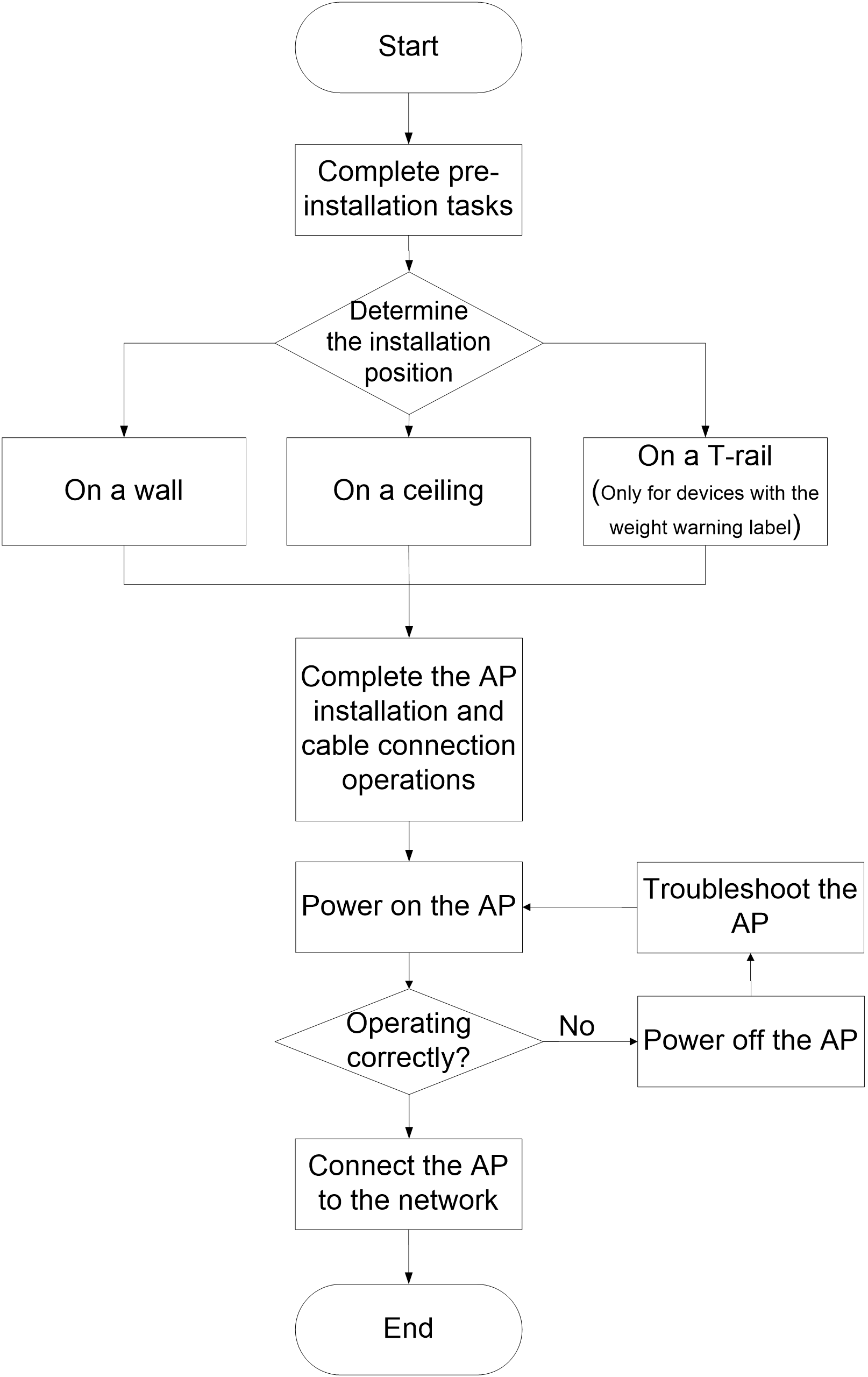
1 Installation flowchart
The H3C Wi-Fi7 indoor wireless APs include the following models:
· WA7220-HI
· WA7320i
· WA7338-HI
· WA7539
· WA7638
Before powering on the device, make sure you have completed all installation steps.
Figure1-1 Installation flowchart
2 Preparing for installation
Safety recommendations
Safety labels
|
|
IMPORTANT: · The AP can only be gained by SERVICE PERSONS or by USERS who have been instructed about the reasons for the restrictions applied to the location and about any precautions that shall be taken. · The AP is secured by using a tool, lock and key, or other security means, which may vary by actual deployment scenario, and is controlled by the authorized responsible for the location. |
|
Safety label |
Description |
|
|
Hot surface warning label. A device attached with this label might have a hot surface during operation. Install the device in a restricted access location. Only servicing engineers or trained personnel can operate the devices in the access location. · Hot parts: Text that identifies the nature of the class 2 or class 3 energy source or the consequences that can be caused by the energy source, and the location of the energy source. · Burned fingers when handling the parts: Text that describes the possible consequences of energy transfer from the energy source to a body part. · Wait one-half hour after switching off before handling parts: Text that describes the safeguard action necessary to avoid energy transfer to a body part. |
|
|
Device weight warning label. If the device is attached with this label, use the wall mounting or T-rail mounting method as a best practice. The figure is for illustration only. |


General safety recommendations
|
|
WARNING! Only professional technical personnel can install and remove the AP and its accessories. You must read all safety instructions carefully before working with the AP. |
To avoid possible bodily injury and equipment damage, read the following safety recommendations before installing the AP. Note that the recommendations do not cover every possible hazardous condition.
· To avoid bodily injury and device damage, take adequate safety measures.
· Place the AP in a dry and flat location and take anti-slip measures.
· Keep the AP clean and dust-free.
· Do not place the AP in a moist area and avoid liquid intrusion.
· Keep the AP and installation tools away from walkways.
Site preparation
Before installation, check the installation conditions of the device, including temperature, humidity, and operating altitude, to ensure that the device remains in a good operating environment in the long term. For more information about the temperature, humidity, and operating altitude requirements for the device, see "Appendix A AP views and technical specifications."
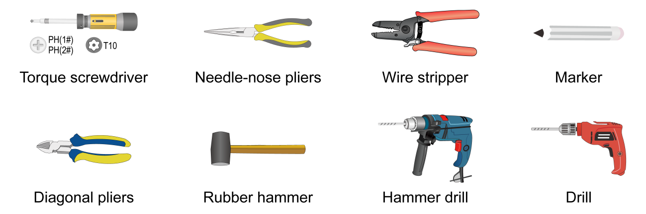
Installation tools
When installing the AP, you might need the following tools. Prepare the installation tools yourself as required.
Figure2-1 Installation tools
Pre-installation tasks
Before installing the AP, perform the following tasks:
· Connect the AP to a power source and the network. Examine the LEDs to verify that the AP is operating correctly. For information about AP LEDs, see "Appendix B LEDs and buttons".
· Record the MAC address and serial number at the rear of the AP for future use.
· Make sure you have completed cabling at the installation site.
· If the Ethernet interface rate is 1, 2.5, or 5 Gbps, use Cat-5e or above network cables. If the Ethernet interface rate is 10 Gbps, use Cat-6a or above network cables. For information about the supported interface rates, see "Appendix A AP views and technical specifications".
· The AP is typically installed on a high position. As a best practice, access and configure the AP before installing it.
· If a cable is routed outdoors, make sure a lighting arrester is attached to the AP port. Prepare a lighting arrester yourself as needed.
Determining the installation position
Determine the installation position by observing the following principles:
· Few obstacles such as wall exist between the AP and clients.
· The AP is far away from electronic devices (such as microwave oven) that might generate radio frequency (RF) noise.
· The AP does not hinder people’s daily work and life.
· The place is not water seeping, water soaking, and condensing.
3 Installing the AP
|
|
IMPORTANT: · Before powering on the device, make sure you have completed all installation steps. · For models with a weight-warning label, use wall mounting or T-rail mounting as a best practice. · Install an M3 × 23.5 security screw as required. · Since the installation steps are the same, the following illustrations are only provided as an example for one model. For illustrations of other models, see the corresponding quick installation guide. |
Installation accessories
Table3-1 Installation accessories
|
Installation accessories |
Applicable AP models |
|
|
Mounting bracket (provided)
|
M3 × 23.5 security screw (provided)
|
· WA7220-HI · WA7320i · WA7338-HI · WA7539 · WA7638 |
|
Screw and screw anchor (provided)
|
M4 × 30 pan-head screw (provided)
|
|
|
T-rail kit
|
Provided: · WA7338-HI · WA7538 · WA7638 Optional: · WA7220-HI · WA7320i |
|
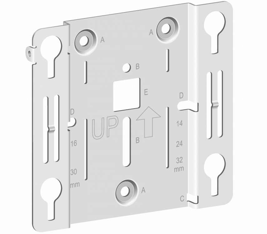
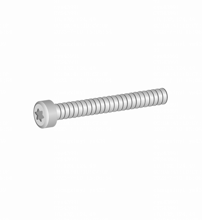
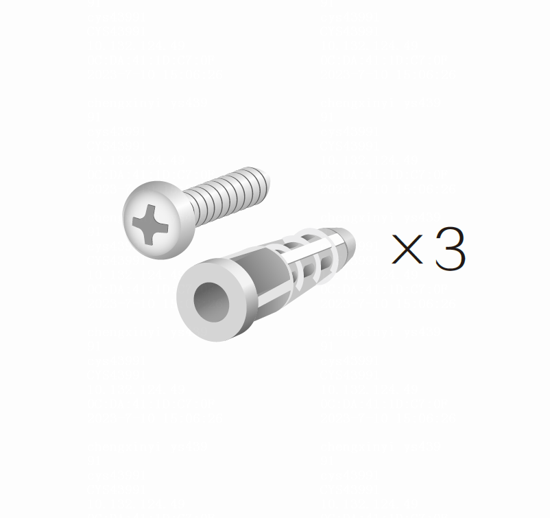
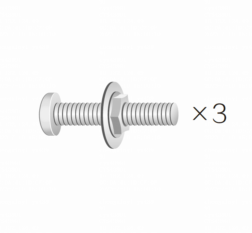
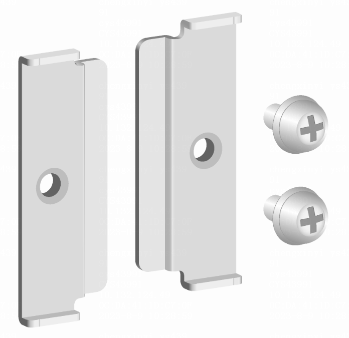
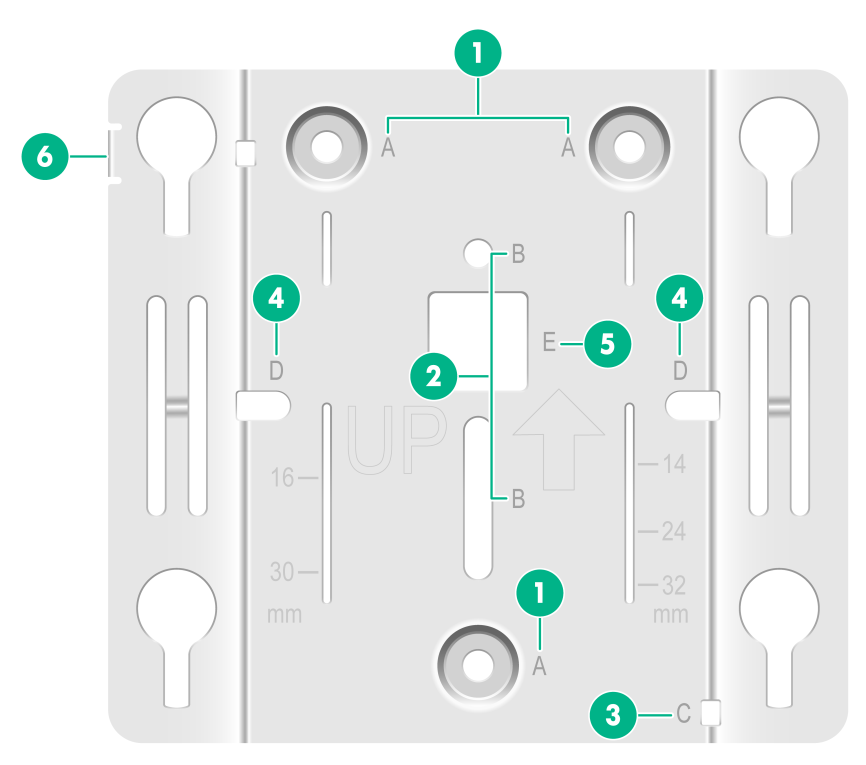
Figure3-1 Mounting bracket
|
(1) (A holes) Wall/ceiling mounting holes, used for securing the mounting bracket to the wall/ceiling |
|
(2) (B holes) T-rail mounting holes, used for securing the mounting bracket to a T-rail |
|
(3) (C hole) Auxiliary cable management hole. Thread a cable tie through the hole to secure cables. |
|
(4) (D holes) 86 panel mounting holes, used for securing the mounting bracket to an 86 panel. The distance between the two holes is 60 mm (2.36 in). |
|
(5) (E hole) Thread a cable through the hole to connect the AP |
|
(6) Security hole, applicable to the M3 × 23.5 security screw |
Mounting the AP on a wall
1. Place the mounting bracket against the wall and mark the installation holes on the wall.
Figure3-2 Marking the installation holes on the wall (using the WA7539 as an example)

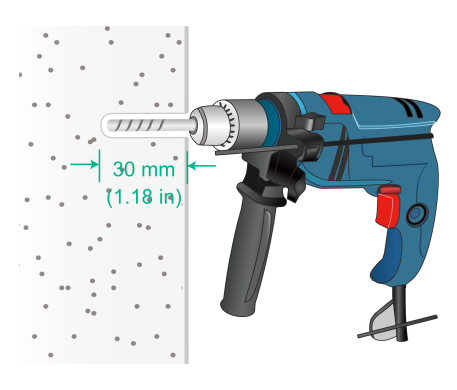
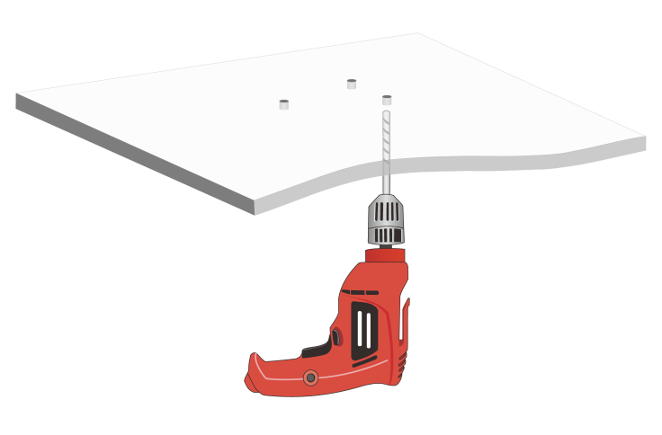
2. Drill three holes with a diameter of 6 mm (0.24 in) and a depth of 30 mm (1.18 in) at the marked locations, as shown in Figure3-3.
Figure3-3 Drilling holes in the wall (using the WA7539 as an example)
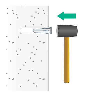
3. Insert a screw anchor into each hole, and tap the screw anchor with a rubber hammer until it is all flush with the wall surface, as shown in Figure3-4.
Figure3-4 Hammering the screw anchor into the wall (using the WA7539 as an example)
4. Thread the M3 × 23.5 security screw through the security hole in the mounting bracket. Make sure the screw does not block the keyhole slot.
Figure3-5 Inserting the security screw (using the WA7539 as an example)

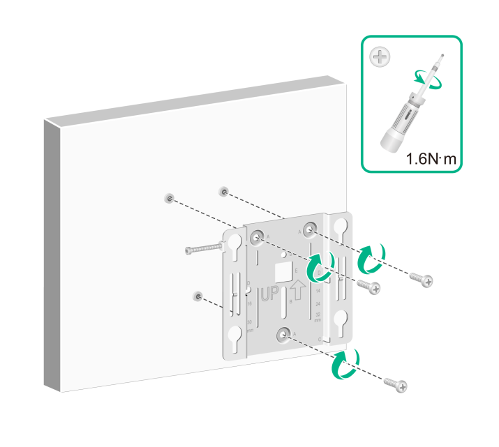
5. Insert the screws through the installation holes in the mounting bracket into the holes in the wall. Fasten the screws to secure the mounting bracket to the wall, as shown in Figure3-6.
Figure3-6 Attaching the mounting bracket to the wall (using the WA7539 as an example)
6. Connect the cable to the AP, see "Connecting cables."
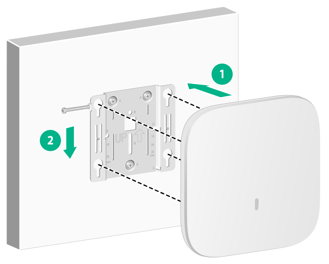
7. Position the four pegs at the AP rear into the keyhole slots in the mounting bracket and then slide the AP down until it sits securely in the keyhole slots, as shown in Figure3-7.
Figure3-7 Attaching the AP to the mounting bracket (using the WA7539 as an example)
8. Use a security Torx screwdriver to fasten the M3 × 23.5 security screw.
Figure3-8 Fastening the M3 × 23.5 security screw (using the WA7539 as an example)

Mounting the AP on a ceiling
|
|
CAUTION: The ceiling for installing the AP must be less than 18 mm (0.71 in) in thickness, and can bear a load of 5 kg (11.02 lb). If you must install the AP on a ceiling not strong enough, use boards to reinforce the ceiling. |
The installation method for the M3 × 23.5 security screw is similar when the AP is mounted on the wall and on the ceiling.
To mount the AP on a ceiling:
1. Remove the ceiling tile.
2. Place the mounting bracket against the ceiling tile and mark the installation holes on the ceiling tile. Drill three holes with a diameter of 6 mm (0.24 in) at the marked positions, as shown in Figure3-9.
Figure3-9 Drilling holes in the ceiling tile (using the WA7539 as an example)
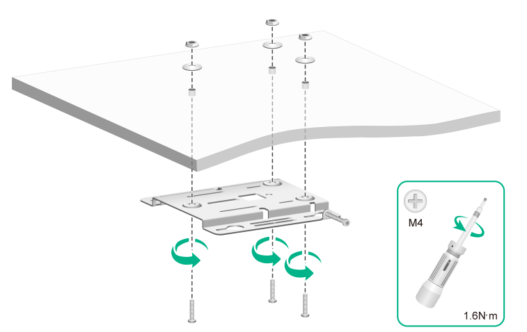
3. Thread the pan-head screws through the installation holes in the mounting bracket and into the holes in the ceiling tile. Fasten washers and nuts at the other side of the ceiling to secure the mounting bracket to the ceiling, as shown in Figure3-10.
Figure3-10 Attaching the mounting bracket to the ceiling (using the WA7539 as an example)
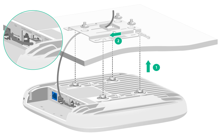
4. Connect the cable to the AP, see "Connecting cables."
5. Then position the four pegs at the AP rear into the keyhole slots in the mounting bracket and slide the AP until it sits securely in the keyhole slots.
Figure3-11 Attaching the AP to the mounting bracket (using the WA7539 as an example)
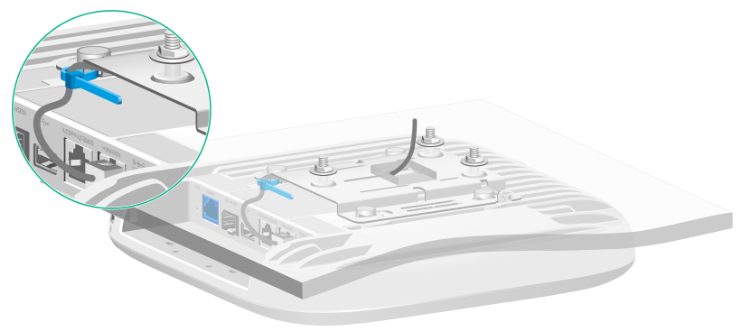
(Optional.) You can use a cable tie to secure the cable before attaching the AP to the mounting bracket. First thread the cable tie through the auxiliary hole in the mounting bracket, leaving the cable tie unfastened, and then adjust the cable length and fasten the cable tie to secure the cable.
No cable tie is provided with the AP. Prepare one yourself as required.
Figure3-12 Using a cable tie to secure the cable (using the WA7539 as an example)
6. Verify that the AP is installed securely to prevent it from falling off.
Mounting the AP on a T-rail
|
|
CAUTION: · Make sure the T-rail can bear a load of 5 kg (11.02 lb). · Make sure the T-rail has a thickness of not greater than 3.2 mm (0.13 in) and a width in the range of 17.5 to 34 mm (0.69 to 1.34 in). |
The installation method for the M3 × 23.5 security screw is similar when the AP is mounted on the wall and on a T-rail.
To mount the AP on a T-rail:
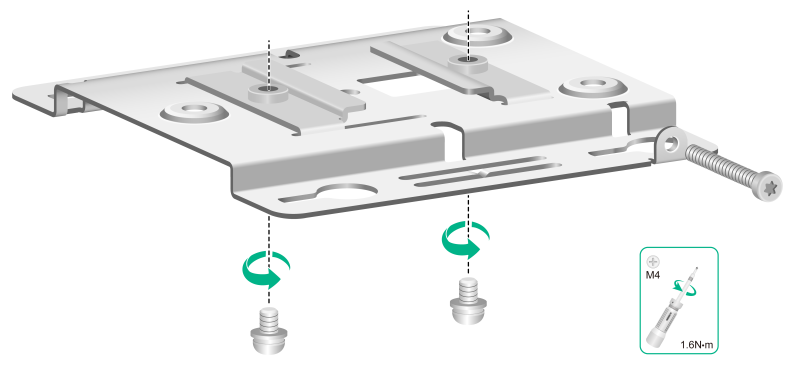
1. Use M4 T-rail clip screws to secure the T-rail clips to the mounting bracket. Do not fasten the left screw all the way in, leaving a certain space for adjusting the distance between the T-rail clips.
Figure3-13 Installing T-rail clips (using the WA7539 as an example)
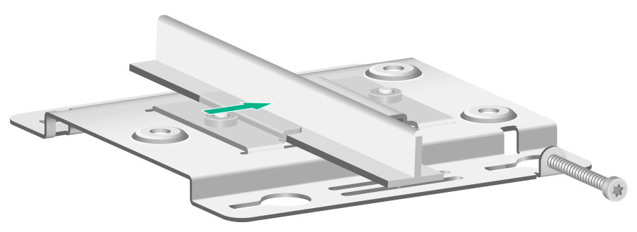
2. Adjust the distance between T-rail clips based on the width of the T-rail. Use a Phillips screwdriver to fasten the left M4 T-rail clip screw.
Figure3-14 Adjusting the distance between the T-rail clips (using the WA7539 as an example)
3. Connect the cable to the AP, see "Connecting cables."
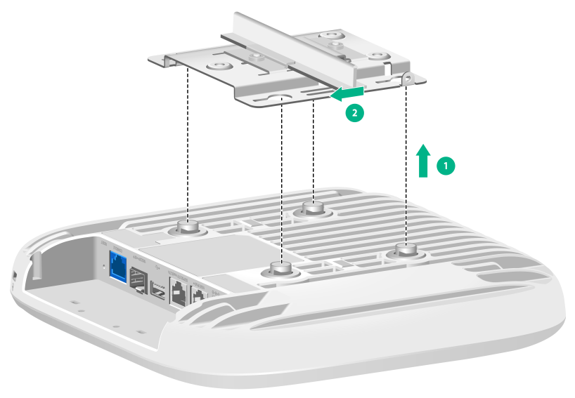
4. Position the four pegs at the AP rear into the keyhole slots in the mounting bracket and slide the AP until it sits securely in the keyhole slots.
Figure3-15 Install the AP (using the WA7539 as an example)
5. Verify that the AP is installed securely to prevent it from falling off.
4 Connecting cables
Introduction to cable connections
Cable connection explanation
Before you connect cables to the AP, make sure cable routing is completed on the installation site. For more information about cable routing, see "Appendix E Cabling recommendations." Table4-1 shows the cables available for the AP.
|
Port |
Cable |
Applicable AP models |
|
Power port |
Use a DC power adapter that has a round connector with a diameter of 5.5 or 2.1 mm (0.22 or 0.08 in) to supply power for the AP. See "Connecting a power adapter." |
· WA7220-HI · WA7320i · WA7338-HI · WA7539 · WA7638 |
|
Ethernet port |
Use an Ethernet cable to connect a switch to supply PoE power for the AP. See "Connecting an Ethernet cable." |
|
|
Fiber port |
Use a common optical fiber for network connection. See "Connecting a common optical fiber." |
|
|
Use a hybrid copper-fiber cable for power supply and network connection. See "Connecting a hybrid copper-fiber cable." |
The cable connection scheme varies by powering option. Select a cable connection scheme as required. For more information, see "Cable connection schemes."
Cable connection schemes
The AP supports different powering and communication options. Read chapters from "Connecting a power adapter" to "Connecting a hybrid copper-fiber cable" and see Table4-1 before you select a cable connection scheme as required.
The following figures are only for your reference.
Powering the AP by using a power adapter
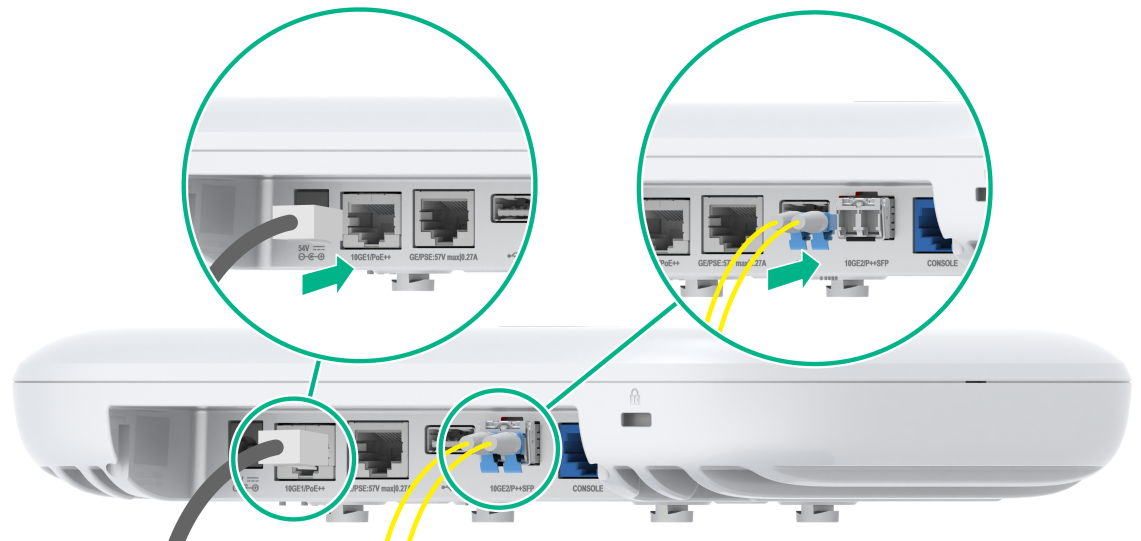
· Connect an uplink port on the AP to an Ethernet port for communication and power the AP by using a power adapter.
· Install a common transceiver module in an uplink port on the AP for communication and power the AP by using a power adapter.
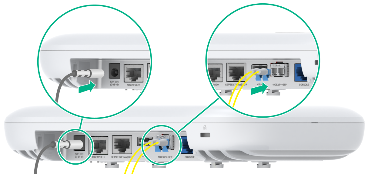
Figure4-1 Installing a transceiver module and powering the AP by using a power adapter (using the WA7539 as an example)
Power the AP through PoE
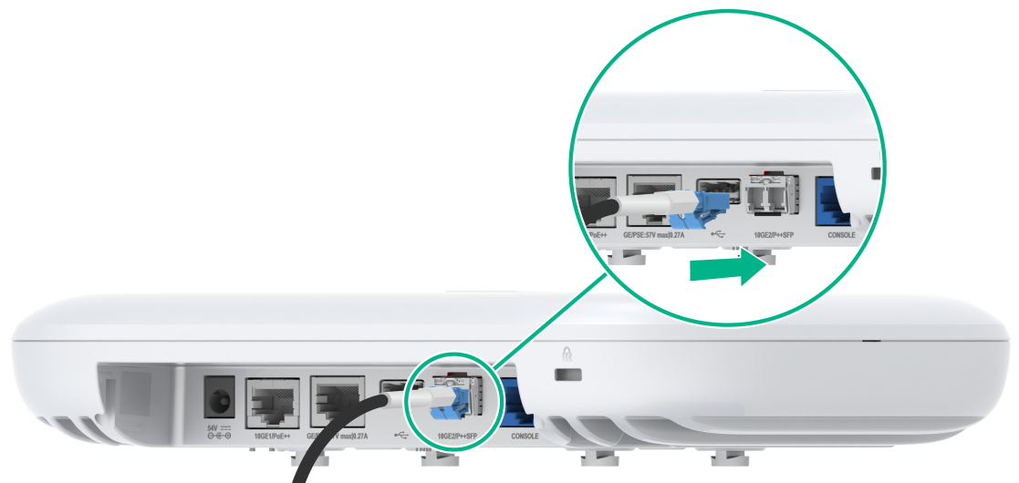
· Use an Ethernet cable to connect the PoE port on the AP and PoE switch for PoE power supply and communication.
· Install a common transceiver module in an uplink port on the AP for communication and use an Ethernet cable to connect the AP and PoE switch for PoE power supply.
Figure4-2 Installing a transceiver module and powering the AP through PoE (using the WA7539 as an example)
Powering the AP by using a PoE optical transceiver module
An uplink port on the AP uses a PoE optical transceiver module and a hybrid copper-fiber cable for receiving power and communication. You do not need to connect other cables.
Figure4-3 Powering the AP by using a PoE optical transceiver module (using the WA7539 as an example)
Connecting a power adapter
No power adapter is provided with the AP. Purchase a power adapter from H3C as required.
Table4-2 Power adapter specifications
|
Item |
Description |
Applicable AP models |
|
Input |
100 to 240 VAC |
All models |
|
Output |
48 to 55 VDC |
|
|
Output power |
≥ 40 W |
WA7320i |
|
≥ 60 W |
· WA7220-HI · WA7338-HI · WA7539 · WA7638 |
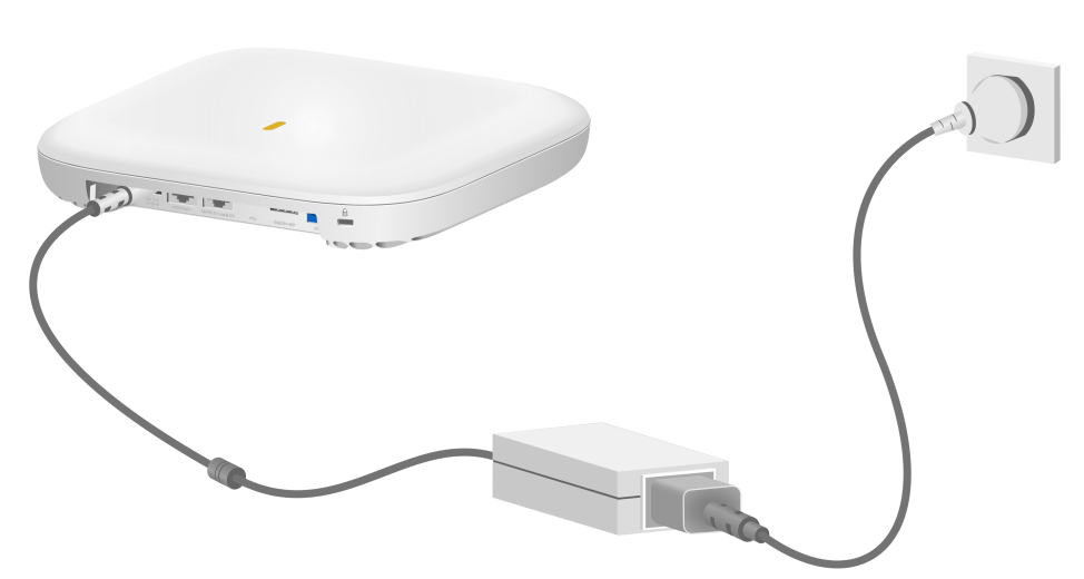
As shown in Figure4-4, you can use a power adapter to connect the AP to a local power source.
Figure4-4 Using a power adapter to connect the AP to a local power source (using the WA7539 as an example)
Connecting an Ethernet cable
|
|
NOTE: · The WA7338-HI, WA7539 and WA7638 require an 802.3bt-compliant PoE switch for supply power. This power supply method can provide a maximum output of 60 W. · The WA7220-HI and WA7320i require an 802.3at-compliant PoE switch for power supply. This power supply method can provide a maximum output of 30 W. |
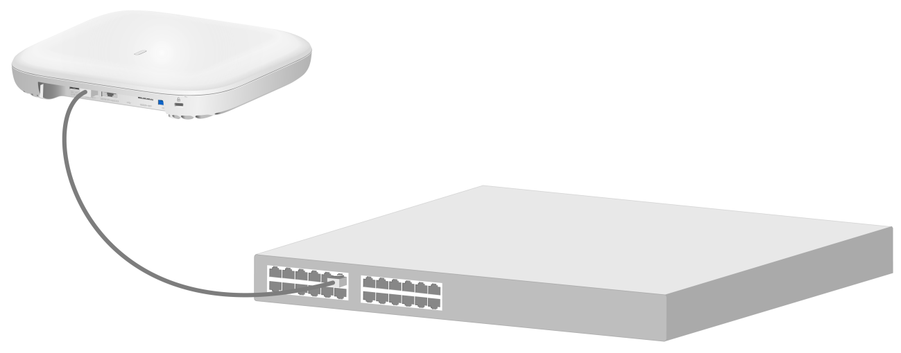
As shown in Figure4-5, use an Ethernet cable to connect the Ethernet port on the PoE switch to the PoE Ethernet port on the AP. The cable provides power supply connection and network access.
Figure4-5 Connecting an Ethernet cable (using the WA7539 as an example)
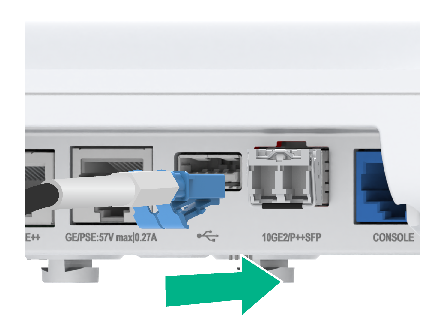
Connecting a common optical fiber
The fiber ports on the AP support only LC connectors. Purchase common transceiver modules yourself as required. For more information about common transceiver modules, see "Appendix C Optional transceiver modules."
To connect common optical fibers:
1. Holding both sides of the common transceiver module, insert the transceiver module slowly into the port.
2. Remove the dust caps from the optical fiber LC connectors.
3. Identify the Rx and Tx ports on the transceiver module. Use optical fibers with LC connectors to connect the Rx port and Tx port on the transceiver module to the Tx port and Rx port on the peer end, respectively.
Figure4-6 Connecting common optical fibers (using the WA7539 as an example)
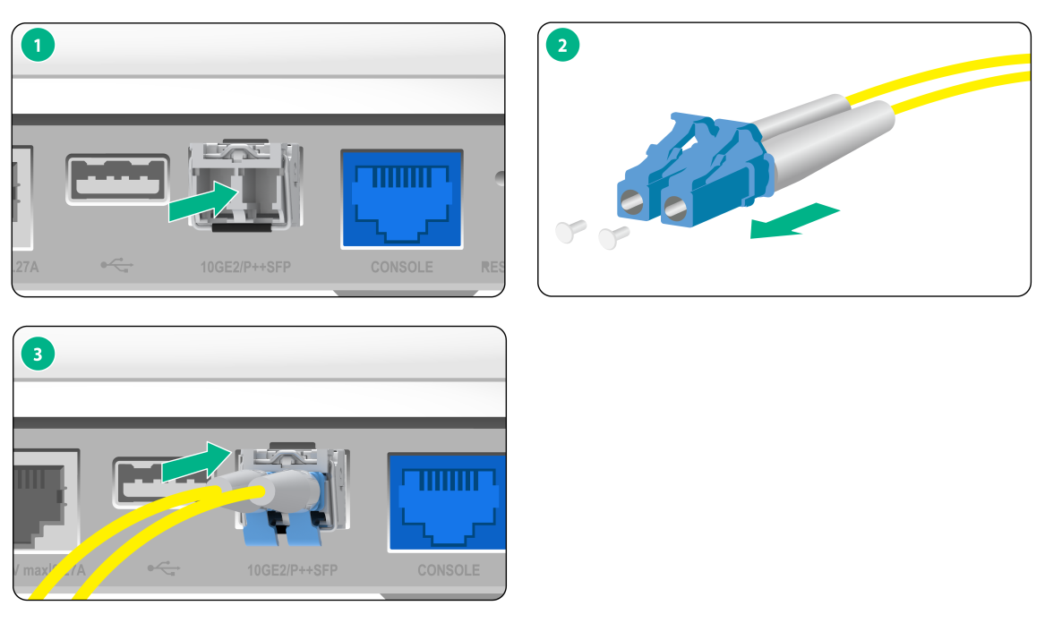
Connecting a hybrid copper-fiber cable
The AP supports PoE optical transceiver modules. Purchase them yourself as required. For more information about the PoE optical transceiver modules, see "Appendix C Optional transceiver modules."
To connect a hybrid copper-fiber cable:
1. Strip the hybrid copper-fiber cable, fusion splice optical fibers, and splice copper wires. For more information, see "Appendix D Connecting the hybrid copper-fiber cable."
2. Holding both sides of the PoE optical transceiver module, insert the transceiver module slowly into the port.
3. Connect one end of the hybrid copper-fiber cable to the PoE optical transceiver module.
Figure4-7 Connecting a hybrid copper-fiber cable (using the WA7539 as an example)
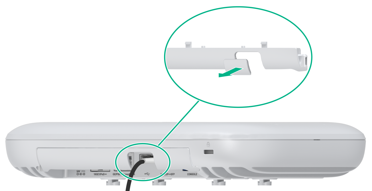
5 (Optional.) Installing the cable management plate
|
|
NOTE: This chapter is applicable only to the WA7220-HI、WA7338-HI, WA7539 and WA7638. |
After connecting all the cables, install the cable management plate. If an optical fiber is connected to the fiber port, you can remove the U-shaped plastic plate to facilitate cable routing as shown in Figure5-1.
Figure5-1 Removing the U-shaped plastic plate (using the WA7539 as an example)
6 Powering on the AP
Before powering on the AP, make sure you have completed all the installation steps.
Check before power-on
After you install the AP, perform the following tasks each time before you power on the AP:
· When you power the AP by using a power adapter, verify that the local AC power source is reliably grounded.
· When you power the AP through PoE, make sure the PoE power supply device is reliably grounded.
· When you power the AP by using a PoE optical transceiver module, make sure the iOptical host is reliably grounded.
Check after power-on
Examine the LEDs on the AP after you power on it to verify that the AP is operating correctly. For more information about the LEDs, see "Appendix B LEDs and buttons."
7 Connecting the AP to the network
Verifying that the AP has been connected to the network when it operates in fit mode
When the AP operates in fit mode, all AP settings are configured on the AC. To verify the network connectivity of the AP, execute the display wlan ap all command on the AC. If the AP status is R/M, the AP has been connected to the network.
<AC> display wlan ap all
Total number of APs: 1
Total number of connected APs: 1
Total number of connected manual APs: 1
Total number of connected auto APs: 0
Total number of connected common APs: 1
Total number of connected WTUs: 0
Total number of inside APs: 0
Maximum supported APs: 3072
Remaining APs: 3071
Total AP licenses: 128
Remaining AP licenses: 127
AP information
State : I = Idle, J = Join, JA = JoinAck, IL = ImageLoad
C = Config, DC = DataCheck, R = Run M = Master, B = Backup
AP name AP ID State Model Serial ID
ap1 1 R/M WA7539 219801A5JR8224E00031
Verifying that the AP has been connected to the network when it operates in cloud mode
When the AP operates in cloud mode, use a wireless terminal to search for and access the wireless service provided by the AP. If you can access external networks, the AP has been connected to the network.
