- Table of Contents
-
- 08-IP Multicast Configuration Guide
- 00-Preface
- 01-Multicast overview
- 02-IGMP snooping configuration
- 03-PIM snooping configuration
- 04-Multicast VLAN configuration
- 05-Multicast routing and forwarding configuration
- 06-IGMP configuration
- 07-PIM configuration
- 08-MSDP configuration
- 09-Multicast VPN configuration
- 10-MLD snooping configuration
- 11-IPv6 PIM snooping configuration
- 12-IPv6 multicast VLAN configuration
- 13-IPv6 multicast routing and forwarding configuration
- 14-MLD configuration
- 15-IPv6 PIM configuration
- Related Documents
-
| Title | Size | Download |
|---|---|---|
| 12-IPv6 multicast VLAN configuration | 136.12 KB |
Configuring IPv6 multicast VLANs
Sub-VLAN-based IPv6 multicast VLAN
Port-based IPv6 multicast VLAN
Restrictions and guidelines: IPv6 multicast VLAN configuration
Configuring a sub-VLAN-based IPv6 multicast VLAN
Setting the maximum number of IPv6 multicast VLAN forwarding entries
Display and maintenance commands for IPv6 multicast VLANs
IPv6 multicast VLAN configuration examples
Example: Configuring sub-VLAN-based IPv6 multicast VLAN
Configuring IPv6 multicast VLANs
IPv6 multicast VLAN function
As shown in Figure 1, Host A, Host B, and Host C are in different VLANs and the same IPv6 multicast group. When Device A (Layer 3 device) receives IPv6 multicast data for that group, it forwards three copies of the data to Device B (Layer 2 device). This occupies a large amount of bandwidth and increases the burden on the Layer 3 device.
Figure 1 Multicast transmission without the IPv6 multicast VLAN feature
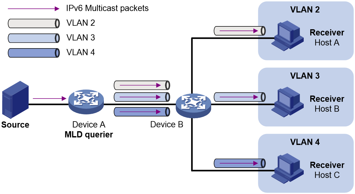
After an IPv6 multicast VLAN is configured on Device B, Device A sends one copy of the IPv6 multicast data to the IPv6 multicast VLAN on Device B. This saves network bandwidth and lessens the burden on the Layer 3 device.
IPv6 multicast VLAN methods
IPv6 multicast VLANs include sub-VLAN-based IPv6 multicast VLANs and port-based IPv6 multicast VLANs. Port-based IPv6 multicast VLANs are not supported in the current software version.
Sub-VLAN-based IPv6 multicast VLAN
As shown in Figure 2:
· Host A, Host B, and Host C are in VLAN 2 through VLAN 4, respectively.
· On Device B, VLAN 10 is an IPv6 multicast VLAN. VLAN 2 through VLAN 4 are sub-VLANs of VLAN 10.
· MLD snooping is enabled for the multicast VLAN and its sub-VLANs.
Figure 2 Sub-VLAN-based multicast VLAN
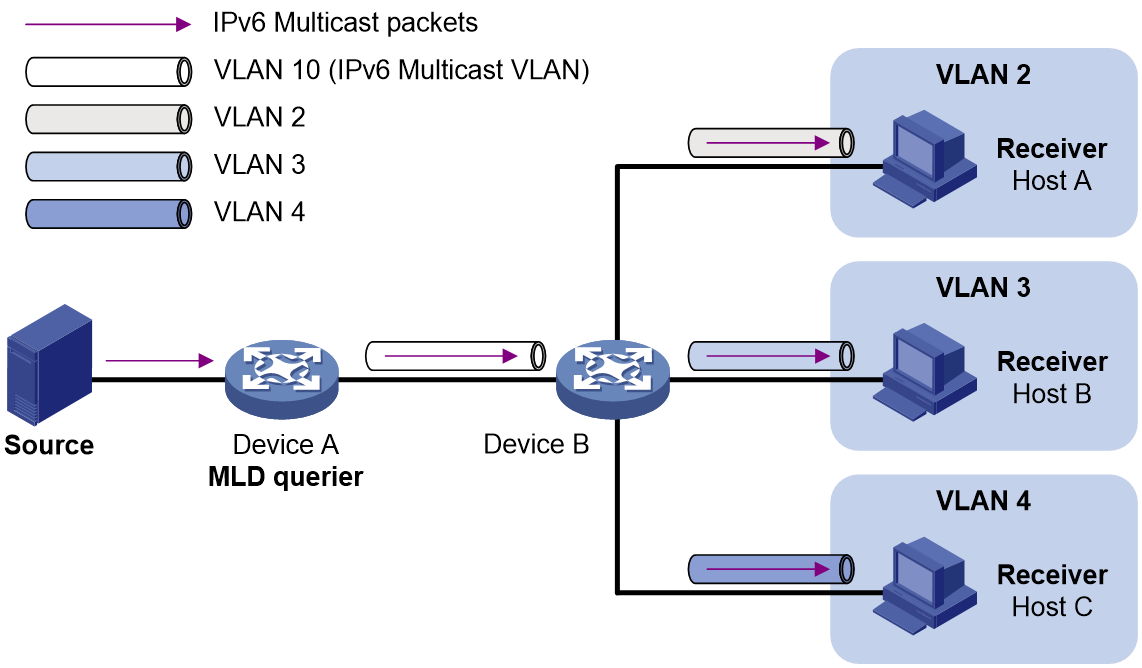
MLD snooping manages router ports in the IPv6 multicast VLAN and member ports in each sub-VLAN. When Device A receives IPv6 multicast data from the IPv6 multicast source, it sends only one copy of the IPv6 multicast data to the IPv6 multicast VLAN on Device B. Then, Device B sends a separate copy to each sub-VLAN of the IPv6 multicast VLAN.
Port-based IPv6 multicast VLAN
As shown in Figure 3:
· Host A, Host B, and Host C are in VLAN 2 through VLAN 4, respectively. All the user ports (ports with attached hosts) on Device B are hybrid ports.
· On Device B, VLAN 10 is an IPv6 multicast VLAN. All the user ports are assigned to VLAN 10.
· MLD snooping is enabled for the IPv6 multicast VLAN and its sub-VLANs.
Figure 3 Port-based IPv6 multicast VLAN
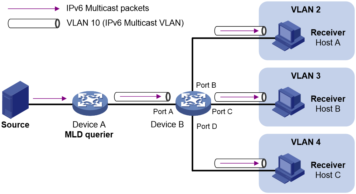
MLD snooping manages the router ports and member ports in the IPv6 multicast VLAN. When Device A receives IPv6 multicast data from the IPv6 multicast source, it sends only one copy of the IPv6 multicast data to the IPv6 multicast VLAN on Device B. Then, Device B sends a separate copy to each user port in the IPv6 multicast VLAN.
Restrictions and guidelines: IPv6 multicast VLAN configuration
This feature is available only for the following cards:
|
Card category |
Cards |
|
CEPC |
NP5 cards-CEPC |
|
CSPC |
FPGA cards-CSPC |
|
CSPEX |
NP5 cards-CSPEX, FPGA cards-CSPEX |
|
SPEX |
FPGA cards-SPEX |
|
SPE |
NP5 cards-SPE |
The VLAN to be configured as an IPv6 multicast VLAN must exist, only one IPv6 multicast VLAN can be configured.
As a best practice to avoid IPv6 multicast forwarding exceptions, do not configure both IPv6 multicast VLAN and IPv6 multicast routing on a device.
As a best practice, do not configure a VLAN as an IPv6 multicast VLAN or an IPv6 sub-VLAN if the VLAN interface is enabled with IPv6 PIM or MLD. Additionally, do not enable IPv6 PIM or MLD on a VLAN interface if the VLAN interface belongs to an IPv6 multicast VLAN or an IPv6 multicast sub-VLAN. A violation might cause IPv6 multicast forwarding exceptions.
Configuring a sub-VLAN-based IPv6 multicast VLAN
Restrictions and guidelines
The VLANs to be configured as sub-VLANs of an IPv6 multicast VLAN must exist and cannot be IPv6 multicast VLANs or sub-VLANs of any other IPv6 multicast VLANs.
Prerequisites
Before you configure a sub-VLAN-based IPv6 multicast VLAN, you must complete the following tasks:
· Create VLANs as required.
· Enable MLD snooping for the VLAN to be configured as the IPv6 multicast VLAN, and for the VLANs to be configured as sub-VLANs.
Procedure
1. Enter system view.
system-view
2. Configure a VLAN as an IPv6 multicast VLAN and enter IPv6 multicast VLAN view.
ipv6 multicast-vlan vlan-id
By default, a VLAN is not an IPv6 multicast VLAN.
3. Assign VLANs to the IPv6 multicast VLAN as sub-VLANs.
subvlan vlan-list
By default, an IPv6 multicast VLAN does not have any sub-VLANs.
Setting the maximum number of IPv6 multicast VLAN forwarding entries
About this task
You can set the maximum number of IPv6 multicast VLAN forwarding entries on the device. When the upper limit is reached, the device does not create IPv6 multicast VLAN forwarding entries until some entries age out or are manually removed.
Procedure
1. Enter system view.
system-view
2. Set the maximum number of IPv6 multicast VLAN forwarding entries.
ipv6 multicast-vlan entry-limit limit
The default setting is 1024.
Display and maintenance commands for IPv6 multicast VLANs
Execute display commands in any view and reset commands in user view.
|
Command |
|
|
Display information about IPv6 multicast VLANs. |
display ipv6 multicast-vlan [ vlan-id ] |
|
Display information about IPv6 multicast groups in IPv6 multicast VLANs. |
In standalone mode: display ipv6 multicast-vlan group [ ipv6-source-address | ipv6-group-address | slot slot-number [ cpu cpu-number ] | verbose | vlan vlan-id ] * In IRF mode: display ipv6 multicast-vlan group [ ipv6-source-address | ipv6-group-address | chassis chassis-number slot slot-number [ cpu cpu-number ] | verbose | vlan vlan-id ] * |
|
Display IPv6 multicast VLAN forwarding entries. |
In standalone mode: display multicast-vlan forwarding-table [ ipv6-source-address [ prefix-length ] | ipv6-group-address [ prefix-length ] | slot slot-number [ cpu cpu-number ] | subvlan vlan-id | vlan vlan-id ] * In IRF mode: display ipv6 multicast-vlan forwarding-table [ ipv6-source-address [ prefix-length ] | ipv6-group-address [ prefix-length ] | chassis chassis-number slot slot-number [ cpu cpu-number ] | subvlan vlan-id | vlan vlan-id ] * |
|
Clear IPv6 multicast group entries in IPv6 multicast VLANs. |
reset ipv6 multicast-vlan group [ ipv6-group-address [ prefix-length ] | ipv6-source-address [ prefix-length ] | vlan vlan-id ] * |
IPv6 multicast VLAN configuration examples
Example: Configuring sub-VLAN-based IPv6 multicast VLAN
Network configuration
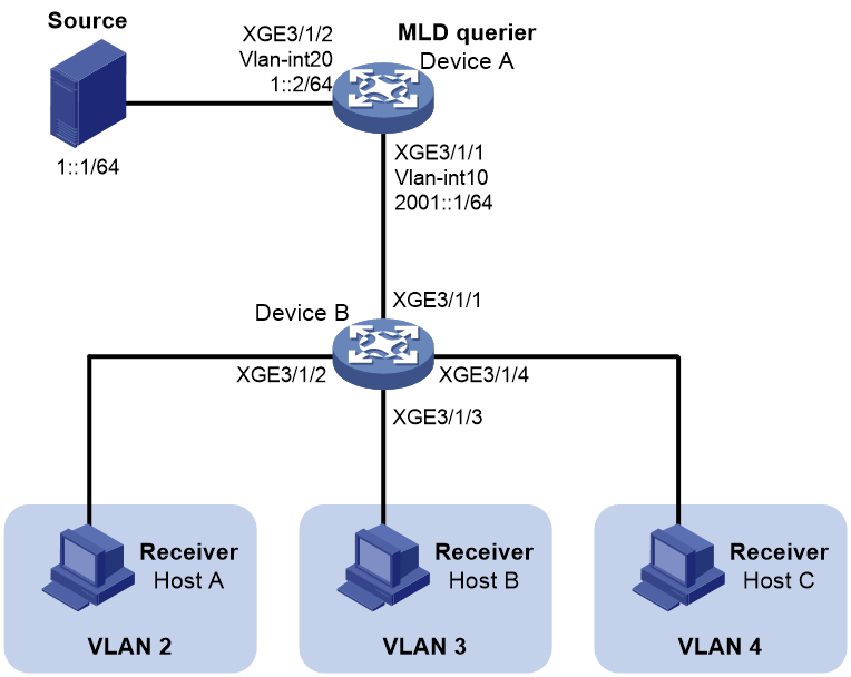
As shown in Figure 4:
· Layer 3 device Device A runs MLD and acts as the MLD querier. Layer 2 device Device B runs MLDv1 snooping.
· The IPv6 multicast source sends IPv6 multicast data to IPv6 multicast group FF1E::101. Receivers Host A, Host B, and Host C belong to VLAN 2, VLAN 3, and VLAN 4, respectively.
Configure a sub-VLAN-based IPv6 multicast VLAN on Device B to meet the following requirements:
· Device A sends the IPv6 multicast data to Device B through the IPv6 multicast VLAN.
· Device B forwards the IPv6 multicast data to the receivers in different user VLANs.
Procedure
1. Configure Device A:
# Enable IPv6 multicast routing.
<DeviceA> system-view
[DeviceA] ipv6 multicast routing
[DeviceA-mrib6] quit
# Create VLAN 20, and assign Ten-GigabitEthernet 3/1/2 to the VLAN.
[DeviceA] vlan 20
[DeviceA-vlan20] port ten-gigabitethernet 3/1/2
[DeviceA-vlan20] quit
# Assign an IPv6 address to VLAN-interface 20, and enable IPv6 PIM-DM on the interface.
[DeviceA] interface vlan-interface 20
[DeviceA-Vlan-interface20] ipv6 address 1::2 64
[DeviceA-Vlan-interface20] ipv6 pim dm
[DeviceA-Vlan-interface20] quit
# Create VLAN 10.
[DeviceA] vlan 10
[DeviceA-vlan10] quit
# Configure Ten-GigabitEthernet 3/1/1 as a hybrid port, and assign the port to VLAN 10 as a tagged VLAN member.
[DeviceA] interface ten-gigabitethernet 3/1/1
[DeviceA-Ten-GigabitEthernet3/1/1] port link-type hybrid
[DeviceA-Ten-GigabitEthernet3/1/1] port hybrid vlan 10 tagged
[DeviceA-Ten-GigabitEthernet3/1/1] quit
# Assign an IPv6 address to VLAN-interface 10, and enable MLD on the interface.
[DeviceA] interface vlan-interface 10
[DeviceA-Vlan-interface10] ipv6 address 2001::1 64
[DeviceA-Vlan-interface10] mld enable
[DeviceA-Vlan-interface10] quit
2. Configure Device B:
# Enable MLD snooping globally.
<DeviceB> system-view
[DeviceB] mld-snooping
[DeviceB-mld-snooping] quit
# Create VLAN 2, assign Ten-GigabitEthernet 3/1/2 to the VLAN, and enable MLD snooping for the VLAN.
[DeviceB] vlan 2
[DeviceB-vlan2] port ten-gigabitethernet 3/1/2
[DeviceB-vlan2] mld-snooping enable
[DeviceB-vlan2] quit
# Create VLAN 3, assign Ten-GigabitEthernet 3/1/3 to the VLAN, and enable MLD snooping for the VLAN.
[DeviceB] vlan 3
[DeviceB-vlan3] port ten-gigabitethernet 3/1/3
[DeviceB-vlan3] mld-snooping enable
[DeviceB-vlan3] quit
# Create VLAN 4, assign Ten-GigabitEthernet 3/1/4 to the VLAN, and enable MLD snooping for the VLAN.
[DeviceB] vlan 4
[DeviceB-vlan4] port ten-gigabitethernet 3/1/4
[DeviceB-vlan4] mld-snooping enable
[DeviceB-vlan4] quit
# Create VLAN 10, and enable MLD snooping for the VLAN.
[DeviceB] vlan 10
[DeviceB-vlan10] mld-snooping enable
[DeviceB-vlan10] quit
# Configure Ten-GigabitEthernet 3/1/1 as a hybrid port, and assign the port to VLAN 10 as a tagged VLAN member.
[DeviceB] interface ten-gigabitethernet 3/1/1
[DeviceB-Ten-GigabitEthernet3/1/1] port link-type hybrid
[DeviceB-Ten-GigabitEthernet3/1/1] port hybrid vlan 10 tagged
[DeviceB-Ten-GigabitEthernet3/1/1] quit
# Configure VLAN 10 as an IPv6 multicast VLAN, and assign VLAN 2 through VLAN 4 as sub-VLANs to multicast VLAN 10.
[DeviceB] ipv6 multicast-vlan 10
[DeviceB-ipv6-mvlan-10] subvlan 2 to 4
[DeviceB-ipv6-mvlan-10] quit
Verifying the configuration
# Display information about all IPv6 multicast VLANs on Device B.
[DeviceB] display ipv6 multicast-vlan
Total 1 IPv6 multicast VLANs.
IPv6 multicast VLAN 10:
Sub-VLAN list(3 in total):
2-4
# Display information about IPv6 multicast groups in IPv6 multicast VLANs on Device B.
[DeviceB] display ipv6 multicast-vlan group
Total 1 entries.
IPv6 multicast VLAN 10: Total 1 entries.
(::, FF1E::101)
Sub-VLANs (3 in total):
VLAN 2
VLAN 3
VLAN 4
The output shows that IPv6 multicast group FF1E::101 belongs to IPv6 multicast VLAN 10. IPv6 multicast VLAN 10 contains sub-VLANs VLAN 2 through VLAN 4. Device B will replicate the IPv6 multicast data of VLAN 10 to VLAN 2 through VLAN 4.
