- Table of Contents
-
- 08-IP Multicast Configuration Guide
- 00-Preface
- 01-Multicast overview
- 02-IGMP snooping configuration
- 03-PIM snooping configuration
- 04-Multicast VLAN configuration
- 05-Multicast routing and forwarding configuration
- 06-IGMP configuration
- 07-PIM configuration
- 08-MSDP configuration
- 09-Multicast VPN configuration
- 10-MLD snooping configuration
- 11-IPv6 PIM snooping configuration
- 12-IPv6 multicast VLAN configuration
- 13-IPv6 multicast routing and forwarding configuration
- 14-MLD configuration
- 15-IPv6 PIM configuration
- Related Documents
-
| Title | Size | Download |
|---|---|---|
| 03-PIM snooping configuration | 172.19 KB |
Restrictions and guidelines: PIM snooping configuration
PIM snooping tasks at a glance
Setting the aging time for global ports after an active/standby switchover
Display and maintenance commands for PIM snooping
PIM snooping configuration examples
Example: Configuring PIM snooping
PIM snooping does not work on a Layer 2 device
Configuring PIM snooping
About PIM snooping
PIM snooping runs on Layer 2 devices. It works with IGMP snooping to analyze received PIM messages, and adds the ports that are interested in specific multicast data to a PIM snooping routing entry. In this way, the multicast data can be forwarded to only the ports that are interested in the data.
Figure 1 Multicast packet transmission without or with PIM snooping
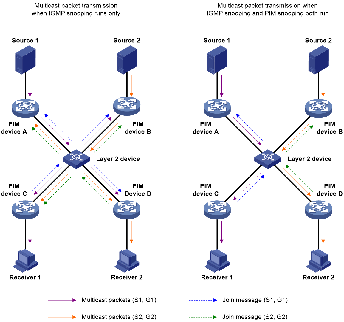
As shown in Figure 1, Source 1 sends multicast data to multicast group G1, and Source 2 sends multicast data to multicast group G2. Receiver 1 belongs to G1, and Receiver 2 belongs to G2. The Layer 2 switch's interfaces that connect to the PIM routers are in the same VLAN or VSI.
· When the Layer 2 switch runs only IGMP snooping, it performs the following actions:
a. Maintains the router ports according to the received PIM hello messages that PIM routers send.
b. Floods all other types of received PIM messages except PIM hello messages in the VLAN or VSI.
c. Forwards all multicast data to all router ports in the VLAN or VSI.
Each PIM router in the VLAN, whether interested in the multicast data or not, can receive all multicast data and all PIM messages except PIM hello messages.
· When the Layer 2 switch runs both IGMP snooping and PIM snooping, it performs the following actions:
a. Examines whether a PIM router is interested in the multicast data addressed to a multicast group according to the received PIM messages that the router sends.
b. Adds only the ports that connect to the router and are interested in the data to a PIM snooping routing entry.
c. Forwards PIM messages and multicast data to only the routers that are interested in the data, which saves network bandwidth.
For more information about IGMP snooping and the router port, see "Configuring IGMP snooping."
Restrictions and guidelines: PIM snooping configuration
VSI-based PIM snooping is available only for the following cards:
|
Card category |
Cards |
|
CEPC |
NP5 cards-CEPC |
|
CSPC |
FPGA cards-CSPC |
|
CSPEX |
NP5 cards-CSPEX, FPGA cards-CSPEX |
|
SPEX |
FPGA cards-SPEX |
|
SPE |
NP5 cards-SPE |
Make sure the maximum size of a PIM join or prune message is smaller than the path MTU of devices connected to PIM snooping devices. Otherwise, fragmented PIM join or prune messages prevent PIM snooping from correctly forwarding multicast data. For more information about setting the maximum size of a join or prune message, see "Configuring PIM."
PIM snooping is supported only for PIM-SM and PIM-SSM. As a best practice, do not configure PIM snooping for PIM-DM. For more information about PIM, see "Configuring PIM."
After you configure PIM snooping for a VLAN or VSI, PIM snooping takes effect only on ports that belong to the VLAN or VSI.
PIM snooping tasks at a glance
To configure PIM snooping, perform the following tasks:
2. (Optional.) Setting the aging time for global ports after an active/standby switchover
¡ Setting the aging time for global neighbor ports after an active/standby switchover
Enabling PIM snooping
1. Enter system view.
system-view
2. Enable IGMP snooping globally and enter IGMP-snooping view.
igmp-snooping
By default, IGMP snooping is disabled.
For more information about this command, see IP Multicast Command Reference.
3. Return to system view.
quit
4. Enter VLAN view or VSI view.
¡ Enter VLAN view.
vlan vlan-id
¡ Enter VSI view.
vsi vsi-name
5. Enable IGMP snooping for the VLAN or VSI.
igmp-snooping enable
By default, IGMP snooping is disabled in a VLAN or VSI.
For more information about this command, see IP Multicast Command Reference.
6. Enable PIM snooping for the VLAN or VSI.
pim-snooping enable
By default, PIM snooping is disabled in a VLAN or VSI.
Setting the aging time for global ports after an active/standby switchover
About this task
A global port is a virtual port on the active MPU, such as a Layer 2 aggregate interface, AC, N-PW, and U-PWs). A global port that acts as a neighbor port, downstream port, or router port is called a global neighbor port, global downstream port, and global router port, respectively.
Perform this task to decrease Layer 2 multicast data interruption caused by the aging of PIM snooping entries after an active/standby switchover.
Restrictions and guidelines
For a global neighbor port, the set aging time does not take effect when the port receives a PIM hello message after an active/standby switchover. The aging time for the port is determined by the aging time in the PIM hello message.
For a global router port or global downstream port, the set aging time does not take effect when the port receives a PIM join message after an active/standby switchover. The aging time for the port is determined by the aging time in the PIM join message.
Setting the aging time for global neighbor ports after an active/standby switchover
1. Enter system view.
system-view
2. Enter VLAN view or VSI view.
¡ Enter VLAN view.
vlan vlan-id
¡ Enter VSI view.
vsi vsi-name
3. Set the aging time for global neighbor ports after an active/standby switchover.
pim-snooping graceful-restart neighbor-aging-time seconds
By default, the aging time for global neighbor ports after an active/standby switchover is 105 seconds.
Setting the aging time for global downstream ports and global router ports after an active/standby switchover
1. Enter system view.
system-view
2. Enter VLAN view or VSI view.
¡ Enter VLAN view.
vlan vlan-id
¡ Enter VSI view.
vsi vsi-name
3. Set the aging time for global downstream ports and global router ports after an active/standby switchover.
pim-snooping graceful-restart join-aging-time seconds
By default, the aging time for downstream ports and global router ports after an active/standby switchover is 210 seconds.
Display and maintenance commands for PIM snooping
Execute display commands in any view and reset commands in user view.
|
Task |
Command |
|
Display PIM snooping neighbor information. |
In standalone mode: display pim-snooping neighbor [ vlan vlan-id | vsi vsi-name ] [ verbose ] [ slot slot-number ] In IRF mode: display pim-snooping neighbor [ vlan vlan-id | vsi vsi-name ] [ verbose ] [ chassis chassis-number slot slot-number ] |
|
Display PIM snooping router port information. |
In standalone mode: display pim-snooping router-port [ vlan vlan-id | vsi vsi-name ] [ slot slot-number ] In IRF mode: display pim-snooping router-port [ vlan vlan-id | vsi vsi-name ] [ chassis chassis-number slot slot-number ] |
|
Display PIM snooping routing entries. |
In standalone mode: display pim-snooping routing-table [ vlan vlan-id | vsi vsi-name ] [ verbose ] [ slot slot-number ] In IRF mode: display pim-snooping routing-table [ vlan vlan-id | vsi vsi-name ] [ verbose ] [ chassis chassis-number slot slot-number ] |
|
Display statistics for the PIM messages learned through PIM snooping. |
display pim-snooping statistics |
|
Clear statistics for the PIM messages learned through PIM snooping. |
reset pim-snooping statistics |
PIM snooping configuration examples
Example: Configuring PIM snooping
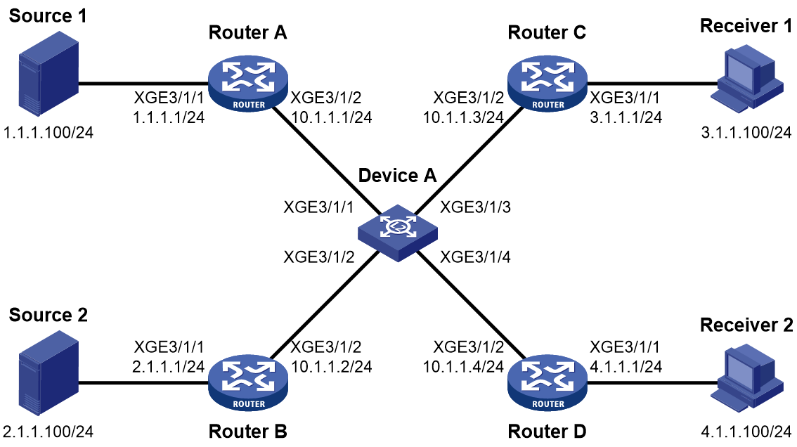
Network configuration
As shown in Figure 2:
· OSPF runs on the network.
· Source 1 and Source 2 send multicast data to multicast groups 224.1.1.1 and 225.1.1.1, respectively.
· Receiver 1 and Receiver 2 belong to multicast groups 224.1.1.1 and 225.1.1.1, respectively.
· Router C and Router D run IGMP on Ten-GigabitEthernet 3/1/1. Router A, Router B, Router C, and Router D run PIM-SM.
· Ten-GigabitEthernet 3/1/2 on Router A acts as a C-BSR and a C-RP.
Configure IGMP snooping and PIM snooping on Device A. Then, Device A forwards PIM protocol packets and multicast data packets only to the routers that are connected to receivers.
Procedure
1. Assign an IP address and subnet mask to each interface, as shown in Figure 2. (Details not shown.)
2. Configure OSPF on the routers. (Details not shown.)
3. Configure Router A:
# Enable IP multicast routing.
<RouterA> system-view
[RouterA] multicast routing
[RouterA-mrib] quit
# Enable PIM-SM on each interface.
[RouterA] interface ten-gigabitethernet 3/1/1
[RouterA-Ten-GigabitEthernet3/1/1] pim sm
[RouterA-Ten-GigabitEthernet3/1/1] quit
[RouterA] interface ten-gigabitethernet 3/1/2
[RouterA-Ten-GigabitEthernet3/1/2] pim sm
[RouterA-Ten-GigabitEthernet3/1/2] quit
# Set the maximum size of a join or prune message to 1400 bytes, and configure Ten-GigabitEthernet 3/1/2 as a C-BSR and a C-RP.
[RouterA] pim
[RouterA-pim] jp-pkt-size 1400
[RouterA-pim] c-bsr 10.1.1.1
[RouterA-pim] c-rp 10.1.1.1
[RouterA-pim] quit
4. Configure Router B:
# Enable IP multicast routing.
<RouterB> system-view
[RouterB] multicast routing
[RouterB-mrib] quit
# Enable PIM-SM on each interface.
[RouterB] interface ten-gigabitethernet 3/1/1
[RouterB-Ten-GigabitEthernet3/1/1] pim sm
[RouterB-Ten-GigabitEthernet3/1/1] quit
[RouterB] interface ten-gigabitethernet 3/1/2
[RouterB-Ten-GigabitEthernet3/1/2] pim sm
[RouterB-Ten-GigabitEthernet3/1/2] quit
# Set the maximum size of a join or prune message to 1400 bytes.
[RouterB] pim
[RouterB-pim] jp-pkt-size 1400
5. Configure Router C:
# Enable IP multicast routing.
<RouterC> system-view
[RouterC] multicast routing
[RouterC-mrib] quit
# Enable IGMP on Ten-GigabitEthernet 3/1/1.
[RouterC] interface ten-gigabitethernet 3/1/1
[RouterC-Ten-GigabitEthernet3/1/1] igmp enable
[RouterC-Ten-GigabitEthernet3/1/1] quit
# Enable PIM-SM on Ten-GigabitEthernet 3/1/2.
[RouterC] interface ten-gigabitethernet 3/1/2
[RouterC-Ten-GigabitEthernet3/1/2] pim sm
[RouterC-Ten-GigabitEthernet3/1/2] quit
# Set the maximum size of a join or prune message to 1400 bytes.
[RouterC] pim
[RouterC-pim] jp-pkt-size 1400
6. Configure Router D:
# Enable IP multicast routing.
<RouterD> system-view
[RouterD] multicast routing
[RouterD-mrib] quit
# Enable IGMP on Ten-GigabitEthernet 3/1/1.
[RouterD] interface ten-gigabitethernet 3/1/1
[RouterD-Ten-GigabitEthernet3/1/1] igmp enable
[RouterD-Ten-GigabitEthernet3/1/1] quit
# Enable PIM-SM on Ten-GigabitEthernet 3/1/2.
[RouterD] interface ten-gigabitethernet 3/1/2
[RouterD-Ten-GigabitEthernet3/1/2] pim sm
[RouterD-Ten-GigabitEthernet3/1/2] quit
# Set the maximum size of a join or prune message to 1400 bytes.
[RouterD] pim
[RouterD-pim] jp-pkt-size 1400
7. Configure Device A:
# Enable IGMP snooping globally.
<DeviceA> system-view
[DeviceA] igmp-snooping
[DeviceA-igmp-snooping] quit
# Create VLAN 100, and assign Ten-GigabitEthernet 3/1/1 through Ten-GigabitEthernet 3/1/4 to the VLAN.
[DeviceA] vlan 100
[DeviceA-vlan100] port ten-gigabitethernet 3/1/1 to ten-gigabitethernet 3/1/4
# Enable IGMP snooping and PIM snooping for VLAN 100.
[DeviceA-vlan100] igmp-snooping enable
[DeviceA-vlan100] pim-snooping enable
[DeviceA-vlan100] quit
Verifying the configuration
# On Device A, display PIM snooping neighbor information for VLAN 100.
[DeviceA] display pim-snooping neighbor vlan 100
Total 4 neighbors.
VLAN 100: Total 4 neighbors.
10.1.1.1
Slots (0 in total):
Ports (1 in total):
XGE3/1/1 (00:32:43)
10.1.1.2
Slots (0 in total):
Ports (1 in total):
XGE3/1/2 (00:32:43)
10.1.1.3
Slots (0 in total):
Ports (1 in total):
XGE3/1/3 (00:32:43)
10.1.1.4
Slots (0 in total):
Ports (1 in total):
XGE3/1/4 (00:32:43)
The output shows that Router A, Router B, Router C, and Router D are PIM snooping neighbors.
# On Device A, display PIM snooping routing entries for VLAN 100.
[DeviceA] display pim-snooping routing-table vlan 100
Total 2 entries.
FSM Flag: NI-no info, J-join, PP-prune pending
VLAN 100: Total 2 entries.
(*, 224.1.1.1)
Upstream neighbor: 10.1.1.1
Upstream Slots (0 in total):
Upstream Ports (1 in total):
XGE3/1/1
Downstream Slots (0 in total):
Downstream Ports (1 in total):
XGE3/1/3
Expires: 00:03:01, FSM: J
(*, 225.1.1.1)
Upstream neighbor: 10.1.1.2
Upstream Slots (0 in total):
Upstream Ports (1 in total):
XGE3/1/2
Downstream Slots (0 in total):
Downstream Ports (1 in total):
XGE3/1/4
Expires: 00:03:11, FSM: J
The output shows the following information:
· Device A will forward the multicast data intended for multicast group 224.1.1.1 only to Router C.
· Device A will forward the multicast data intended for multicast group 225.1.1.1 only to Router D.
Troubleshooting PIM snooping
PIM snooping does not work on a Layer 2 device
Symptom
PIM snooping does not work on a Layer 2 device.
Solution
To resolve the issue:
1. Use the display current-configuration command to display information about IGMP snooping and PIM snooping.
2. If IGMP snooping is not enabled, enable IGMP snooping globally, and then enable IGMP snooping and PIM snooping for the VLAN or VSI.
3. If PIM snooping is not enabled, enable PIM snooping for the VLAN or VSI.
4. If the issue persists, contact H3C Support.
