- Table of Contents
-
- 08-IP Multicast Configuration Guide
- 00-Preface
- 01-Multicast overview
- 02-IGMP snooping configuration
- 03-PIM snooping configuration
- 04-Multicast VLAN configuration
- 05-Multicast routing and forwarding configuration
- 06-IGMP configuration
- 07-PIM configuration
- 08-MSDP configuration
- 09-Multicast VPN configuration
- 10-MLD snooping configuration
- 11-IPv6 PIM snooping configuration
- 12-IPv6 multicast VLAN configuration
- 13-IPv6 multicast routing and forwarding configuration
- 14-MLD configuration
- 15-IPv6 PIM configuration
- Related Documents
-
| Title | Size | Download |
|---|---|---|
| 06-IGMP configuration | 604.76 KB |
Contents
Configuring basic IGMP features
Configuring a static group member
Configuring a multicast group policy
Configuring IGMP query and response parameters
Enabling fast-leave processing
Prerequisites for configuring IGMP proxying
Enabling multicast forwarding on a non-querier interface
Configuring multicast load splitting for IGMP proxy interfaces
Configuring multicast access control
Restrictions and guidelines for multicast access control
Enabling multicast access control
Configuring an IGMP user access policy
Enabling per-session multicast forwarding
Configuring VLAN tagging for multicast packets
Configuring a VLAN-based static group member
Enabling IGMP attack defense for IPoE access
Configuring source MAC-based IGMP suppression to prevent IGMP attacks
Configuring interface-based IGMP suppression to prevent IGMP attacks
Configuring source IP-based IGMP suppression to prevent IGMP attacks
Configuring IGMP host tracking
Configuring global IGMP host tracking
Configuring IGMP host tracking on an interface
Enabling SNMP notifications for IGMP
Enabling log message suppression for IGMP
Configuring IP unnumbered for IGMP
Display and maintenance commands for IGMP
Example: Configuring basic IGMP features
Example: Configuring IGMP SSM mapping
Example: Configuring IGMP proxying
Example: Configuring PPPoE-based multicast access control
Example: Configuring IPoE-based multicast access control
No membership information on the receiver-side device
Inconsistent membership information on the devices on the same subnet
Configuring IGMP
About IGMP
Internet Group Management Protocol (IGMP) establishes and maintains the multicast group memberships between a Layer 3 multicast device and the hosts on the directly connected subnet.
IGMP versions
IGMP has the following versions:
· IGMPv1 (defined by RFC 1112).
· IGMPv2 (defined by RFC 2236).
· IGMPv3 (defined by RFC 3376).
All IGMP versions support the ASM model. IGMPv3 can directly implement the SSM model. IGMPv1 and IGMPv2 must work with the IGMP SSM mapping feature to implement the SSM model. For more information about the ASM and SSM models, see "Multicast overview."
IGMPv1 overview
IGMPv1 manages multicast group memberships based on the query and response mechanism.
All devices that run IGMP on the same subnet can get IGMP membership report messages (called reports) from hosts. However, only one device can act as the IGMP querier to send IGMP query messages (called queries). The querier election mechanism determines which device acts as the IGMP querier on the subnet.
In IGMPv1, the DR elected by the multicast routing protocol (such as PIM) acts as the IGMP querier. For more information about DR, see "Configuring PIM."
Figure 1 IGMP queries and reports
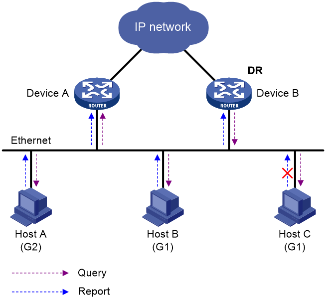
As shown in Figure 1, Host B and Host C are interested in the multicast data addressed to the multicast group G1. Host A is interested in the multicast data addressed to G2. The following process describes how the hosts join the multicast groups and how the IGMP querier (Device B in Figure 1) maintains the multicast group memberships:
1. The hosts send unsolicited IGMP reports to the multicast groups they want to join without having to wait for the IGMP queries.
2. The IGMP querier periodically multicasts IGMP queries (with the destination address of 224.0.0.1) to all hosts and devices on the local subnet.
3. After receiving a query message, the host whose report delay timer expires first sends an IGMP report to multicast group G1 to announce its membership for G1. In this example, Host B sends the report message. After receiving the report from Host B, Host C suppresses its own report for G1.
Because IGMP devices already know that G1 has a minimum of one member, other members do not need to report their memberships. This mechanism, known as the host IGMP report suppression, helps reduce traffic on the local subnet.
4. At the same time, Host A sends a report to the multicast group G2 after receiving a query.
5. Through the query and response process, the IGMP devices (Device A and Device B) determine that the local subnet has members of G1 and G2. The multicast routing protocol (PIM, for example) on the devices generates (*, G1) and (*, G2) multicast forwarding entries, where asterisk (*) represents any multicast source. These entries are the basis for subsequent multicast forwarding.
6. When the multicast data addressed to G1 or G2 reaches an IGMP device, the device looks up the multicast forwarding table. Based on the (*, G1) or (*, G2) entries, the device forwards the multicast data to the local subnet. Then, the receivers on the subnet can receive the data.
IGMPv1 does not define a leave group message (often called a leave message). When an IGMPv1 host is leaving a multicast group, it stops sending reports to that multicast group. If the subnet has no members for a multicast group, the IGMP devices will not receive any report addressed to that multicast group. In this case, the devices clear the information for that multicast group after a period of time.
IGMPv2 enhancements
Backwards-compatible with IGMPv1, IGMPv2 has introduced a querier election mechanism and a leave-group mechanism.
Querier election mechanism
In IGMPv1, the DR elected by the Layer 3 multicast routing protocol (such as PIM) acts as the querier.
IGMPv2 introduced an independent querier election mechanism. The querier election process is as follows:
1. Initially, every IGMPv2 device assumes itself to be the querier. Each device sends IGMP general query messages (called general queries) to all hosts and devices on the local subnet. The destination address is 224.0.0.1.
2. After receiving a general query, every IGMPv2 device compares the source IP address of the query with its own interface address. The device with the lowest IP address becomes the querier. All the other IGMPv2 devices become non-queriers.
3. All the non-queriers start the other querier present timer. If a device receives an IGMP query from the querier before the timer expires, it resets this timer. Otherwise, the device considers that the querier has timed out. In this case, the device initiates a new querier election process.
"Leave group" mechanism
In IGMPv1, when a host leaves a multicast group, it does not send any notification to the multicast devices. The multicast devices determine whether a group has members by using the maximum response time. This adds to the leave latency.
In IGMPv2, when a host is leaving a multicast group, the following process occurs:
1. The host sends a leave message to all devices on the local subnet. The destination address of leave messages is 224.0.0.2.
2. After receiving the leave message, the querier sends a configurable number of IGMP group-specific queries to the group that the host is leaving. Both the destination address field and the group address field of the message are the address of the multicast group that is being queried.
3. One of the remaining members (if any on the subnet) in the group should send a report within the maximum response time advertised in the group-specific queries.
4. If the querier receives a report for the group before the maximum response timer expires, it maintains the memberships for the group. Otherwise, the querier assumes that the local subnet has no member hosts for the group and stops maintaining the memberships for the group.
IGMPv3 enhancements
IGMPv3 is based on and is compatible with IGMPv1 and IGMPv2. It enhances the control capabilities of hosts and the query and report capabilities of IGMP devices.
Enhancements in control capability of hosts
IGMPv3 introduced two source filtering modes (Include and Exclude). These modes allow a host to receive or reject multicast data from the specified multicast sources. When a host joins a multicast group, one of the following occurs:
· If the host expects to receive multicast data from specific sources like S1, S2, …, it sends a report with the Filter-Mode denoted as "Include Sources (S1, S2, …)."
· If the host expects to reject multicast data from specific sources like S1, S2, …, it sends a report with the Filter-Mode denoted as "Exclude Sources (S1, S2, …)."
As shown in Figure 2, the network has two multicast sources: Source 1 (S1) and Source 2 (S2). Both of these sources can send multicast data to the multicast group G. Host B wants to receive the multicast data addressed to G from Source 1 but not from Source 2.
Figure 2 Flow paths of source-and-group-specific multicast traffic
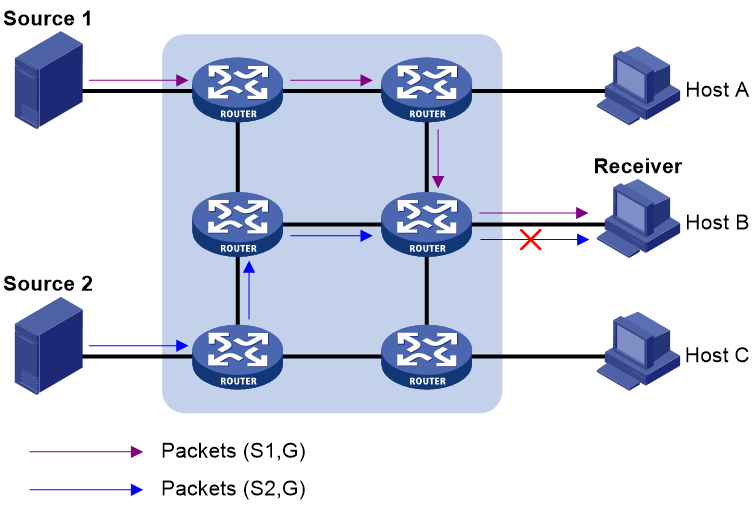
In IGMPv1 or IGMPv2, Host B cannot select multicast sources when it joins the multicast group G. The multicast streams from both Source 1 and Source 2 flow to Host B whether or not it needs them.
In IGMPv3, Host B can explicitly express that it needs to receive multicast data destined to the multicast group G from Source 1 but not from Source 2.
Enhancements in query and report capabilities
IGMPv3 introduces IGMP group-and-source queries and IGMP reports carrying group records.
· Query message carrying the source addresses
IGMPv3 is compatible with IGMPv1 and IGMPv2 and supports IGMP general queries and IGMP group-specific queries. It also introduces IGMP group-and-source-specific queries.
¡ A general query does not carry a group address or a source address.
¡ A group-specific query carries a group address, but no source address.
¡ A group-and-source-specific query carries a group address and one or more source addresses.
· Reports containing multiple group records
Unlike an IGMPv1 or IGMPv2 report, an IGMPv3 report is destined to 224.0.0.22 and contains one or more group records. Each group record contains a multicast group address and a multicast source address list.
Group records include the following categories:
¡ IS_IN—The current filtering mode is Include. The report sender requests the multicast data only from the sources specified in the Source Address field.
¡ IS_EX—The current filtering mode is Exclude. The report sender requests the multicast data from any sources except those specified in the Source Address field.
¡ TO_IN—The filtering mode has changed from Exclude to Include.
¡ TO_EX—The filtering mode has changed from Include to Exclude.
¡ ALLOW—The Source Address field contains a list of additional sources from which the receiver wants to obtain data. If the current filtering mode is Include, these sources are added to the multicast source list. If the current filtering mode is Exclude, these sources are deleted from the multicast source list.
¡ BLOCK—The Source Address field contains a list of the sources from which the receiver no longer wants to obtain data. If the current filtering mode is Include, these sources are deleted from the multicast source list. If the current filtering mode is Exclude, these sources are added to the multicast source list.
IGMP SSM mapping
An IGMPv3 host can explicitly specify multicast sources in its IGMPv3 reports. From the reports, the IGMP device can obtain the multicast source addresses and directly provide the SSM service. However, an IGMPv1 or IGMPv2 host cannot specify multicast sources in its IGMPv1 or IGMPv2 reports.
The IGMP SSM mapping feature enables the IGMP device to provide SSM support for IGMPv1 or IGMPv2 hosts. The device translates (*, G) in IGMPv1 or IGMPv2 reports into (G, INCLUDE, (S1, S2...)) based on the configured IGMP SSM mappings.
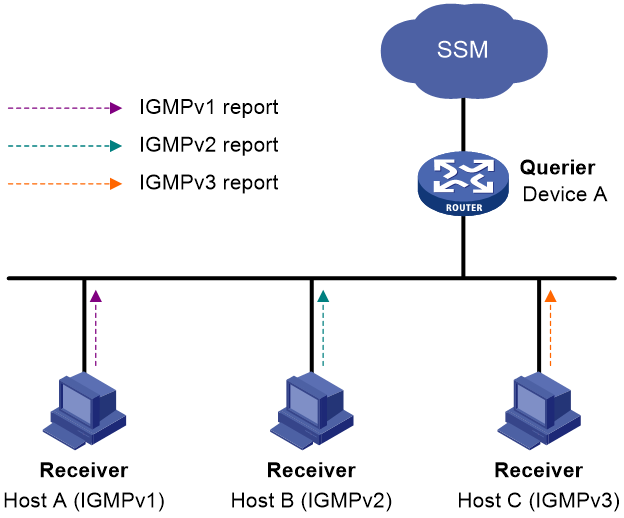
As shown in Figure 3, on an SSM network, Host A, Host B, and Host C run IGMPv1, IGMPv2, and IGMPv3, respectively. To provide the SSM service for Host A and Host B, you must configure the IGMP SSM mapping feature on Device A.
After IGMP SSM mappings are configured, Device A checks the multicast group address G in the received IGMPv1 or IGMPv2 report, and performs the following operations:
· If G is not in the SSM group range, Device A provides the ASM service.
· If G is in the SSM group range but does not match any IGMP SSM mapping, Device A drops the report.
· If G is in the SSM group range and matches IGMP SSM mappings, Device A translates (*, G) in the report into (G, INCLUDE, (S1, S2...)) to provide SSM services.
|
NOTE: The IGMP SSM mapping feature does not process IGMPv3 reports. |
For more information about SSM group ranges, see "Configuring PIM."
IGMP proxying
As shown in Figure 4, in a simple tree-shaped topology, it is not necessary to run multicast routing protocols, such as PIM, on edge devices. Instead, you can configure IGMP proxying on these devices. With IGMP proxying configured, the edge device acts as an IGMP proxy:
· For the upstream IGMP querier, the IGMP proxy device acts as a host.
· For the downstream receiver hosts, the IGMP proxy device acts as an IGMP querier.
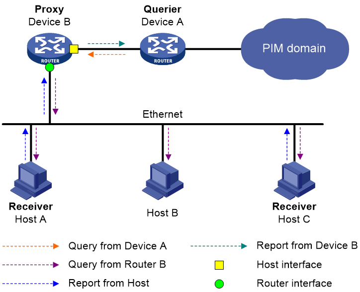
The following types of interfaces are defined in IGMP proxying:
· Host interface—An interface that is in the direction toward the root of the multicast forwarding tree. A host interface acts as a receiver host that is running IGMP. IGMP proxying must be enabled on this interface. This interface is also called the "proxy interface."
· Router interface—An interface that is in the direction toward the leaf of the multicast forwarding tree. A router interface acts as a router that is running IGMP. IGMP must be configured on this interface.
An IGMP proxy device maintains a group membership database, which stores the group memberships on all the router interfaces. The host interfaces and router interfaces perform actions based on this membership database.
· The host interfaces respond to queries according to the membership database or send join/leave messages when the database changes.
· The router interfaces participate in the querier election, send queries, and maintain memberships based on received IGMP reports.
Multicast access control
IP multicast allows users to join any multicast group in order to receive multicast data. In some carrier's services, such as IPTV, users are authenticated and authorized before accessing multicast data.
Multicast access control provides a mechanism to control a user's access to multicast data by limiting the multicast groups that the user can join. When a user logs in, the BRAS downloads the access authorization profile of the user. Based on the authorization profile, the BRAS accepts or denies the reports from the user to join multicast groups.
IGMP support for VPNs
IGMP maintains group memberships on a per-interface basis. After receiving an IGMP message on an interface, IGMP processes the packet within the VPN to which the interface belongs. IGMP only communicates with other multicast protocols within the same VPN instance.
Protocols and standards
· RFC 1112, Host Extensions for IP Multicasting
· RFC 2236, Internet Group Management Protocol, Version 2
· RFC 3376, Internet Group Management Protocol, Version 3
IGMP tasks at a glance
To configure IGMP, perform the following tasks:
2. (Optional.) Configuring basic IGMP features
¡ Configuring a static group member
¡ Configuring a multicast group policy
3. (Optional.) Adjusting IGMP performance
¡ Configuring IGMP query and response parameters
¡ Enabling fast-leave processing
4. (Optional.) Configuring IGMP SSM mappings
5. (Optional.) Configuring IGMP proxying
¡ Enabling multicast forwarding on a non-querier interface
¡ Configuring multicast load splitting for IGMP proxy interfaces
6. (Optional.) Configuring multicast access control
¡ Enabling multicast access control
¡ Configuring an IGMP user access policy
¡ Enabling per-session multicast forwarding
¡ Configuring VLAN tagging for multicast packets
¡ Configuring a VLAN-based static group member
7. (Optional.) Enabling IGMP attack defense for IPoE access
8. (Optional.) Configuring source MAC-based IGMP suppression to prevent IGMP attacks
9. (Optional.) Configuring interface-based IGMP suppression to prevent IGMP attacks
10. (Optional.) Configuring source IP-based IGMP suppression to prevent IGMP attacks
11. (Optional.) Configuring IGMP host tracking
12. (Optional.) Enabling SNMP notifications for IGMP
13. (Optional.) Enabling IGMP logging
14. (Optional.) Enabling log message suppression for IGMP
15. (Optional.) Configuring IP unnumbered for IGMP
Prerequisites for IGMP
Before you configure IGMP, you must configure any unicast routing protocol so that all devices can interoperate at the network layer.
Enabling IGMP
Restrictions and guidelines
Enable IGMP on interfaces where the multicast group memberships are established and maintained.
Procedure
1. Enter system view.
system-view
2. Enable IP multicast routing and enter MRIB view.
multicast routing [ vpn-instance vpn-instance-name ]
By default, IP multicast routing is disabled.
For more information about this command, see IP Multicast Command Reference.
3. Return to system view.
quit
4. Enter interface view.
interface interface-type interface-number
5. Enable IGMP.
igmp enable
By default, IGMP is disabled.
Configuring basic IGMP features
Specifying an IGMP version
system-view
2. Enter interface view.
interface interface-type interface-number
3. Specify an IGMP version on the interface.
igmp version version-number
By default, the IGMP version on an interface is IGMPv2.
|
|
CAUTION: For IGMP to operate correctly, specify the same IGMP version for all devices on the same subnet. |
Configuring a static group member
About this task
You can configure an interface as a static group member of multicast groups. Then, the interface can always receive multicast data addressed to the specified multicast groups.
A static group member does not respond to IGMP queries. When you complete or cancel this configuration on an interface, the interface does not send an unsolicited IGMP report or leave message.
Restrictions and guidelines
The interface to be configured as a static group member has the following restrictions:
· If the interface is IGMP and PIM-SM enabled, it must be a PIM-SM DR.
· If the interface is IGMP enabled but not PIM-SM enabled, it must be an IGMP querier.
For more information about PIM-SM and DR, see "Configuring PIM."
When you configure an interface as a static group member for multiple multicast groups or multicast sources and groups in batch, follow these restrictions and guidelines:
· Multicast group addresses in different batch configurations can overlap.
· The undo igmp static-group command does not support deleting one multicast group from batch configuration. When you delete a batch configuration, make sure the setting in the undo command match the batch configuration.
· If two batch configurations have the same parameter settings except the setting of the number group-number option, the new configuration takes effect.
Procedure
1. Enter system view.
system-view
2. Enter interface view.
interface interface-type interface-number
3. Configure the interface as a static group member.
igmp static-group group-address [ inc-step-mask { group-mask | group-mask-length } number group-number ] [ source source-address ]
Configuring a multicast group policy
About this task
This feature enables an interface to filter IGMP reports by using an ACL that specifies multicast groups and the optional sources. It is used to control the multicast groups that the hosts attached to an interface can join.
Restrictions and guidelines
This configuration does not take effect on static group members, because static group members do not send IGMP reports.
Procedure
1. Enter system view.
system-view
2. Enter interface view.
interface interface-type interface-number
3. Configure a multicast group policy.
igmp group-policy { ipv4-acl-number | name ipv4-acl-name } [ version-number ]
By default, no multicast group policy exists on an interface. Hosts attached to the interface can join any multicast groups.
Adjusting IGMP performance
Configuring IGMP query and response parameters
About this task
The following are IGMP query and response parameters:
· IGMP querier's robustness variable—Number of times for retransmitting IGMP queries in case of packet loss. A higher robustness variable makes the IGMP querier more robust, but increases the timeout time for multicast groups.
· IGMP startup query interval—Interval at which an IGMP querier sends IGMP general queries at startup.
· IGMP startup query count—Number of IGMP general queries that an IGMP querier sends at startup.
· IGMP general query interval—Interval at which an IGMP querier sends IGMP general queries to check for multicast group members on the network.
· IGMP last member query interval—In IGMPv2, it sets the interval at which a querier sends group-specific queries after receiving a leave message. In IGMPv3, it sets the interval at which a querier sends group-and-source-specific queries after receiving a report that changes multicast source and group mappings.
· IGMP last member query count—In IGMPv2, it sets the number of group-specific queries that a querier sends after receiving a leave message. In IGMPv3, it sets the number of group-and-source-specific queries that a querier sends after receiving a report that changes multicast source and group mappings.
· IGMP maximum response time—Maximum time before a receiver responds with a report to an IGMP general query. This per-group timer is initialized to a random value in the range of 0 to the maximum response time specified in the IGMP query. When the timer value for a group decreases to 0, the receiver sends an IGMP report to the group.
· IGMP other querier present timer—Lifetime for an IGMP querier after a non-querier receives an IGMP general query. If the non-querier does not receive a new query when this timer expires, the non-querier considers that the querier has failed and starts a new querier election.
Restrictions and guidelines
To avoid frequent IGMP querier changes, set the IGMP other querier present timer greater than the IGMP general query interval. In addition, configure the same IGMP other querier present timer for all IGMP devices on the same subnet.
To avoid mistakenly deleting multicast receivers, set the IGMP general query interval greater than the maximum response time for IGMP general queries.
To speed up the response to IGMP queries and avoid simultaneous timer expirations that cause IGMP report traffic bursts, set an appropriate maximum response time.
· For IGMP general queries, the maximum response time is set by the max-response-time command.
· For IGMP group-specific queries and IGMP group-and-source-specific queries, the maximum response time equals the IGMP last member query interval.
The following configurations take effect only on the devices that run IGMPv2 and IGMPv3:
· Maximum response time for IGMP general queries.
· IGMP last member query interval.
· IGMP last member query count.
· IGMP other querier present interval.
You can configure the IGMP query and response parameters globally for all interfaces in IGMP view or for an interface in interface view. The interface-specific configuration takes priority over the global configuration.
Configuring the IGMP query and response parameters globally
1. Enter system view.
system-view
2. Enter IGMP view.
igmp [ vpn-instance vpn-instance-name ]
3. Set the IGMP querier's robustness variable.
robust-count count
By default, the IGMP querier's robustness variable is 2.
4. Set the IGMP startup query interval.
startup-query-interval interval
By default, the IGMP startup query interval is equal to one quarter of the IGMP general query interval.
5. Set the IGMP startup query count.
startup-query-count count
By default, the IGMP startup query count is equal to the IGMP querier's robustness variable.
6. Set the IGMP general query interval.
query-interval interval
By default, the IGMP general query interval is 125 seconds.
7. Set the IGMP last member query interval.
last-member-query-interval interval
By default, the IGMP last member query interval is 1 second.
8. Set the IGMP last member query count.
last-member-query-count count
By default, the IGMP last member query count is equal to the IGMP querier's robustness variable.
9. Set the maximum response time for IGMP general queries.
max-response-time time
By default, the maximum response time for IGMP general queries is 10 seconds.
10. Set the IGMP other querier present timer.
other-querier-present-interval interval
By default, the IGMP other querier
present timer is calculated by using the following formula:
[ IGMP general query interval ] × [ IGMP robustness variable ] + [ maximum
response time for IGMP general queries ] / 2.
Configuring the IGMP query and response parameters on an interface
1. Enter system view.
system-view
2. Enter interface view.
interface interface-type interface-number
3. Set the IGMP querier's robustness variable.
igmp robust-count count
By default, the IGMP querier's robustness variable is 2.
4. Set the IGMP startup query interval.
igmp startup-query-interval interval
By default, the IGMP startup query interval is equal to one quarter of the IGMP general query interval.
5. Set the IGMP startup query count.
igmp startup-query-count count
By default, the IGMP startup query count is equal to the IGMP querier's robustness variable.
6. Set the IGMP general query interval.
igmp query-interval interval
By default, the IGMP general query interval is 125 seconds.
7. Set the IGMP last member query interval.
igmp last-member-query-interval interval
By default, the IGMP last member query interval is 1 second.
8. Set the IGMP last member query count.
igmp last-member-query-count count
By default, the IGMP last member query count is equal to the IGMP querier's robustness variable.
9. Set the maximum response time for IGMP general queries.
igmp max-response-time time
By default, the maximum response time for IGMP general queries is 10 seconds.
10. Set the IGMP other querier present timer.
igmp other-querier-present-interval interval
By default, the IGMP other querier
present timer is calculated by using the following formula:
[ IGMP general query interval ] × [ IGMP robustness variable ] + [ maximum
response time for IGMP general queries ] / 2.
Enabling fast-leave processing
About this task
This feature enables an IGMP querier to send leave notifications to the upstream without sending group-specific or group-and-source-specific queries after receiving a leave message. Use this feature to reduce leave latency and to preserve the network bandwidth.
Restrictions and guidelines
The fast-leave processing configuration takes effect only when the device runs IGMPv2 or IGMPv3.
Procedure
1. Enter system view.
system-view
2. Enter interface view.
interface interface-type interface-number
3. Enable fast-leave processing.
igmp fast-leave [ group-policy ipv4-acl-number ]
By default, fast-leave processing is disabled.
Configuring IGMP SSM mappings
About this task
This feature enables the device to provide SSM services for IGMPv1 or IGMPv2 hosts.
Restrictions and guidelines
This feature does not process IGMPv3 messages. Enable IGMPv3 on the receiver-side interface to ensure that IGMPv3 reports can be processed..
Procedure
1. Enter system view.
system-view
2. Enter IGMP view.
igmp [ vpn-instance vpn-instance-name ]
3. Configure an IGMP SSM mapping.
ssm-mapping source-address { ipv4-acl-number| name ipv4-acl-name }
By default, no IGMP SSM mappings exist.
Configuring IGMP proxying
Prerequisites for configuring IGMP proxying
Before you configure IGMP proxying, determine the router interfaces and host interfaces based on the network topology, and enable IGMP on the router interfaces.
Enabling IGMP proxying
Restrictions and guidelines
Enable IGMP proxying on the receiver-side interfaces.
On an interface enabled with IGMP proxying, only the igmp version command takes effect and other IGMP commands do not take effect.
If you enable both IGMP proxying and a multicast routing protocol (such as PIM or MSDP) on the same device, the multicast routing protocol does not take effect.
In IGMPv1, the DR is elected by PIM and acts as the IGMP querier. Because PIM does not take effect on a proxy device, a router interface running IGMPv1 cannot be elected as the DR. To ensure that the downstream receiver hosts on the router interface can receive multicast data, you must enable multicast forwarding on the interface. For more information, see "Enabling multicast forwarding on a non-querier interface."
An interface enabled with IGMP proxying does not support the IP unnumbered function. For information about this function, see IP addressing in Layer 3—IP Services Configuration Guide.
Procedure
1. Enter system view.
system-view
2. Enter interface view.
interface interface-type interface-number
3. Enable IGMP proxying.
igmp proxying enable
By default, IGMP proxying is disabled.
Enabling multicast forwarding on a non-querier interface
About this task
Typically, only IGMP queriers can forward multicast traffic and non-queriers cannot. This prevents multicast data from being repeatedly forwarded. If a router interface on an IGMP proxy device failed in the querier election, enable multicast forwarding on the interface to forward multicast data to attached receiver hosts.
Restrictions and guidelines
A shared-media network might have multiple IGMP proxies, including one proxy acting as a querier. To avoid duplicate multicast traffic, do not enable multicast forwarding on any of the non-querier IGMP proxies for the network.
Procedure
1. Enter system view.
system-view
2. Enter interface view.
interface interface-type interface-number
3. Enable multicast forwarding on the interface.
igmp proxy forwarding
By default, multicast forwarding is disabled on a non-querier interface.
Configuring multicast load splitting for IGMP proxy interfaces
About this task
If multiple IGMP proxy interfaces exist on the device, only the proxy interface with the highest IP address forwards multicast traffic. You can enable multicast load splitting for IGMP proxy interfaces so that all the proxy interfaces can share multicast traffic.
Procedure
1. Enter system view.
system-view
2. Enter IGMP view.
igmp [ vpn-instance vpn-instance-name ]
3. Enable multicast load splitting for IGMP proxy interfaces.
proxy multipath
By default, multicast load splitting is disabled for IGMP proxy interfaces.
Configuring multicast access control
Restrictions and guidelines for multicast access control
Configure multicast access control only on the BRAS.
In standard system operating mode, this feature is available only for the following cards:
|
Card category |
Cards |
|
CEPC |
NP5 cards-CEPC |
|
CSPEX |
NP5 cards-CSPEX, CSPEX-1802XB, CSPEX-1802X, CSPEX-1812X-E, CSPEX-2304X-G |
|
SPE |
NP5 cards-SPE, RX-SPE200-E |
On a receiver-side interface configured with QinQ termination or ambiguous Dot1q termination, you must execute the igmp join-by-session command to enable per-session multicast forwarding. This restriction is not applicable to PPPoE-based multicast access control. For more information about QinQ termination or ambiguous Dot1q termination, see VLAN termination in Layer 2-LAN Switching Configuration Guide.
Enabling multicast access control
Restrictions and guidelines
Enable this feature on interfaces of the BRAS where you want to control the downstream users' access to multicast traffic.
This feature takes effect only on local online users. Non-local users and offline users are not affected.
Make sure the device does not run IGMPv1. If the device runs IGMPv1, no IGMP querier will be elected.
This feature does not take effect in static VLAN tagging mode.
Procedure
1. Enter system view.
system-view
2. Enter Layer 3 interface view.
¡ Enter Layer 3 Ethernet interface view.
interface interface-type interface-number
¡ Enter Layer 3 Ethernet subinterface view.
interface interface-type interface-number.subnumber
¡ Enter Layer 3 aggregate interface view.
interface route-aggregation interface-number
¡ Enter Layer 3 aggregate subinterface view.
interface route-aggregation interface-number.subnumber
¡ Enter VT interface view.
interface virtual-template number
3. Enable multicast access control.
igmp authorization-enable
By default, multicast access control is disabled.
Configuring an IGMP user access policy
About this task
This feature enables the BRAS to filter IGMP reports by using an ACL that specifies the multicast groups in a user profile. Use this feature to control the multicast groups that an IGMP user can join.
You can also configure a multicast group list on the RADIUS server to achieve the same purpose. A user can join a multicast group if the group is in the group list.
If you specify both a multicast group list and a user access policy, a user can join a multicast group that matches either of them.
Procedure
1. Enter system view.
system-view
2. Enter ISP domain view.
domain name isp-name
For more information about this command, see BRAS Services Command Reference.
3. Configure the default authorization user profile for the ISP domain.
authorization-attribute user-profile profile-name
By default, the default authorization user profile is not configured for an ISP domain.
The authorization user profile configuration on the RADIUS server takes priority over the configuration made in an ISP domain.
For more information about this command, see BRAS Services Command Reference.
4. Return to system view.
quit
5. Enter user profile view.
user-profile profile-name
For more information about this command, see BRAS Services Command Reference.
6. Configure an IGMP user access policy.
igmp access-policy ipv4-acl-number
By default, no IGMP user access policy is configured. IGMP users are not authorized to join any multicast groups.
Enabling per-session multicast forwarding
About this task
By default, the BRAS forwards multicast traffic on a per-interface basis. It sends only one copy of multicast traffic to a downstream interface, and the downstream IGMP snooping device replicates the multicast traffic to each receiver.
If the downstream device does not support IGMP snooping, you can configure the downstream interface on the BRAS to forward multicast traffic on a per-session basis. This allows the BRAS to send a separate copy of the multicast data to each receiver.
Restrictions and guidelines
This configuration automatically deletes the static multicast forwarding entries created by the non-VLAN-based static member group configurations.
Procedure
1. Enter system view.
system-view
2. Enter Layer 3 interface view.
¡ Enter Layer 3 Ethernet interface view.
interface interface-type interface-number
¡ Enter Layer 3 Ethernet subinterface view.
interface interface-type interface-number.subnumber
¡ Enter Layer 3 aggregate interface view.
interface route-aggregation interface-number
¡ Enter Layer 3 aggregate subinterface view.
interface route-aggregation interface-number.subnumber
3. Enable per-session multicast forwarding.
igmp join-by-session [ mode{ both | bras | non-bras }]
By default, per-interface multicast forwarding is enabled.
Configuring VLAN tagging for multicast packets
About this task
If Dot1q or QinQ VLAN termination is configured on a Layer 3 Ethernet subinterface or Layer 3 aggregate subinterface to terminate VLANs, the BRAS device cannot locate VLANs for multicast receivers.
To resolve this issue, configure VLAN tagging for multicast packets on the BRAS device. This feature enables the BRAS device to tag multicast packets with specific VLAN IDs and send them to IGMP snooping-enabled downstream devices. Then, the downstream devices forward the packets to users in the specified VLANs. This feature also saves the bandwidth on the BRAS device.
The device support static and dynamic VLAN tagging modes for multicast packets.
· Static VLAN tagging mode—In this mode, you must specify a VLAN ID used to tag multicast packets on an interface. After a multicast user in this VLAN comes online from this interface, the BRAS device tags multicast packets with the VLAN ID and sends the tagged multicast packets to the downstream device. Then, the downstream device forwards the packets to the user in this VLAN.
· Dynamic VLAN tagging mode—In this mode, the BRAS device dynamically tags multicast packets with the IDs of the VLANs to which online multicast users belong. It duplicates multiple copies of multicast packets, tags each copy with a user VLAN ID, and sends the copies to the downstream device. Then, the downstream device forwards each copy to the users in each VLAN.
Restrictions and guidelines
The igmp join-by-session and igmp user-vlan-aggregation commands are mutually exclusive.
This function does not take effect on PPPoE users.
Procedure
1. Enter system view.
system-view
2. Enter Layer 3 subinterface view.
¡ Enter Layer 3 Ethernet subinterface view.
interface interface-type interface-number.subnumber
¡ Enter Layer 3 aggregate subinterface view.
interface route-aggregation interface-number.subnumber
3. Configure VLAN tagging for multicast packets.
igmp user-vlan-aggregation { dynamic | dot1q vid vlan-id [ second-dot1q vlan-id ] }
By default, the device does not tag multicast packets.
Configuring a VLAN-based static group member
About this task
In access-controlled multicast, multicast packets are VLAN-tagged. When you configure a subinterface on the BRAS as a static group member, you must specify the VLANs to which the subinterface belongs. Otherwise, the subinterface cannot join the multicast group, and the static multicast forwarding entry cannot be created.
Restrictions and guidelines
For a successful, static multicast forwarding entry creation, do not configure the igmp join-by-session or igmp user-vlan-aggregation dot1q command on a subinterface when you configure it as a non-VLAN-based static member interface.
When you configure a subinterface as a VLAN-based static member interface, a static multicast forwarding entry can be created under either of the following conditions:
· Users that belong to the specified VLANs come online if the igmp user-vlan-aggregation command is not configured on the subinterface.
· The VLAN IDs specified in the igmp static-group command are the same as or included in the VLAN IDs specified in the igmp user-vlan-aggregation command configured on the subinterface.
When you configure an interface as a static group member for multiple multicast groups or multicast sources and groups in batch, follow these restrictions and guidelines:
· Multicast group addresses in different batch configurations can overlap.
· The undo igmp static-group command does not support deleting one multicast group from batch configuration. When you delete a batch configuration, make sure the setting in the undo command matches the configuration.
· If two batch configurations have the same parameter settings except the setting of the number group-number option, the new configuration takes effect.
Procedure
1. Enter system view.
system-view
2. Enter Layer 3 subinterface view.
¡ Enter Layer 3 Ethernet subinterface view.
interface interface-type interface-number.subnumber
¡ Enter Layer 3 aggregate subinterface view.
interface route-aggregation interface-number.subnumber
3. Configure the subinterface as a VLAN-based static group member.
igmp static-group group-address [ inc-step-mask { group-mask | group-mask-length } number group-number ] [ source source-address ] { dot1q vid vlan-list | dot1q vid vlan-id second-dot1q vlan-list }
Enabling IGMP attack defense for IPoE access
About this task
For a multicast application in a BRAS system, only online users can join multicast groups to receive multicast data. However, IGMP messages from non-online users are also sent to the CPU for processing. Online users might not be able to join multicast groups because of IGMP attacks from non-online users.
The IGMP attack defense feature enables the device to process only IGMP messages from online users and to discard IGMP messages from non-online users.
The IGMP attack defense feature enables the device to process only IGMP messages from online users and to discard IGMP messages from non-online users.
Restrictions and guidelines
Use this feature only for IPoE users in a BRAS network. For more information about IPoE, see BRAS Services Configuration Guide.
In standard system operating mode, this feature is available only for the following cards:
|
Card category |
Cards |
|
CEPC |
NP5 cards-CEPC |
|
CSPEX |
NP5 cards-CSPEX, CSPEX-1802XB, CSPEX-1802X, CSPEX-1812X-E, CSPEX-2304X-G, CSPEX-2304X-LG |
|
SPE |
NP5 cards-SPE, RX-SPE200-E |
Enable this feature only on an interface that is configured with IPoE access authentication. If an interface is not configured with IPoE authentication, this feature will discard IGMP messages from all users and online users cannot join multicast groups.
Procedure
1. Enter system view.
system-view
2. Enter Layer 3 interface view.
¡ Enter Layer 3 Ethernet interface view.
interface interface-type interface-number
¡ Enter Layer 3 Ethernet subinterface view.
interface interface-type interface-number.subnumber
¡ Enter Layer 3 aggregate interface view.
interface route-aggregation interface-number
¡ Enter Layer 3 aggregate subinterface view.
interface route-aggregation interface-number.subnumber
3. Enable IGMP attack defense.
igmp attack-defense
By default, IGMP attack defense is disabled.
|
|
CAUTION: Enable this feature only on an interface that is configured with IPoE access authentication. If an interface is not configured with IPoE authentication, this feature will discard IGMP messages from all users and online users cannot join multicast groups. |
Configuring source MAC-based IGMP suppression to prevent IGMP attacks
About this task
This feature monitors the number of IGMP packets on a per source MAC basis. With this feature enabled, the device creates a suppression entry upon receiving the first packet from a MAC address. When the number of IGMP packets from this MAC address exceeds the threshold within the check interval, the device determines that the host at the MAC address launches an attack. It starts a suppression aging timer, and drops subsequent IGMP attack packets from this MAC address until the timer expires.
Restrictions and guidelines
In standard system operating mode, this feature is available only for the following cards:
|
Card category |
Cards |
|
CEPC |
NP5 cards-CEPC, NPS400 cards-CEPC |
|
CSPEX |
NP5 cards-CSPEX, NPS400 cards-CSPEX |
|
SPE |
NP5 cards-SPE, NPS400 cards-SPE |
In SDN-WAN system operating mode, this feature is available only for the following cards:
|
Card category |
Cards |
|
CEPC |
NPS400 cards-CEPC |
|
CSPEX |
NPS400 cards-CSPEX |
|
SPE |
NPS400 cards-SPE |
This feature takes effect only on Layer 3 Ethernet interfaces and Layer 3 Ethernet subinterfaces if you enable IGMP snooping globally on the device. IGMP packets received on VLAN interfaces and Layer 2 interfaces (such as Layer 2 aggregate interfaces) are processed at Layer 2.
In multicast applications in a BRAS system, follow these restrictions and guidelines:
· This feature does not take effect on PPPoE users.
· As a best practice, use the igmp attack-defense command enable IGMP attack defense for IPoE users.
Procedure
1. Enter system view.
system-view
2. Enable source MAC-based IGMP suppression.
igmp attack-suppression source-mac enable
By default, source MAC-based IGMP suppression is disabled.
3. Set the threshold for triggering source MAC-based IGMP suppression.
igmp attack-suppression source-mac threshold threshold-value
By default, the threshold is 1000 for triggering source MAC-based IGMP suppression.
4. Set the check interval for source MAC-based IGMP suppression.
igmp attack-suppression source-mac check-interval interval
By default, the check interval is 30 seconds for source MAC-based IGMP suppression.
5. Set the aging time for source MAC-based IGMP suppression entries.
igmp attack-suppression source-mac aging-time time
By default, the aging time is 30 seconds for source MAC-based IGMP suppression entries.
Configuring interface-based IGMP suppression to prevent IGMP attacks
About this task
This feature allows the device to create IGMP suppression entries and count the number of received IGMP packets on a per interface basis. When the number exceeds the threshold within the check interval, the device identifies these packets as attack packets and limits the rate for sending them to the CPU.
Restrictions and guidelines
This feature takes effect only on Layer 3 Ethernet interfaces and Layer 3 Ethernet subinterfaces if you enable IGMP snooping globally on the device. IGMP packets received on VLAN interfaces and Layer 2 interfaces (such as Layer 2 aggregate interfaces) are processed at Layer 2.
In multicast applications in a BRAS system, follow these restrictions and guidelines:
· This feature does not take effect on PPPoE users.
· As a best practice, use the igmp attack-defense command enable IGMP attack defense for IPoE users.
Procedure
1. Enter system view.
system-view
2. Enable interface-based IGMP suppression.
igmp attack-suppression per-interface enable
By default, interface-based IGMP suppression is disabled.
3. Set the threshold for triggering interface-based IGMP suppression.
igmp attack-suppression per-interface threshold threshold-value
By default, the threshold is 6000 for triggering interface-based IGMP suppression.
4. Set the check interval for interface-based IGMP suppression.
igmp attack-suppression per-interface check-interval interval
By default, the check interval is 30 seconds for interface-based IGMP suppression.
5. Set the aging time for interface-based IGMP suppression entries.
igmp attack-suppression per-interface aging-time time
By default, the aging time is 30 seconds for interface-based IGMP suppression entries.
Configuring source IP-based IGMP suppression to prevent IGMP attacks
About this task
This feature monitors the number of IGMP packets on a per source IP basis. With this feature enabled, the device creates a suppression entry upon receiving the first packet from an IP address. When the number of IGMP packets from this IP address exceeds the threshold within the check interval, the device determines that the host at the IP address launches an attack. It starts a suppression aging timer, and drops subsequent IGMP attack packets from this IP address until the timer expires.
Use this feature to prevent IGMP attack packets from occupying too many CPU resources.
Restrictions and guidelines
This feature takes effect only on Layer 3 Ethernet interfaces and Layer 3 Ethernet subinterfaces if you enable IGMP snooping globally on the device. IGMP packets received on VLAN interfaces and Layer 2 interfaces (such as Layer 2 aggregate interfaces) are processed at Layer 2.
In multicast applications in a BRAS system, follow these restrictions and guidelines:
· This feature does not take effect on PPPoE users.
· As a best practice, use the igmp attack-defense command enable IGMP attack defense for IPoE users.
·
Procedure
1. Enter system view.
system-view
2. Enable source IP-based IGMP suppression.
igmp attack-suppression source-ip enable
By default, source IP-based IGMP suppression is disabled.
3. Set the threshold for triggering source IP-based IGMP suppression.
igmp attack-suppression source-ip threshold threshold-value
By default, the threshold is 1000 for triggering source IP-based IGMP suppression.
4. Set the check interval for source IP-based IGMP suppression.
igmp attack-suppression source-ip check-interval interval
By default, the check interval is 30 seconds for source IP-based IGMP suppression.
5. Set the aging time for source IP-based IGMP suppression entries.
igmp attack-suppression source-ip aging-time time
By default, the aging time is 30 seconds for source IP-based IGMP suppression entries.
Configuring IGMP host tracking
About IGMP host tracking
This feature allows the device to record IP addresses, running time, timeout time, and other information about receiver hosts. You can monitor and manage receiver hosts based on the recorded information.
Configuring global IGMP host tracking
Restrictions and guidelines
After you enable IGMP host tracking globally, IGMP host tracking is enabled on all interfaces on the device. If IGMP host tracking is not needed on an interface, disable IGMP host tracking on the interface by using the igmp host-tracking disable command.
For an interface, the interface-specific IGMP host tracking configuration has higher priority than the global configuration.
Procedure
1. Enter system view.
system-view
2. Enter IGMP view.
igmp [ vpn-instance vpn-instance-name ]
3. Enable IGMP host tracking globally.
host-tracking enable
By default, IGMP host tracking is disabled.
4. (Optional.) Execute the following commands in sequence to disable IGMP host tracking on an interface.
a. Return to system view.
quit
b. Enter interface view.
interface interface-type interface-number
c. Disable IGMP host tracking on the interface.
igmp host-tracking disable
By default, the interface-specific IGMP host tracking status is consistent with the global IGMP host tracking status.
Configuring IGMP host tracking on an interface
Restrictions and guidelines
The interface-specific host tracking configuration takes effect on an interface. The global host tracking configuration takes effect on all interfaces. For an interface, the interface-specific configuration has higher priority than the global configuration.
Procedure
1. Enter system view.
system-view
2. Enter interface view.
interface interface-type interface-number
3. Enable IGMP host tracking.
igmp host-tracking enable
By default, the interface-specific IGMP host tracking status is consistent with the global IGMP host tracking status.
4. (Optional.) Set the maximum number of hosts that can be tracked on the interface.
igmp host-tracking limit limit
By default, an interface can track a maximum of 4096 hosts.
Enabling SNMP notifications for IGMP
About this task
To report critical IGMP events to an SNMP NMS, enable SNMP notifications for IGMP.
For IGMP SNMP notifications to be sent correctly, you must also configure SNMP on the device. For more information about configuring SNMP, see Network Management and Monitoring Configuration Guide.
Procedure
1. Enter system view.
system-view
2. Enable SNMP notifications for IGMP.
snmp-agent trap enable igmp [ join | leave ] *
By default, SNMP notifications are enabled for IGMP.
Enabling IGMP logging
About this task
To report critical IGMP events to the information center, enable IGMP logging. For IGMP log messages to be sent correctly, you must also configure the information center on the device. For more information about configuring the information center, see Network Management and Monitoring Configuration Guide.
Restrictions and guidelines
Outputting a large amount of log messages degrades the device performance. To resolve this issue, use the igmp log suppress command to enable IGMP log message suppression.
Procedure
1. Enter system view.
system-view
2. Enable IGMP logging.
igmp log enable [ error-packet | group | query ] *
IGMP logging is enabled by default.
Enabling log message suppression for IGMP
About this task
Outputting a large amount of log messages degrades the device performance. To resolve this issue, perform this task to enable log message suppression for IGMP. With this feature configured, the speed of sending IGMP log messages to the information center will be decreased to reduce the load on the device.
Restrictions and guidelines
Before you configure this feature, make sure IGMP logging has been enabled using the igmp log enable command.
Procedure
1. Enter system view.
system-view
2. Enable log message suppression for IGMP.
igmp log suppress [ error-packet | group | query ] *
By default, log message suppression is enabled for IGMP.
Configuring IP unnumbered for IGMP
About this task
Perform this task to allow an interface enabled with IGMP to borrow the IP address of a loopback interface. As a best practice, specify the mask length for the loopback interface address as 32.
To use IP unnumbered, you must also configure OSPF, IS-IS, and LLDP.
Restrictions and guidelines
An interface enabled with IGMP proxying does not support IP unnumbered.
An interface enabled with the IGMP host feature does not support IP unnumbered. For information about the IGMP host feature, see VXLAN Configuration Guide.
Procedure
1. Enter system view.
system-view
2. Enable IP multicast routing and enter MRIB view.
multicast routing [ vpn-instance vpn-instance-name ]
By default, IP multicast routing is disabled.
For more information about this command, see IP Multicast Command Reference.
3. Return to system view.
quit
4. Enable LLDP globally.
lldp global enable
By default, LLDP is disabled globally.
For more information about this command, see LLDP commands in Layer 2—LAN Switching Command Reference.
5. Configure an interface to borrow the IP address of a loopback interface.
a. Enter interface view.
interface interface-type interface-number
b. Enable IGMP on the interface.
igmp enable
By default, IGMP is disabled on an interface.
c. Configure the interface to borrow the IP address of a loopback interface.
ip address unnumbered interface LoopBack0
By default, an interface does not borrow IP addresses from other interfaces..
For more information about this command, see IP addressing commands in Layer 3—IP Services Command Reference.
6. Configure the network type for the interface.
¡ Configure the OSPF network type for the interface as P2P.
ospf network-type p2p
¡ Configure the IS-IS network type for the interface as P2P.
isis [ process-id process-id ] circuit-type p2p
7. Configure the interface to generate an ARP entry if the received management address TLV contains an IPv4 address.
lldp management-address arp-learning
By default, an interface does not generate an ARP entry if the received management address TLV contains an IPv4 address.
This is supported on a main interface instead of a subinterface.
For more information about this command, see LLDP commands in Layer 2—LAN Switching Command Reference.
8. Configure the interface to advertise management address TLVs.
lldp tlv-enable basic-tlv management-address-tlv interface LoopBack0
For more information about this command, see LLDP commands in Layer 2—LAN Switching Command Reference.
Display and maintenance commands for IGMP
|
|
CAUTION: The reset igmp group command might cause multicast data transmission failures. |
Execute display commands in any view and reset commands in user view.
|
Task |
Command |
|
Display information about IGMP multicast groups. |
display igmp [ vpn-instance vpn-instance-name ] group [ group-address | interface interface-type interface-number ] [ static | verbose ] | statistics ] |
|
Display IGMP information for interfaces. |
display igmp [ vpn-instance vpn-instance-name ] interface [ access-interface interface-type interface-number | [ interface-type interface-number ] [ host | proxy ] ] [ verbose ] |
|
Display multicast group membership information maintained by the IGMP proxy. |
display igmp [ vpn-instance vpn-instance-name ] proxy group [ group-address | interface interface-type interface-number ] [ verbose ] |
|
Display multicast routing entries maintained by the IGMP proxy. |
display igmp [ vpn-instance vpn-instance-name ] proxy routing-table [ source-address [ mask { mask-length | mask } ] | group-address [ mask { mask-length | mask } ] ] * [ verbose ] |
|
Display IGMP SSM mappings. |
display igmp [ vpn-instance vpn-instance-name ] ssm-mapping group-address |
|
Display authorization information for IGMP users. |
display igmp user-info [ access-type { ipoe | ppp } ] [ access-interface interface-type interface-number | interface interface-type interface-number ] [ user-id user-id-number | user-ip user-ip-address ] [ active-group group-address | active-user ] [ statistics ] |
|
Display IGMP host tracking information. |
display igmp [ vpn-instance vpn-instance-name ] host-tracking [ interface interface-type interface-number ] [ group group-address ] [ source source-address ] [ active ] |
|
Display the configuration of IGMP suppression. |
display igmp attack-suppression configuration { per-interface | source-ip | source-mac } |
|
Display IGMP suppression entries. |
In standalone mode: display igmp attack-suppression entry slot slot-number [ cpu cpu-number ] { per-interface [ interface interface-type interface-number ] | source-ip [ interface interface-type interface-number | ip-address address ]* | source-mac [ interface interface-type interface-number | mac-address address ]* } ] [ attack ] [ verbose ] In IRF mode: display igmp attack-suppression entry chassis chassis-number slot slot-number [ cpu cpu-number ] { per-interface [ interface interface-type interface-number ] | source-ip [ interface interface-type interface-number | ip-address address ]* | source-mac [ interface interface-type interface-number | mac-address address ]* } [ attack ] [ verbose ] |
|
Clear dynamic IGMP multicast group entries. |
reset igmp [ vpn-instance vpn-instance-name ] group { all | interface interface-type interface-number { all | group-address [ mask { mask | mask-length } ] [ source-address [ mask { mask | mask-length } ] ] } } |
|
Clear IGMP suppression entries. |
In standalone mode: reset igmp attack-suppression entry { all { per-interface | source-ip | source-mac } | slot slot-number [ cpu cpu-number ] { per-interface { all | interface interface-type interface-number } | source-ip { all | [ interface interface-type interface-number | ip-address address ] * } | source-mac { all | [ interface interface-type interface-number | mac-address address ] * } } In IRF mode: reset igmp attack-suppression entry { all { per-interface | source-ip | source-mac } | chassis chassis-number slot slot-number [ cpu cpu-number ] { per-interface { all | interface interface-type interface-number } | source-ip { all | [ interface interface-type interface-number | ip-address address ] * } | source-mac { all | [ interface interface-type interface-number | mac-address address ] * } } |
|
Clear IGMP packet statistics about IGMP suppression entries. |
In standalone mode: reset igmp attack-suppression statistics { all { per-interface | source-ip | source-mac } | slot slot-number [ cpu cpu-number ] { per-interface { all | interface interface-type interface-number } | source-ip { all | [ interface interface-type interface-number | ip-address address ] * } | source-mac { all | [ interface interface-type interface-number | mac-address address ] * } } In IRF mode: reset igmp attack-suppression source-mac statistics { all { per-interface | source-ip | source-mac } | chassis chassis-number slot slot-number [ cpu cpu-number ] { per-interface { all | interface interface-type interface-number } | source-ip { all | [ interface interface-type interface-number | ip-address address ] * } | source-mac { all | [ interface interface-type interface-number | mac-address address ] * } } |
IGMP configuration examples
Example: Configuring basic IGMP features
Network configuration
As shown in Figure 5:
· OSPF and PIM-DM run on the network.
· VOD streams are sent to receiver hosts in multicast. Receiver hosts of different organizations form stub networks N1 and N2. Host A and Host C are receiver hosts in N1 and N2, respectively.
· IGMPv2 runs between Router A and N1, and between the other two routers and N2. Router A acts as the IGMP querier in N1. Router B acts as the IGMP querier in N2 because it has a lower IP address.
Configure the routers to meet the following requirements:
· The hosts in N1 can join only multicast group 224.1.1.1.
· The hosts in N2 can join any multicast groups.
Procedure
1. Assign an IP address and subnet mask to each interface, as shown in Figure 5. (Details not shown.)
2. Configure OSPF on the routers in the PIM-DM domain. (Details not shown.)
3. Enable IP multicast routing, and enable IGMP and PIM-DM:
# On Router A, enable IP multicast routing.
<RouterA> system-view
[RouterA] multicast routing
[RouterA-mrib] quit
# Enable IGMP on Ten-GigabitEthernet 3/1/1.
[RouterA] interface ten-gigabitethernet 3/1/1
[RouterA-Ten-GigabitEthernet3/1/1] igmp enable
[RouterA-Ten-GigabitEthernet3/1/1] quit
# Enable PIM-DM on Ten-GigabitEthernet 3/1/2.
[RouterA] interface ten-gigabitethernet 3/1/2
[RouterA-Ten-GigabitEthernet3/1/2] pim dm
[RouterA-Ten-GigabitEthernet3/1/2] quit
# On Router B, enable IP multicast routing.
<RouterB> system-view
[RouterB] multicast routing
[RouterB-mrib] quit
# Enable IGMP on Ten-GigabitEthernet 3/1/1.
[RouterB] interface ten-gigabitethernet 3/1/1
[RouterB-Ten-GigabitEthernet3/1/1] igmp enable
[RouterB-Ten-GigabitEthernet3/1/1] quit
# Enable PIM-DM on Ten-GigabitEthernet 3/1/2.
[RouterB] interface ten-gigabitethernet 3/1/2
[RouterB-Ten-GigabitEthernet3/1/2] pim dm
[RouterB-Ten-GigabitEthernet3/1/2] quit
# On Router C, enable IP multicast routing.
<RouterC> system-view
[RouterC] multicast routing
[RouterC-mrib] quit
# Enable IGMP on Ten-GigabitEthernet 3/1/1.
[RouterC] interface ten-gigabitethernet 3/1/1
[RouterC-Ten-GigabitEthernet3/1/1] igmp enable
[RouterC-Ten-GigabitEthernet3/1/1] quit
# Enable PIM-DM on Ten-GigabitEthernet 3/1/2.
[RouterC] interface ten-gigabitethernet 3/1/2
[RouterC-Ten-GigabitEthernet3/1/2] pim dm
[RouterC-Ten-GigabitEthernet3/1/2] quit
4. Configure a multicast group policy on Router A so that the hosts connected to Ten-GigabitEthernet 3/1/1 can join only multicast group 224.1.1.1.
[RouterA] acl basic 2001
[RouterA-acl-ipv4-basic-2001] rule permit source 224.1.1.1 0
[RouterA-acl-ipv4-basic-2001] quit
[RouterA] interface ten-gigabitethernet 3/1/1
[RouterA-Ten-GigabitEthernet3/1/1] igmp group-policy 2001
[RouterA-Ten-GigabitEthernet3/1/1] quit
Verifying the configuration
# Display IGMP information for Ten-GigabitEthernet 3/1/1 on Router B.
[RouterB] display igmp interface ten-gigabitethernet 3/1/1
Ten-GigabitEthernet3/1/1(10.110.2.1):
IGMP is enabled.
IGMP version: 2
Query interval for IGMP: 125s
Other querier present time for IGMP: 255s
Maximum query response time for IGMP: 10s
Querier for IGMP: 10.110.2.1 (This router)
IGMP groups reported in total: 1
Example: Configuring IGMP SSM mapping
Network configuration
As shown in Figure 6:
· OSPF runs on the network.
· The PIM-SM domain uses the SSM model for multicast delivery. The SSM group range is 232.1.1.0/24.
· IGMPv3 runs on Ten-GigabitEthernet 3/1/1 on Router D. The receiver host runs IGMPv2, and does not support IGMPv3. The receiver host cannot specify multicast sources in its membership reports.
· Source 1, Source 2, and Source 3 send multicast packets to multicast groups in the SSM group range 232.1.1.0/24.
Configure the IGMP SSM mapping feature on Router D so that the receiver host can receive multicast data only from Source 1 and Source 3.
Table 1 Interface and IP address assignment
|
Device |
Interface |
IP address |
Device |
Interface |
IP address |
|
Source 1 |
— |
133.133.1.1/24 |
Source 3 |
— |
133.133.3.1/24 |
|
Source 2 |
— |
133.133.2.1/24 |
Receiver |
— |
133.133.4.1/24 |
|
Router A |
XGE3/1/1 |
133.133.1.2/24 |
Router C |
XGE3/1/1 |
133.133.3.2/24 |
|
Router A |
XGE3/1/2 |
192.168.1.1/24 |
Router C |
XGE3/1/2 |
192.168.3.1/24 |
|
Router A |
XGE3/1/3 |
192.168.4.2/24 |
Router C |
XGE3/1/3 |
192.168.2.2/24 |
|
Router B |
XGE3/1/1 |
133.133.2.2/24 |
Router D |
XGE3/1/1 |
133.133.4.2/24 |
|
Router B |
XGE3/1/2 |
192.168.1.2/24 |
Router D |
XGE3/1/2 |
192.168.3.2/24 |
|
Router B |
XGE3/1/3 |
192.168.2.1/24 |
Router D |
XGE3/1/3 |
192.168.4.1/24 |
Procedure
1. Assign an IP address and subnet mask to each interface, as shown in Figure 6. (Details not shown.)
2. Configure OSPF on the routers in the PIM-SM domain. (Details not shown.)
3. Enable IP multicast routing, PIM-SM, and IGMP:
# On Router D, enable IP multicast routing.
<RouterD> system-view
[RouterD] multicast routing
[RouterD-mrib] quit
# Enable IGMPv3 on the receiver-side interface (Ten-GigabitEthernet 3/1/1).
[RouterD] interface ten-gigabitethernet 3/1/1
[RouterD-Ten-GigabitEthernet3/1/1] igmp enable
[RouterD-Ten-GigabitEthernet3/1/1] igmp version 3
[RouterD-Ten-GigabitEthernet3/1/1] quit
# Enable PIM-SM on the other interfaces.
[RouterD] interface ten-gigabitethernet 3/1/2
[RouterD-Ten-GigabitEthernet3/1/2] pim sm
[RouterD-Ten-GigabitEthernet3/1/2] quit
[RouterD] interface ten-gigabitethernet 3/1/3
[RouterD-Ten-GigabitEthernet3/1/3] pim sm
[RouterD-Ten-GigabitEthernet3/1/3] quit
# On Router A, enable IP multicast routing.
<RouterA> system-view
[RouterA] multicast routing
[RouterA-mrib] quit
# Enable PIM-SM on each interface.
[RouterA] interface ten-gigabitethernet 3/1/1
[RouterA-Ten-GigabitEthernet3/1/1] pim sm
[RouterA-Ten-GigabitEthernet3/1/1] quit
[RouterA] interface ten-gigabitethernet 3/1/2
[RouterA-Ten-GigabitEthernet3/1/2] pim sm
[RouterA-Ten-GigabitEthernet3/1/2] quit
[RouterA] interface ten-gigabitethernet 3/1/3
[RouterA-Ten-GigabitEthernet3/1/3] pim sm
[RouterA-Ten-GigabitEthernet3/1/3] quit
# Configure Router B and Router C in the same way Router A is configured. (Details not shown.)
4. Configure the SSM group range:
# On Router D, specify 232.1.1.0/24 as the SSM group range.
[RouterD] acl basic 2000
[RouterD-acl-ipv4-basic-2000] rule permit source 232.1.1.0 0.0.0.255
[RouterD-acl-ipv4-basic-2000] quit
[RouterD] pim
[RouterD-pim] ssm-policy 2000
[RouterD-pim] quit
# Configure the SSM group range on Router A, Router B, and Router C in the same way Router D is configured. (Details not shown.)
5. Configure IGMP SSM mappings on Router D.
[RouterD] igmp
[RouterD-igmp] ssm-mapping 133.133.1.1 2000
[RouterD-igmp] ssm-mapping 133.133.3.1 2000
[RouterD-igmp] quit
Verifying the configuration
# On Router D, display IGMP SSM mappings for multicast group 232.1.1.1 on the public network.
[RouterD] display igmp ssm-mapping 232.1.1.1
Group: 232.1.1.1
Source list:
133.133.1.1
133.133.3.1
# Display information about IGMP multicast groups that hosts have dynamically joined on the public network.
[RouterD] display igmp group
IGMP groups in total: 1
Ten-GigabitEthernet3/1/1(133.133.4.2):
IGMP groups reported in total: 1
Group address Last reporter Uptime Expires
232.1.1.1 133.133.4.1 00:02:04 off
# Display PIM routing entries on the public network.
[RouterD] display pim routing-table
Total 0 (*, G) entry; 2 (S, G) entry
(133.133.1.1, 232.1.1.1)
Protocol: pim-ssm, Flag:
UpTime: 00:13:25
Upstream interface: Ten-GigabitEthernet3/1/3
Upstream neighbor: 192.168.4.2
RPF prime neighbor: 192.168.4.2
Downstream interface information:
Total number of downstream interfaces: 1
1: Ten-GigabitEthernet3/1/1
Protocol: igmp, UpTime: 00:13:25, Expires: -
(133.133.3.1, 232.1.1.1)
Protocol: pim-ssm, Flag:
UpTime: 00:13:25
Upstream interface: Ten-GigabitEthernet3/1/2
Upstream neighbor: 192.168.3.1
RPF prime neighbor: 192.168.3.1
Downstream interface information:
Total number of downstream interfaces: 1
1: Ten-GigabitEthernet3/1/1
Protocol: igmp, UpTime: 00:13:25, Expires: -
Example: Configuring IGMP proxying
Network configuration
As shown in Figure 7:
· PIM-DM runs on the core network.
· Host A and Host C on the stub network receive VOD information sent to multicast group 224.1.1.1.
Configure the IGMP proxying feature on Router B so that Router B can maintain group memberships and forward multicast traffic without running PIM-DM.
Procedure
1. Assign an IP address and subnet mask to each interface, as shown in Figure 7. (Details not shown.)
2. Enable IP multicast routing, PIM-DM, IGMP, and IGMP proxying:
# On Router A, enable IP multicast routing.
<RouterA> system-view
[RouterA] multicast routing
[RouterA-mrib] quit
# Enable PIM-DM on Ten-GigabitEthernet 3/1/2.
[RouterA] interface ten-gigabitethernet 3/1/2
[RouterA-Ten-GigabitEthernet3/1/2] pim dm
[RouterA-Ten-GigabitEthernet3/1/2] quit
# Enable IGMP on Ten-GigabitEthernet 3/1/1.
[RouterA] interface ten-gigabitethernet 3/1/1
[RouterA-Ten-GigabitEthernet3/1/1] igmp enable
[RouterA-Ten-GigabitEthernet3/1/1] quit
# On Router B, enable IP multicast routing.
<RouterB> system-view
[RouterB] multicast routing
[RouterB-mrib] quit
# Enable IGMP proxying on Ten-GigabitEthernet 3/1/1.
[RouterB] interface ten-gigabitethernet 3/1/1
[RouterB-Ten-GigabitEthernet3/1/1] igmp proxy enable
[RouterB-Ten-GigabitEthernet3/1/1] quit
# Enable IGMP on Ten-GigabitEthernet 3/1/2.
[RouterB] interface ten-gigabitethernet 3/1/2
[RouterB-Ten-GigabitEthernet3/1/2] igmp enable
[RouterB-Ten-GigabitEthernet3/1/2] quit
Verifying the configuration
# Display multicast group membership information maintained by the IGMP proxy on Router B.
[RouterB] display igmp proxy group
IGMP proxy group records in total: 1
Ten-GigabitEthernet3/1/1(192.168.1.2):
IGMP proxy group records in total: 1
Group address Member state Expires
224.1.1.1 Delay 00:00:02
Example: Configuring PPPoE-based multicast access control
Network configuration
As shown in Figure 8:
· OSPF runs in the PIM-SM domain.
· Source 1, Source 2, and Source 3 send multicast data to multicast groups 224.1.1.1, 225.1.1.1, and 226.1.1.1, respectively.
· Ten-GigabitEthernet 3/1/2 on Router A acts as a C-BSR and a C-RP, and it is designated to all multicast groups.
· Router A acts as the BRAS, and it connects the users in ISP 1 and ISP 2 to the PIM-SM network.
Configure the multicast access control feature on Router A to meet the following requirements:
· Host A and Host B in ISP 1 can join only multicast groups 224.1.1.1 and 225.1.1.1.
· Host C and Host D in ISP 2 can join only multicast groups 225.1.1.1 and 226.1.1.1.
Table 2 Interface and IP address assignment
|
Device |
Interface |
IP address |
Device |
Interface |
IP address |
|
Source 1 |
— |
10.100.1.1/24 |
Host A |
— |
192.168.1.2/24 |
|
Source 2 |
— |
10.100.2.1/24 |
Host B |
— |
192.168.1.3/24 |
|
Source 3 |
— |
10.100.3.1/24 |
Host C |
— |
192.168.2.2/24 |
|
RADIUS server |
— |
11.110.4.2/24 |
Host D |
— |
192.168.2.3/24 |
|
Router B |
XGE3/1/1 |
11.110.1.2/24 |
Router A |
XGE3/1/1 |
11.110.1.1/24 |
|
Router B |
XGE3/1/2 |
10.100.1.2/24 |
Router A |
XGE3/1/2 |
11.110.2.1/24 |
|
Router C |
XGE3/1/1 |
11.110.2.2/24 |
Router A |
XGE3/1/3 |
11.110.3.1/24 |
|
Router C |
XGE3/1/2 |
10.100.2.2/24 |
Router A |
XGE3/1/4 |
11.110.4.1/24 |
|
Router D |
XGE3/1/1 |
11.110.3.2/24 |
Router A |
XGE3/1/5.1 |
192.168.1.1/24 |
|
Router D |
XGE3/1/2 |
10.100.3.2/24 |
Router A |
XGE3/1/5.2 |
192.168.2.1/24 |
Procedure
1. Assign an IP address and subnet mask to each interface, as shown in Table 2. (Details not shown.)
2. Configure OSPF in the PIM-SM domain. (Details not shown.)
3. Enable IP multicast routing, and configure PIM-SM:
# On Router A, enable IP multicast routing.
<RouterA> system-view
[RouterA] multicast routing
[RouterA-mrib] quit
# Enable PIM-SM on Ten-GigabitEthernet 3/1/1 through Ten-GigabitEthernet 3/1/3.
[RouterA] interface ten-gigabitethernet 3/1/1
[RouterA-Ten-GigabitEthernet3/1/1] pim sm
[RouterA-Ten-GigabitEthernet3/1/1] quit
[RouterA] interface ten-gigabitethernet 3/1/2
[RouterA-Ten-GigabitEthernet3/1/2] pim sm
[RouterA-Ten-GigabitEthernet3/1/2] quit
[RouterA] interface ten-gigabitethernet 3/1/3
[RouterA-Ten-GigabitEthernet3/1/3] pim sm
[RouterA-Ten-GigabitEthernet3/1/3] quit
# On Router B, enable IP multicast routing.
<RouterB> system-view
[RouterB] multicast routing
[RouterB-mrib] quit
# Enable PIM-SM on each interface.
[RouterB] interface ten-gigabitethernet 3/1/1
[RouterB-Ten-GigabitEthernet3/1/1] pim sm
[RouterB-Ten-GigabitEthernet3/1/1] quit
[RouterB] interface ten-gigabitethernet 3/1/2
[RouterB-Ten-GigabitEthernet3/1/2] pim sm
[RouterB-Ten-GigabitEthernet3/1/2] quit
# Configure Router C and Router D in the same way Router B is configured. (Details not shown.)
# On Router A, configure Ten-GigabitEthernet 3/1/2 as a C-BSR and a C-RP.
[RouterA] pim
[RouterA-pim] c-bsr 11.110.2.1
[RouterA-pim] c-rp 11.110.2.1
[RouterA-pim] quit
4. Configure the access service on the BRAS:
# Configure a RADIUS scheme.
[RouterA] radius scheme spec
[RouterA-radius-spec] primary authentication 11.110.4.2 key simple 123456
[RouterA-radius-spec] primary accounting 11.110.4.2 key simple 123456
[RouterA-radius-spec] user-name-format without-domain
[RouterA-radius-spec] nas-ip 11.110.4.1
[RouterA-radius-spec] quit
# Enable DHCP.
[RouterA] dhcp enable
# Create local BAS IP pools.
[RouterA] ip pool 1 bas local
[RouterA-ip-pool-1] gateway 2.1.1.1 24
[RouterA-ip-pool-1] dns-list 8.8.8.8
[RouterA-ip-pool-1] forbidden-ip 2.1.1.1
[RouterA-ip-pool-1] quit
[RouterA] ip pool 2 bas local
[RouterA-ip-pool-2] gateway 2.1.2.1 24
[RouterA-ip-pool-2] dns-list 8.8.8.8
[RouterA-ip-pool-2] forbidden-ip 2.1.2.1
[RouterA-ip-pool-2] quit
# Create an ISP domain named isp1 and specify the STB service for users in the ISP domain.
[RouterA] domain name isp1
[RouterA-isp-isp1] service-type stb
# Configure AAA methods for ISP domain isp1.
[RouterA-isp-isp1] authentication ppp radius-scheme spec
[RouterA-isp-isp1] authorization ppp radius-scheme spec
[RouterA-isp-isp1] accounting ppp radius-scheme spec
[RouterA-isp-isp1] authorization-attribute ip-pool 1
[RouterA-isp-isp1] quit
# Create an ISP domain named isp2, and specify the STB service for users in the ISP domain.
[RouterA] domain name isp2
[RouterA-isp-isp2] service-type stb
# Configure AAA methods for ISP domain isp2.
[RouterA-isp-isp2] authentication ppp radius-scheme spec
[RouterA-isp-isp2] authorization ppp radius-scheme spec
[RouterA-isp-isp2] accounting ppp radius-scheme spec
[RouterA-isp-isp2] authorization-attribute ip-pool 2
[RouterA-isp-isp2] quit
# Create interface Virtual-Template 1.
[RouterA] interface virtual-template 1
# Configure interface Virtual-Template 1 to authenticate users in ISP domain isp1 by using PAP.
[RouterA-Virtual-Template1] ppp authentication-mode pap domain isp1
[RouterA-Virtual-Template1] quit
# Create interface Virtual-Template 2.
[RouterA] interface virtual-template 2
# Configure interface Virtual-Template 2 to authenticate users in ISP domain isp2 by using PAP.
[RouterA-Virtual-Template2] ppp authentication-mode pap domain isp2
[RouterA-Virtual-Template2] quit
# Configure Ten-GigabitEthernet 3/1/5.1 to terminate VLAN-tagged packets whose outer VLAN ID is 1 and inner VLAN ID is in the range of 1 to 100.
[RouterA] interface ten-gigabitethernet 3/1/5.1
[RouterA-Ten-GigabitEthernet3/1/5.1] vlan-type dot1q vid 1 second-dot1q 1 to 100
# Bind Ten-GigabitEthernet 3/1/5.1 to interface Virtual-Template 1.
[RouterA-Ten-GigabitEthernet3/1/5.1] pppoe-server bind virtual-template 1
[RouterA-Ten-GigabitEthernet3/1/5.1] quit
# Configure Ten-GigabitEthernet 3/1/5.2 to terminate VLAN-tagged packets whose outer VLAN ID is 2 and inner VLAN ID is in the range of 1 to 100.
[RouterA] interface ten-gigabitethernet 3/1/5.2
[RouterA-Ten-GigabitEthernet3/1/5.2] vlan-type dot1q vid 2 second-dot1q 1 to 100
# Bind subinterface Ten-GigabitEthernet 3/1/5.2 to interface Virtual-Template 2.
[RouterA-Ten-GigabitEthernet3/1/5.2] pppoe-server bind virtual-template 2
[RouterA-Ten-GigabitEthernet3/1/5.2] quit
5. Configure multicast access control on the BRAS:
# Enable IGMP and multicast access control on Ten-GigabitEthernet 3/1/5.1.
[RouterA] interface ten-gigabitethernet 3/1/5.1
[RouterA-Ten-GigabitEthernet3/1/5.1] igmp enable
[RouterA-Ten-GigabitEthernet3/1/5.1] igmp authorization-enable
[RouterA-Ten-GigabitEthernet3/1/5.1] igmp join-by-session mode bras
[RouterA-Ten-GigabitEthernet3/1/5.1] quit
# Enable IGMP and multicast access control on Ten-GigabitEthernet3/1/5.2.
[RouterA] interface ten-gigabitethernet 3/1/5.2
[RouterA-Ten-GigabitEthernet3/1/5.2] igmp enable
[RouterA-Ten-GigabitEthernet3/1/5.2] igmp authorization-enable
[RouterA-Ten-GigabitEthernet3/1/5.2] igmp join-by-session mode bras
[RouterA-Ten-GigabitEthernet3/1/5.2] quit
# Configure an access policy in user profile profile1 to authorize IGMP users to join multicast groups 224.1.1.1 and 225.1.1.1.
[RouterA] acl basic 2000
[RouterA-acl-ipv4-basic-2000] rule permit source 224.1.1.1 0
[RouterA-acl-ipv4-basic-2000] rule permit source 225.1.1.1 0
[RouterA-acl-ipv4-basic-2000] quit
[RouterA] user-profile profile1
[RouterA-user-profile-profile1] igmp access-policy 2000
[RouterA-user-profile-profile1] quit
# Specify user profile profile1 for users in ISP domain isp1.
[RouterA] domain name isp1
[RouterA-isp-isp1] authorization-attribute user-profile profile1
[RouterA-isp-isp1] quit
# Configure an access policy in user profile profile2 to authorize IGMP users to join multicast groups 225.1.1.1 and 226.1.1.1.
[RouterA] acl basic 2001
[RouterA-acl-ipv4-basic-2001] rule permit source 225.1.1.1 0
[RouterA-acl-ipv4-basic-2001] rule permit source 226.1.1.1 0
[RouterA-acl-ipv4-basic-2001] quit
[RouterA] user-profile profile2
[RouterA-user-profile-profile2] igmp access-policy 2001
[RouterA-user-profile-profile2] quit
# Specify user profile profile2 for users in ISP domain isp2.
[RouterA] domain name isp2
[RouterA-isp-isp2] authorization-attribute user-profile profile2
[RouterA-isp-isp2] quit
Verifying the configuration
# Display authorized IGMP user information on Router A after Host A and Host C log in.
[RouterA] display igmp user-info
Authorized users in total: 2
User name: user1@isp1
Access type: PPP
Interface: Multicast-UA0
Access interface: Ten-GigabitEthernet3/1/5.1
User ID: 0x20000004 (Session ID 0x1, VLAN ID 1, Second VLAN ID 2)
Maximum allowed groups: 4
User profile: profile1
Authorized group list:
User name: user1@isp2
Interface: Multicast-UA1
Access interface: Ten-GigabitEthernet3/1/5.2
User ID: 0x20000005 (Session ID 0x2, VLAN ID 2, Second VLAN ID 2)
Maximum allowed groups: 4
User profile: profile2
Authorized group list:
Example: Configuring IPoE-based multicast access control
Network configuration
As shown in Figure 9:
· OSPF runs in the PIM-SM domain.
· Source 1, Source 2, and Source 3 send multicast data to multicast groups 224.1.1.1, 225.1.1.1, and 226.1.1.1, respectively.
· Ten-GigabitEthernet 3/1/2 on Router A acts as a C-BSR and a C-RP, and it is designated to all multicast groups.
· Router A acts as the BRAS, and connects the users in ISP 1 and ISP 2 to the PIM-SM network.
Configure the multicast access control feature on Router A to meet the following requirements:
· Host A and Host B in ISP 1 can join only multicast groups 224.1.1.1 and 225.1.1.1.
· Host C and Host D in ISP 2 can join only multicast groups 225.1.1.1 and 226.1.1.1.
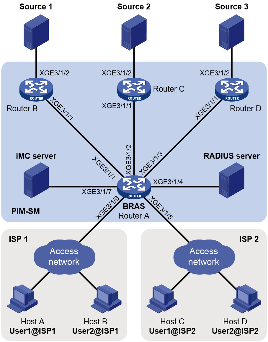
Table 3 Interface and IP address assignment
|
Device |
Interface |
IP address |
Device |
Interface |
IP address |
|
Source 1 |
— |
10.100.1.1/24 |
Host A |
— |
192.168.1.2/24 |
|
Source 2 |
— |
10.100.2.1/24 |
Host B |
— |
192.168.1.3/24 |
|
Source 3 |
— |
10.100.3.1/24 |
Host C |
— |
192.168.2.2/24 |
|
RADIUS server |
— |
11.110.4.2/24 |
Host D |
— |
192.168.2.3/24 |
|
Router B |
XGE3/1/1 |
11.110.1.2/24 |
Router A |
XGE3/1/1 |
11.110.1.1/24 |
|
Router B |
XGE3/1/2 |
10.100.1.2/24 |
Router A |
XGE3/1/2 |
11.110.2.1/24 |
|
Router C |
XGE3/1/1 |
11.110.2.2/24 |
Router A |
XGE3/1/3 |
11.110.3.1/24 |
|
Router C |
XGE3/1/2 |
10.100.2.2/24 |
Router A |
XGE3/1/4 |
11.110.4.1/24 |
|
Router D |
XGE3/1/1 |
11.110.3.2/24 |
Router A |
XGE3/1/5.1 |
192.168.1.1/24 |
|
Router D |
XGE3/1/2 |
10.100.3.2/24 |
Router A |
XGE3/1/5.2 |
192.168.2.1/24 |
Procedure
1. Assign an IP address and subnet mask to each interface, as shown in Table 3. (Details not shown.)
2. Configure OSPF in the PIM-SM domain. (Details not shown.)
3. Enable IP multicast routing, and configure PIM-SM:
# On Router A, enable IP multicast routing.
<RouterA> system-view
[RouterA] multicast routing
[RouterA-mrib] quit
# Enable PIM-SM on Ten-GigabitEthernet 3/1/1 through Ten-GigabitEthernet 3/1/3.
[RouterA] interface ten-gigabitethernet 3/1/1
[RouterA-Ten-GigabitEthernet3/1/1] pim sm
[RouterA-Ten-GigabitEthernet3/1/1] quit
[RouterA] interface ten-gigabitethernet 3/1/2
[RouterA-Ten-GigabitEthernet3/1/2] pim sm
[RouterA-Ten-GigabitEthernet3/1/2] quit
[RouterA] interface ten-gigabitethernet 3/1/3
[RouterA-Ten-GigabitEthernet3/1/3] pim sm
[RouterA-Ten-GigabitEthernet3/1/3] quit
# On Router B, enable IP multicast routing.
<RouterB> system-view
[RouterB] multicast routing
[RouterB-mrib] quit
# Enable PIM-SM on each interface.
[RouterB] interface ten-gigabitethernet 3/1/1
[RouterB-Ten-GigabitEthernet3/1/1] pim sm
[RouterB-Ten-GigabitEthernet3/1/1] quit
[RouterB] interface ten-gigabitethernet 3/1/2
[RouterB-Ten-GigabitEthernet3/1/2] pim sm
[RouterB-Ten-GigabitEthernet3/1/2] quit
# Configure Router C and Router D in the same way Router B is configured. (Details not shown.)
# On Router A, configure Ten-GigabitEthernet 3/1/2 as a C-BSR and a C-RP.
[RouterA] pim
[RouterA-pim] c-bsr 11.110.2.1
[RouterA-pim] c-rp 11.110.2.1
[RouterA-pim] quit
4. Configure the access service on the BRAS:
# Configure a RADIUS scheme.
[RouterA] radius scheme spec
[RouterA-radius-spec] primary authentication 11.110.4.2 key simple 123456
[RouterA-radius-spec] primary accounting 11.110.4.2 key simple 123456
[RouterA-radius-spec] user-name-format without-domain
[RouterA-radius-spec] nas-ip 11.110.4.1
[RouterA-radius-spec] quit
# Create an ISP domain named isp1, and specify the STB service for users in the ISP domain.
[RouterA] domain name isp1
[RouterA-isp-isp1] service-type stb
# Configure AAA methods for ISP domain isp1.
[RouterA-isp-isp1] authentication ipoe radius-scheme spec
[RouterA-isp-isp1] authorization ipoe radius-scheme spec
[RouterA-isp-isp1] accounting ipoe radius-scheme spec
[RouterA-isp-isp1] quit
# Create an ISP domain named isp2, and specify the STB service for users in the ISP domain.
[RouterA] domain name isp2
[RouterA-isp-isp2] service-type stb
# Configure AAA methods for ISP domain isp2.
[RouterA-isp-isp2] authentication ipoe radius-scheme spec
[RouterA-isp-isp2] authorization ipoe radius-scheme spec
[RouterA-isp-isp2] accounting ipoe radius-scheme spec
[RouterA-isp-isp2] quit
# Enable DHCP on Router A.
[RouterA] dhcp enable
# Enable the DHCP server to return a DHCP-NAK message if the client notions of their IP addresses are incorrect.
[RouterA] dhcp server request-ip-address check
# Create an IP pool named 1.
[RouterA] ip pool 1 bas local
# Specify gateway IP address 192.168.2.1 and network mask length 24 in IP pool 1.
[RouterA-ip-pool-1] gateway 192.168.2.1 24
# Exclude IP address 192.168.2.1 from dynamic allocation in IP pool 1.
[RouterA-ip-pool-1] gateway 192.168.2.1 24
# Specify the domain name isp1 in IP pool 1.
[RouterA-ip-pool-1] domain-name isp1
[RouterA-ip-pool-1] quit
# Create an IP pool named 2.
[RouterA] ip pool 2 bas local
# Specify gateway IP address 192.168.3.1 and network mask length 24 in IP pool 2.
[RouterA-ip-pool-2] gateway 192.168.3.1 24
# Exclude IP address 192.168.3.1 from dynamic allocation in IP pool 2.
[RouterA-ip-pool-2] gateway 192.168.2.1 24
# Specify the domain name isp2 in IP pool 2.
[RouterA-ip-pool-2] domain-name isp2
[RouterA-ip-pool-2] quit
# Configure Ten-GigabitEthernet 3/1/5.1 to terminate VLAN-tagged packets whose outer VLAN ID is 1 and inner VLAN ID is in the range of 1 to 100.
[RouterA] interface ten-gigabitethernet 3/1/5.1
[RouterA-Ten-GigabitEthernet3/1/5.1] vlan-type dot1q vid 1 second-dot1q 1 to 100
# Configure the DHCP service on Ten-GigabitEthernet 3/1/5.1.
[RouterA-Ten-GigabitEthernet3/1/5.1] dhcp server apply ip-pool 1
[RouterA-Ten-GigabitEthernet3/1/5.1] ip subscriber routed enable
[RouterA-Ten-GigabitEthernet3/1/5.1] ip subscriber dhcp domain isp1
[RouterA-Ten-GigabitEthernet3/1/5.1] quit
# Configure Ten-GigabitEthernet 3/1/5.2 to terminate VLAN-tagged packets whose outer VLAN ID is 2 and inner VLAN ID is in the range of 1 to 100.
[RouterA] interface ten-gigabitethernet 3/1/5.2
[RouterA-Ten-GigabitEthernet3/1/5.2] vlan-type dot1q vid 2 second-dot1q 1 to 100
# Configure the DHCP service on Ten-GigabitEthernet 3/1/5.2.
[RouterA-Ten-GigabitEthernet3/1/5.2] dhcp server apply ip-pool 2
[RouterA-Ten-GigabitEthernet3/1/5.2] ip subscriber routed enable
[RouterA-Ten-GigabitEthernet3/1/5.2] ip subscriber dhcp domain isp2
[RouterA-Ten-GigabitEthernet3/1/5.2] quit
5. Configure multicast access control on the BRAS:
# Enable IGMP and multicast access control, and enable per-session multicast forwarding on Ten-GigabitEthernet 3/1/5.1.
[RouterA] interface ten-gigabitethernet 3/1/5.1
[RouterA-Ten-GigabitEthernet3/1/5.1] igmp enable
[RouterA-Ten-GigabitEthernet3/1/5.1] igmp authorization-enable
[RouterA-Ten-GigabitEthernet3/1/5.1] igmp join-by-session
[RouterA-Ten-GigabitEthernet3/1/5.1] quit
# Configure Ten-GigabitEthernet 3/1/5.2 in the same way Ten-GigabitEthernet 3/1/5.1 is configured. (Details not shown.)
# Configure an access policy in user profile profile1 to authorize IGMP users to join multicast groups 224.1.1.1 and 225.1.1.1.
[RouterA] acl basic 2000
[RouterA-acl-ipv4-basic-2000] rule permit source 224.1.1.1 0
[RouterA-acl-ipv4-basic-2000] rule permit source 225.1.1.1 0
[RouterA-acl-ipv4-basic-2000] quit
[RouterA] user-profile profile1
[RouterA-user-profile-profile1] igmp access-policy 2000
[RouterA-user-profile-profile1] quit
# Specify user profile profile1 for users in ISP domain isp1.
[RouterA] domain name isp1
[RouterA-isp-isp1] authorization-attribute user-profile profile1
[RouterA-isp-isp1] quit
# Configure an access policy in user profile profile2 to authorize IGMP users to join multicast groups 225.1.1.1 and 226.1.1.1.
[RouterA] acl basic 2001
[RouterA-acl-ipv4-basic-2001] rule permit source 225.1.1.1 0
[RouterA-acl-ipv4-basic-2001] rule permit source 226.1.1.1 0
[RouterA-acl-ipv4-basic-2001] quit
[RouterA] user-profile profile2
[RouterA-user-profile-profile2] igmp access-policy 2001
[RouterA-user-profile-profile2] quit
# Specify user profile profile2 for users in ISP domain isp2.
[RouterA] domain name isp2
[RouterA-isp-isp2] authorization-attribute user-profile profile2
[RouterA-isp-isp2] quit
Verifying the configuration
# Display authorized IGMP user information on Router A after Host A and Host C log in.
[RouterA] display igmp user-info
Authorized users in total: 2
User name: user1@isp1
Access type: IPoE
Interface: Multicast-UA1
Access interface: Ten-GigabitEthernet3/1/5.1
User address: 192.168.1.2
User mac-address: 0010-9400-001b
User ID: 0x30000000 (VLAN ID 1, Second VLAN ID 100)
VLAN ID: 1
Second VLAN ID: 2
Maximum allowed groups: 4
User profile: profile1
Authorized group list:
User name: user1@isp2
Access type: IPoE
Interface: Multicast-UA2
Access interface: Ten-GigabitEthernet3/1/5.2
User address: 192.168.2.2
User mac-address: 0010-9400-002b
User ID: 0x30000000 (VLAN ID 2, Second VLAN ID 100)
VLAN ID: 2
Second VLAN ID: 2
Maximum allowed groups: 4
User profile: profile2
Authorized pgroup rograms list:
Troubleshooting IGMP
No membership information on the receiver-side device
Symptom
When a host sends a report for joining multicast group G, no membership information of multicast group G exists on the device closest to that host.
Solution
To resolve the issue:
1. Use the display igmp interface command to verify that the networking, interface connection, and IP address configuration are correct.
2. Use the display current-configuration command to verify that multicast routing is enabled. If it is not enabled, use the multicast routing command in system view to enable IP multicast routing. In addition, verify that IGMP is enabled on the associated interfaces.
3. Use the display igmp interface command to verify that the IGMP version on the interface is lower than that on the host.
4. Use the display current-configuration interface command to verify that no multicast group policies have been configured to filter IGMP reports for multicast group G.
5. If the issue persists, contact H3C Support.
Inconsistent membership information on the devices on the same subnet
Symptom
Different memberships are maintained on different IGMP devices on the same subnet.
Solution
To resolve the issue:
1. Use the display current-configuration command to verify the IGMP information on the interfaces. Make sure the devices on the subnet have the same IGMP settings on their interfaces.
2. Use the display igmp interface command on all devices on the same subnet to verify the IGMP-related timer settings. Make sure the settings are consistent on all the devices.
3. Use the display igmp interface command to verify that all devices on the same subnet are running the same IGMP version.
4. If the issue persists, contact H3C Support.
