- Table of Contents
-
- 05-Network Connectivity Configuration Guide
- 00-Preface
- 01-About the network connectivity configuration guide
- 02-MAC address table configuration
- 03-Ethernet link aggregation configuration
- 04-Port isolation configuration
- 05-VLAN configuration
- 06-Loop detection configuration
- 07-Spanning tree configuration
- 08-LLDP configuration
- 09-Layer 2 forwarding configuration
- 10-L2TP configuration
- 11-ARP configuration
- 12-IP addressing configuration
- 13-DHCP configuration
- 14-DHCP snooping configuration
- 15-DHCPv6 configuration
- 16-DHCPv6 snooping configuration
- 17-DNS configuration
- 18-HTTP configuration
- 19-HTTP redirect configuration
- 20-IP forwarding basics configuration
- 21-Fast forwarding configuration
- 22-Adjacency table configuration
- 23-IP performance optimization configuration
- 24-IPv6 basics configuration
- 25-IPv6 neighbor discovery configuration
- 26-IPv6 fast forwarding configuration
- 27-IPv6 transition technologies configuration
- 28-NAT configuration
- 29-GRE configuration
- 30-Basic IP routing configuration
- 31-Static routing configuration
- 32-OSPF configuration
- 33-Policy-based routing configuration
- 34-IPv6 static routing configuration
- 35-IPv6 policy-based routing configuration
- 36-Multicast overview
- 37-IGMP snooping configuration
- 38-MLD snooping configuration
- Related Documents
-
| Title | Size | Download |
|---|---|---|
| 27-IPv6 transition technologies configuration | 129.09 KB |
IPv6 transition technologies overview
About IPv6 transition technologies
Configuring IPv6 over IPv4 tunneling
Configuring an IPv6 over IPv4 manual tunnel
Example: Configuring an IPv6 over IPv4 manual tunnel
Verifying and maintaining IPv6 over IPv4 tunneling
Displaying IPv6 over IPv4 tunnel interface information
Clearing IPv6 over IPv4 tunnel interface information
IPv6 transition technologies overview
About IPv6 transition technologies
IPv6 transition technologies enable communication between IPv4 and IPv6 networks.
Dual stack
Dual stack is the most direct transition approach. A network node that supports both IPv4 and IPv6 is a dual-stack node. A dual-stack node configured with an IPv4 address and an IPv6 address can forward both IPv4 and IPv6 packets. An application that supports both IPv4 and IPv6 prefers IPv6 at the network layer.
Dual stack is suitable for communication between IPv4 nodes or between IPv6 nodes. It is the basis of all transition technologies. However, it does not solve the IPv4 address depletion issue because each dual-stack node must have a globally unique IPv4 address.
NAT-PT
Network Address Translation – Protocol Translation (NAT-PT) enables communication between IPv4 and IPv6 nodes by translating between IPv4 and IPv6 packets. It performs IP address translation, and according to different protocols, performs semantic translation for packets. This technology is only suitable for communication between a pure IPv4 node and a pure IPv6 node.
Tunneling
Tunneling uses one network protocol to encapsulate the packets of another network protocol and transfers them over the network. For example, IPv6 over IPv4 tunneling.
IPv6 over IPv4 tunneling
Implementation
IPv6 over IPv4 tunneling enables isolated IPv6 networks to communicate, as shown in Figure 1.
|
|
NOTE: The devices at both ends of an IPv6 over IPv4 tunnel must support the IPv4/IPv6 dual stack. |
Figure 1 IPv6 over IPv4 tunnel
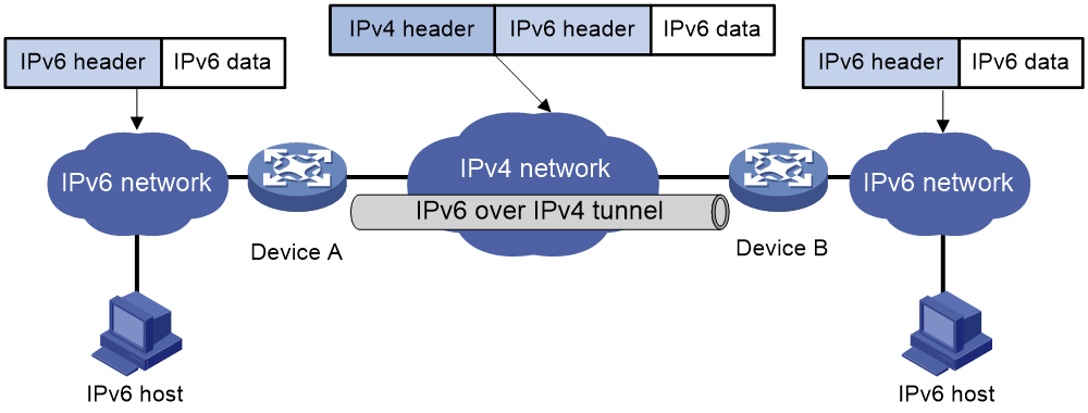
The IPv6 over IPv4 tunnel processes packets by using the following steps:
1. A host in the IPv6 network sends an IPv6 packet to Device A at the tunnel source.
2. After Device A receives the IPv6 packet, it processes the packet as follows:
a. Searches the routing table to identify the outgoing interface for the IPv6 packet.
The outgoing interface is the tunnel interface, so Device A knows that the packet needs to be forwarded through the tunnel.
b. Adds an IPv4 header to the IPv6 packet and forwards the packet through the physical interface of the tunnel.
In the IPv4 header, the source IPv4 address is the IPv4 address of the tunnel source, and the destination IPv4 address is the IPv4 address of the tunnel destination.
3. Upon receiving the packet, Device B de-encapsulates the packet.
4. If the destination address of the IPv6 packet is itself, Device B forwards it to the upper-layer protocol. If it is not, Device B forwards it according to the routing table.
Tunnel modes
IPv6 over IPv4 tunnels include manually configured tunnels and automatic tunnels, depending on how the IPv4 address of the tunnel destination is obtained.
· Manually configured tunnel—The destination IPv4 address of the tunnel cannot be automatically obtained from the destination IPv6 address of an IPv6 packet at the tunnel source. It must be manually configured.
· Automatic tunnel—The destination IPv4 address of the tunnel can be automatically obtained from the destination IPv6 address (with an IPv4 address embedded) of an IPv6 packet at the tunnel source.
The source IPv4 addresses for all IPv6 over IPv4 tunnels are manually configured.
According to the way an IPv6 packet is encapsulated, IPv6 over IPv4 tunnels are divided into the modes shown in the following sections.
IPv6 over IPv4 manual tunneling
An IPv6 over IPv4 manual tunnel is a point-to-point link. To establish a manual tunnel, you must manually configure the source and destination addresses of the tunnel at both ends of the tunnel.
Manual tunneling provides the following solutions:
· Connects isolated IPv6 networks over an IPv4 network.
· Connects an IPv6 network and an IPv4/IPv6 dual-stack host over an IPv4 network.
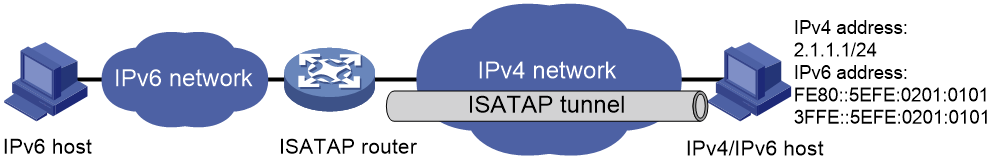
ISATAP tunneling
An ISATAP tunnel is a point-to-multipoint automatic tunnel. It provides a solution to connect an IPv6 host and an IPv6 network over an IPv4 network.
The destination address of an ISATAP tunnel is an ISATAP address. The address format is prefix:0:5EFE:abcd:efgh/64.
· The 64-bit prefix is a valid IPv6 unicast address prefix.
· The abcd:efgh/64 segments represent a 32-bit IPv4 address in hexadecimal notation, which identifies the tunnel destination but does not require global uniqueness.
ISATAP tunnels are mainly used for communication between IPv6 routers or between an IPv6 host and an IPv6 router over an IPv4 network.
Figure 2 Principle of ISATAP tunneling
Configuring IPv6 over IPv4 tunneling
Configuring an IPv6 over IPv4 manual tunnel
Restrictions and guidelines
When you perform tasks in this section, follow these restrictions and guidelines:
· The tunnel destination address specified on the local device must be identical with the tunnel source address specified on the tunnel peer device.
· Do not specify the same tunnel source and destination addresses for the tunnel interfaces in the same mode on a device.
· To ensure correct packet forwarding, identify whether the destination IPv6 network and the IPv6 address of the local tunnel interface are on the same subnet. If they are not, configure a route reaching the destination IPv6 network through the tunnel interface. You can configure the route by using one of the following methods:
¡ Configure a static route, and specify the local tunnel interface as the outgoing interface or specify the IPv6 address of the peer tunnel interface as the next hop.
¡ Enable a dynamic routing protocol on both the local and remote tunnel interfaces.
For more information about route configuration, see Network Connectivity Configuration Guide.
· IPv6 over IPv4 manual tunnel configuration commands include the following common tunnel interface commands:
¡ interface tunnel.
¡ source.
¡ destination.
¡ tunnel dfbit enable.
For more information about these and more tunnel interface commands, see Interface Command Reference.
Procedure
1. Enter system view.
system-view
2. Enter IPv6 over IPv4 manual tunnel interface view.
interface tunnel number [ mode ipv6-ipv4 ]
3. Specify an IPv6 address for the tunnel interface.
See basic IPv6 settings in Network Connectivity Configuration Guide.
4. Configure a source address or source interface for the tunnel interface.
source { ipv4-address | interface-type interface-number }
By default, no source address or source interface is configured for the tunnel interface.
If you specify a source address, it is used as the source IP address of tunneled packets.
If you specify a source interface, the primary IP address of this interface is used as the source IP address of tunneled packets.
5. Configure a destination address for the tunnel interface.
destination ipv4-address
By default, no destination address is configured for the tunnel interface.
The tunnel destination address must be the IP address of the receiving interface on the tunnel peer. It is used as the destination IP address of tunneled packets.
6. (Optional.) Set the DF bit for tunneled packets.
tunnel dfbit enable
By default, the DF bit is not set for tunneled packets.
Example: Configuring an IPv6 over IPv4 manual tunnel
Network configuration
As shown in Figure 3, configure an IPv6 over IPv4 tunnel between Device A and Device B so the two IPv6 networks can reach each other over the IPv4 network. Because the tunnel destination IPv4 address cannot be automatically obtained from the destination IPv6 addresses, configure an IPv6 over IPv4 manual tunnel.
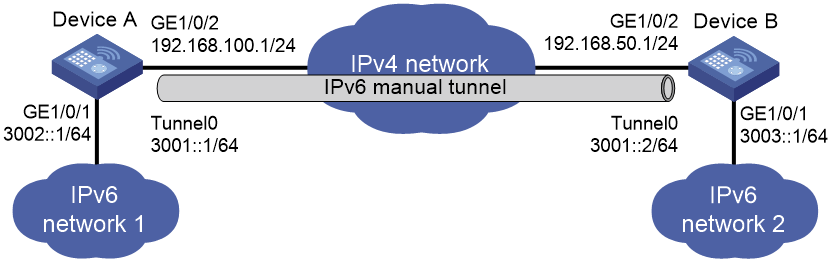
Prerequisites
Make sure Device A and Device B can reach each other through IPv4.
Procedure
1. Configure Device A:
# Assign an IPv4 address to interface GigabitEthernet 1/0/2.
<DeviceA> system-view
[DeviceA] interface gigabitethernet 1/0/2
[DeviceA-GigabitEthernet1/0/2] ip address 192.168.100.1 255.255.255.0
[DeviceA-GigabitEthernet1/0/2] quit
# Assign an IPv6 address to interface GigabitEthernet 1/0/1.
[DeviceA] interface gigabitethernet 1/0/1
[DeviceA-GigabitEthernet1/0/1] ipv6 address 3002::1 64
[DeviceA-GigabitEthernet1/0/1] quit
# Create IPv6 over IPv4 manual tunnel interface Tunnel 0.
[DeviceA] interface tunnel 0 mode ipv6-ipv4
# Specify an IPv6 address for the tunnel interface.
[DeviceA-Tunnel0] ipv6 address 3001::1/64
# Specify GigabitEthernet 1/0/2 as the source interface of the tunnel.
[DeviceA-Tunnel0] source gigabitethernet 1/0/2
# Specify the IP address of GigabitEthernet 1/0/2 on Device B as the destination address of the tunnel.
[DeviceA-Tunnel0] destination 192.168.50.1
[DeviceA-Tunnel0] quit
# Configure a static route destined for IPv6 network 2 through Tunnel 0.
[DeviceA] ipv6 route-static 3003:: 64 tunnel 0
2. Configure Device B:
# Assign an IPv4 address to interface GigabitEthernet 1/0/2.
<DeviceB> system-view
[DeviceB] interface gigabitethernet 1/0/2
[DeviceB-GigabitEthernet1/0/2] ip address 192.168.50.1 255.255.255.0
[DeviceB-GigabitEthernet1/0/2] quit
# Assign an IPv6 address to interface GigabitEthernet 1/0/1.
[DeviceB] interface gigabitethernet 1/0/1
[DeviceB-GigabitEthernet1/0/1] ipv6 address 3003::1 64
[DeviceB-GigabitEthernet1/0/1] quit
# Create IPv6 over IPv4 manual tunnel interface Tunnel 0.
[DeviceB] interface tunnel 0 mode ipv6-ipv4
# Specify an IPv6 address for the tunnel interface.
[DeviceB-Tunnel0] ipv6 address 3001::2/64
# Specify GigabitEthernet 1/0/2 as the source interface of the tunnel.
[DeviceB-Tunnel0] source gigabitethernet 1/0/2
# Specify the IP address of GigabitEthernet 1/0/2 on Device A as the destination address of the tunnel.
[DeviceB-Tunnel0] destination 192.168.100.1
[DeviceB-Tunnel0] quit
# Configure a static route destined for IPv6 network 1 through Tunnel 0.
[DeviceB] ipv6 route-static 3002:: 64 tunnel 0
Verifying the configuration
# Use the display ipv6 interface command to display tunnel interface status on Device A and Device B. Verify that interface Tunnel 0 is up. (Details not shown.)
# Verify that Device A and Device B can ping the IPv6 address of GigabitEthernet 1/0/1 of each other. This example uses Device A.
[DeviceA] ping ipv6 3003::1
Ping6(56 data bytes) 3001::1 --> 3003::1, press CTRL_C to break
56 bytes from 3003::1, icmp_seq=0 hlim=64 time=45.000 ms
56 bytes from 3003::1, icmp_seq=1 hlim=64 time=10.000 ms
56 bytes from 3003::1, icmp_seq=2 hlim=64 time=4.000 ms
56 bytes from 3003::1, icmp_seq=3 hlim=64 time=10.000 ms
56 bytes from 3003::1, icmp_seq=4 hlim=64 time=11.000 ms
--- Ping6 statistics for 3003::1 ---
5 packet(s) transmitted, 5 packet(s) received, 0.0% packet loss
round-trip min/avg/max/std-dev = 4.000/16.000/45.000/14.711 ms
Configuring an ISATAP tunnel
Restrictions and guidelines
Follow these guidelines when you configure an ISATAP tunnel:
· You do not need to configure a destination address for an ISATAP tunnel, because the destination IPv4 address is embedded in the ISATAP address.
· Do not specify the same source addresses for local tunnel interfaces in the same tunnel mode.
· Because automatic tunnels do not support dynamic routing, configure a static route destined for the destination IPv6 network at each tunnel end. You can specify the local tunnel interface as the egress interface of the route or specify the IPv6 address of the peer tunnel interface as the next hop of the route. For more information about route configuration, see IPv6 static routing in Network Connectivity Configuration Guide.
· ISATAP tunnel configuration commands include the following common tunnel interface commands:
¡ interface tunnel.
¡ source.
¡ tunnel dfbit enable.
For more information about these and more tunnel interface commands, see Interface Command Reference.
Procedure
1. Enter system view.
system-view
2. Enter ISATAP tunnel interface view.
interface tunnel number [ mode ipv6-ipv4 isatap ]
3. Specify an IPv6 address for the tunnel interface.
See "Configuring basic IPv6 settings."
4. Configure a source address or source interface for the tunnel interface.
source { ipv4-address | interface-type interface-number }
By default, no source address or source interface is configured for the tunnel interface.
If you specify a source address, it is used as the source IP address of tunneled packets.
If you specify a source interface, the primary IP address of this interface is used as the source IP address of tunneled packets.
5. (Optional.) Set the DF bit for tunneled packets.
tunnel dfbit enable
By default, the DF bit is not set for tunneled packets.
Verifying and maintaining IPv6 over IPv4 tunneling
Displaying IPv6 over IPv4 tunnel interface information
Perform display tasks in any view.
· Display IPv6 over IPv4 tunnel interface information.
display tunnel-interface [ number ]
For more information about this command, see tunnel interface commands in Interface Command Reference.
· Display information about IPv6 over IPv4 tunnel interfaces.
display interface [ tunnel [ number ] ] [ brief [ description | down ] ]
For more information about this command, see tunnel interface commands in Interface Command Reference.
· Display IPv6 information about IPv6 over IPv4 tunnel interfaces.
display ipv6 interface [ tunnel [ number ] ] [ brief ]
For more information about this command, see IPv6 basics in Network Connectivity Command Reference.
Clearing IPv6 over IPv4 tunnel interface information
Perform clear tasks in user view.
· Clear IPv6 over IPv4 tunnel interface statistics.
reset counters interface [ tunnel [ number ] ]
For more information about this command, see common interface commands in Interface Command Reference.
· Clear IPv6 statistics on IPv6 over IPv4 tunnel interfaces.
reset ipv6 statistics [ slot slot-number ]
For more information about this command, see IPv6 basics in Layer 3—IP Services Command Reference.
