- Table of Contents
-
- 05-Network Connectivity Configuration Guide
- 00-Preface
- 01-About the network connectivity configuration guide
- 02-MAC address table configuration
- 03-Ethernet link aggregation configuration
- 04-Port isolation configuration
- 05-VLAN configuration
- 06-Loop detection configuration
- 07-Spanning tree configuration
- 08-LLDP configuration
- 09-Layer 2 forwarding configuration
- 10-L2TP configuration
- 11-ARP configuration
- 12-IP addressing configuration
- 13-DHCP configuration
- 14-DHCP snooping configuration
- 15-DHCPv6 configuration
- 16-DHCPv6 snooping configuration
- 17-DNS configuration
- 18-HTTP configuration
- 19-HTTP redirect configuration
- 20-IP forwarding basics configuration
- 21-Fast forwarding configuration
- 22-Adjacency table configuration
- 23-IP performance optimization configuration
- 24-IPv6 basics configuration
- 25-IPv6 neighbor discovery configuration
- 26-IPv6 fast forwarding configuration
- 27-IPv6 transition technologies configuration
- 28-NAT configuration
- 29-GRE configuration
- 30-Basic IP routing configuration
- 31-Static routing configuration
- 32-OSPF configuration
- 33-Policy-based routing configuration
- 34-IPv6 static routing configuration
- 35-IPv6 policy-based routing configuration
- 36-Multicast overview
- 37-IGMP snooping configuration
- 38-MLD snooping configuration
- Related Documents
-
| Title | Size | Download |
|---|---|---|
| 03-Ethernet link aggregation configuration | 332.29 KB |
Contents
Configuring Ethernet link aggregation
About Ethernet link aggregation
Ethernet link aggregation application scenario
Aggregate interface, aggregation group, and member port
How static link aggregation works
How dynamic link aggregation works
Load sharing modes for link aggregation groups
Restrictions and guidelines: Mixed use of manual and automatic link aggregation configuration
Ethernet link aggregation tasks at a glance
Configuring a manual link aggregation
Configuring a Layer 2 aggregation group
Configuring an aggregate interface
Configuring the basic parameters of an aggregate interface
Configuring jumbo frame support
Configuring an edge aggregate interface
Restoring the default settings for an aggregate interface
Setting the minimum and maximum numbers of Selected ports for an aggregation group
Setting the minimum percentage of Selected ports in an aggregation group
Enabling the preemption feature on an aggregate interface
Configuring load sharing for link aggregation groups
Setting static load sharing modes for link aggregation groups
Configuring link aggregation load sharing algorithm settings
Isolating aggregate interfaces on the device
Verifying and maintaining Ethernet link aggregation
Verifying aggregate interface and aggregation member port running status
Displaying the local system ID
Displaying link-aggregation load sharing information
Displaying and clearing interface statistics
Clearing LACP statistics for link aggregation member ports
Ethernet link aggregation configuration examples
Example: Configuring a Layer 2 static aggregation group
Configuring Ethernet link aggregation
About Ethernet link aggregation
Ethernet link aggregation bundles multiple physical Ethernet links into one logical link (called an aggregate link). Link aggregation provides the following benefits:
· Increased bandwidth beyond the limits of a single individual link. In an aggregate link, traffic is distributed across the member ports.
· Improved link reliability. The member ports dynamically back up one another. When a member port fails, its traffic is automatically switched to other member ports.
Ethernet link aggregation application scenario
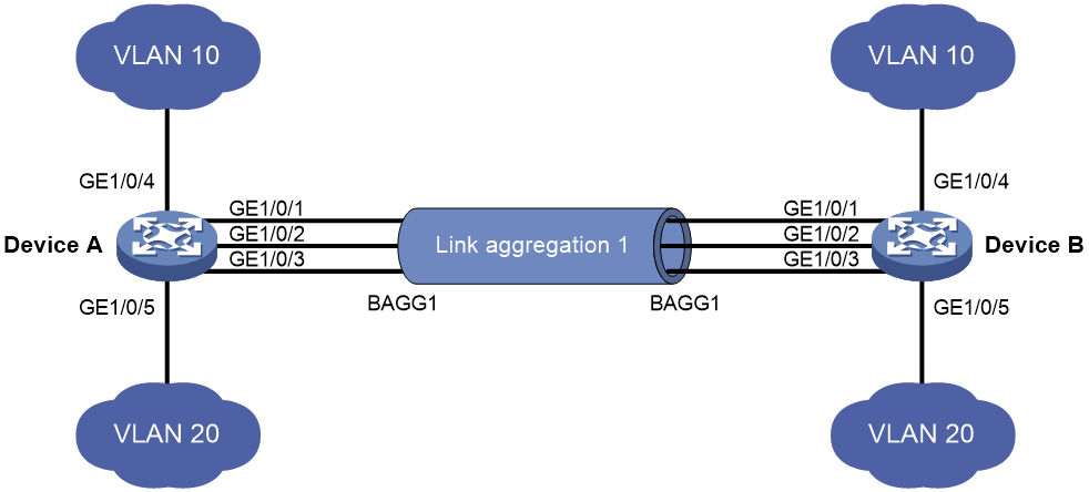
As shown in Figure 1, Device A and Device B are connected by three physical Ethernet links. These physical Ethernet links are combined into an aggregate link called link aggregation 1. The bandwidth of this aggregate link can reach up to the total bandwidth of the three physical Ethernet links. At the same time, the three Ethernet links back up one another. When a physical Ethernet link fails, the traffic transmitted on the failed link is switched to the other two links.
Figure 1 Ethernet link aggregation diagram

Aggregate interface, aggregation group, and member port
Each link aggregation is represented by a logical aggregate interface. Each aggregate interface has an automatically created aggregation group, which contains member ports to be used for aggregation. The type and number of an aggregation group are the same as its aggregate interface.
Supported aggregate interface types
An aggregate interface can be one of the following types:
· Layer 2—A Layer 2 aggregate interface is created manually. The member ports in a Layer 2 aggregation group can only be Layer 2 Ethernet interfaces.
The port rate of an aggregate interface equals the total rate of its Selected member ports. Its duplex mode is the same as that of the Selected member ports. For more information about Selected member ports, see "Aggregation states of member ports in an aggregation group."
Aggregation states of member ports in an aggregation group
A member port in an aggregation group can be in any of the following aggregation states:
· Selected—A Selected port can forward traffic.
· Unselected—An Unselected port cannot forward traffic.
· Individual—An Individual port can forward traffic as a normal physical port. This state is peculiar to the member ports of edge aggregate interfaces. A member port is placed in Individual state if it has not received LACPDUs before the first expiration of the LACP timeout timer after either of the following event occurs:
¡ The aggregate interface is configured as an edge aggregate interface.
¡ The member port goes down and then comes up after it is placed in Unselected or Selected state.
For more information about edge aggregate interfaces, see "Edge aggregate interface."
Operational key
When aggregating ports, the system automatically assigns each port an operational key based on port information, such as port rate and duplex mode. Any change to this information triggers a recalculation of the operational key.
In an aggregation group, all Selected ports have the same operational key.
Configuration types
Port configuration includes the attribute configuration and protocol configuration. Attribute configuration affects the aggregation state of the port but the protocol configuration does not.
Attribute configuration
To become a Selected port, a member port must have the same attribute configuration as the aggregate interface. Table 1 describes the attribute configuration.
Table 1 Attribute configuration
|
Feature |
Attribute configuration |
|
VLAN |
VLAN attribute settings: · Permitted VLAN IDs. · PVID. · Link type (trunk, hybrid, or access). · PVLAN port type (promiscuous, trunk promiscuous, host, or trunk secondary). · IP subnet-based VLAN configuration. · Protocol-based VLAN configuration. · VLAN tagging mode. For information about VLANs, see "Configuring VLANs." |
Protocol configuration
Protocol configuration of a member port does not affect the aggregation state of the member port. MAC address learning and spanning tree settings are examples of the protocol configuration.
Link aggregation modes
An aggregation group operates in one of the following modes:
· Static—Static aggregation is stable. An aggregation group in static mode is called a static aggregation group. The aggregation states of the member ports in a static aggregation group are not affected by the peer ports.
· Dynamic—An aggregation group in dynamic mode is called a dynamic aggregation group. Dynamic aggregation is implemented through IEEE 802.3ad Link Aggregation Control Protocol (LACP). The local system and the peer system automatically maintain the aggregation states of the member ports. Dynamic link aggregation reduces the administrators' workload.
How static link aggregation works
Reference port selection process
When setting the aggregation states of the ports in an aggregation group, the system automatically chooses a member port as the reference port. A Selected port must have the same operational key and attribute configurations as the reference port.
The system chooses a reference port from the member ports in up state.
The candidate reference ports are organized into different priority levels following these rules:
1. In descending order of port priority.
2. Full duplex.
3. In descending order of speed.
4. Half duplex.
5. In descending order of speed.
From the candidate ports with the same attribute configurations as the aggregate interface, the one with the highest priority level is chosen as the reference port.
· If multiple ports have the same priority level, the port that has been Selected (if any) is chosen. If multiple ports with the same priority level have been Selected, the one with the smallest port number is chosen.
· If multiple ports have the same priority level and none of them has been Selected, the port with the smallest port number is chosen.
Setting the aggregation state of each member port
After the reference port is chosen, the system sets the aggregation state of each member port in the static aggregation group.
Figure 2 Setting the aggregation state of a member port in a static aggregation group
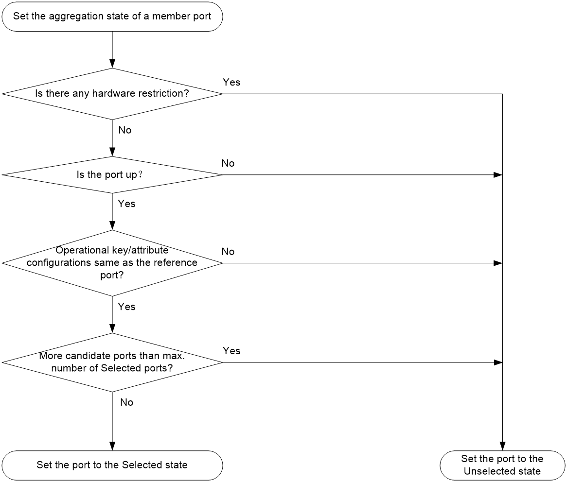
After the limit on Selected ports is reached, the aggregation state of a new member port varies by following conditions:
· The port is placed in Unselected state if the port and the Selected ports have the same port priority. This mechanism prevents traffic interruption on the existing Selected ports. A device reboot can cause the device to recalculate the aggregation states of member ports.
· The port is placed in Selected state when the following conditions are met:
¡ The port and the Selected ports have different port priorities, and the port has a higher port priority than a minimum of one Selected port.
¡ The port has the same attribute configurations as the aggregate interface.
Any operational key or attribute configuration change might affect the aggregation states of link aggregation member ports.
Dynamic link aggregation
About LACP
Dynamic aggregation is implemented through IEEE 802.3ad Link Aggregation Control Protocol (LACP).
LACP uses LACPDUs to exchange aggregation information between LACP-enabled devices. Each member port in a dynamic aggregation group can exchange information with its peer. When a member port receives an LACPDU, it compares the received information with information received on the other member ports. In this way, the two systems reach an agreement on which ports are placed in Selected state.
LACP functions
LACP offers basic LACP functions and extended LACP functions, as described in Table 2.
Table 2 Basic and extended LACP functions
|
Category |
Description |
|
Basic LACP functions |
Implemented through the basic LACPDU fields, including the LACP system priority, system MAC address, port priority, port number, and operational key. |
|
Extended LACP functions |
Implemented by extending the LACPDU with new TLV fields. · If a device supports both extended LACP and cloud cluster, it can participate in LACP MAD as either a cloud cluster member device or an intermediate device. · If a device supports extended LACP but not cloud cluster, it can participate in LACP MAD only as an intermediate device. |
LACP operating modes
LACP can operate in active or passive mode.
When LACP is operating in passive mode on a local member port and its peer port, both ports cannot send LACPDUs. When LACP is operating in active mode on either end of a link, both ports can send LACPDUs.
LACP priorities
LACP priorities include LACP system priority and port priority, as described in Table 3. The smaller the priority value, the higher the priority.
|
Type |
Description |
|
LACP system priority |
Used by two peer devices (or systems) to determine which one is superior in link aggregation. In dynamic link aggregation, the system that has higher LACP system priority sets the Selected state of member ports on its side. The system that has lower priority sets the aggregation state of local member ports the same as their respective peer ports. |
|
Port priority |
Determines the likelihood of a member port to be a Selected port on a system. A port with a higher port priority is more likely to become Selected. |
LACP timeout interval
The LACP timeout interval specifies how long a member port waits to receive LACPDUs from the peer port. If a local member port has not received LACPDUs from the peer within the LACP timeout interval, the member port considers the peer as failed.
The LACP timeout interval also determines the LACPDU sending rate of the peer. LACP timeout intervals include the following types:
· Short timeout interval—3 seconds. If you use the short timeout interval, the peer sends one LACPDU per second.
· Long timeout interval—90 seconds. If you use the long timeout interval, the peer sends one LACPDU every 30 seconds.
Methods to assign interfaces to a dynamic link aggregation group
You can use one of the following methods to assign interfaces to a dynamic link aggregation group:
· Manual assignment—Manually assign interfaces to the dynamic link aggregation group.
· Automatic assignment—Enable automatic assignment on interfaces to have them automatically join a dynamic link aggregation group depending on the peer information in the received LACPDUs.
|
|
NOTE: When you use automatic assignment on one end, you must use manual assignment on the other end. |
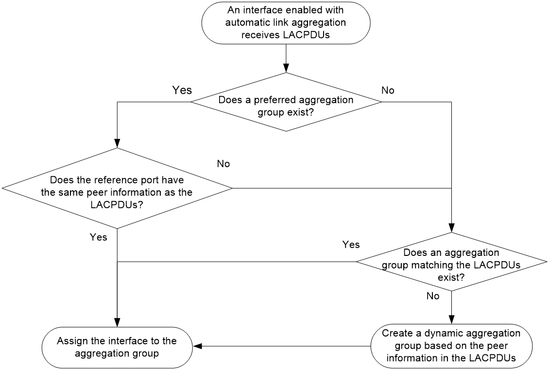
Automatic member port assignment
This feature automates the assignment of aggregation member ports to an aggregation group. You can use this feature when setting up an aggregate link to a server.
As shown in Figure 3, an interface enabled with automatic assignment joins a dynamic aggregation group based on the peer information in the LACPDUs received from the aggregation peer. If none of the existing dynamic aggregation groups is qualified, the device automatically creates a new dynamic aggregation group, Then, the device assigns the interface to that group and synchronizes the interface's attribute configurations to the aggregate interface.
A dynamic aggregation group that contains automatically assigned member ports selects a reference port and Selected ports as described in "How dynamic link aggregation works." The assignment methods of member ports do not change the processes of reference port selection and Selected port selection.
Figure 3 Automatic member port assignment process
How dynamic link aggregation works
Choosing a reference port
The system chooses a reference port from the member ports in up state. A Selected port must have the same operational key and attribute configurations as the reference port.
The local system (the actor) and the peer system (the partner) negotiate a reference port by using the following workflow:
1. The two systems determine the system with the smaller system ID.
A system ID contains the LACP system priority and the system MAC address.
a. The two systems compare their LACP priority values.
The lower the LACP priority, the smaller the system ID. If the LACP priority values are the same, the two systems proceed to step b.
b. The two systems compare their MAC addresses.
The lower the MAC address, the smaller the system ID.
2. The system with the smaller system ID chooses the port with the smallest port ID as the reference port.
A port ID contains a port priority and a port number. The lower the port priority, the smaller the port ID.
a. The system chooses the port with the lowest priority value as the reference port.
If the ports have the same priority, the system proceeds to step b.
b. The system compares their port numbers.
The smaller the port number, the smaller the port ID.
The port with the smallest port number and the same attribute configurations as the aggregate interface is chosen as the reference port.
|
|
NOTE: To identify the port numbers of aggregation member ports, execute the display link-aggregation verbose command and examine the Index field in the command output. |
Setting the aggregation state of each member port
After the reference port is chosen, the system with the smaller system ID sets the state of each member port on its side.
Figure 4 Setting the state of a member port in a dynamic aggregation group
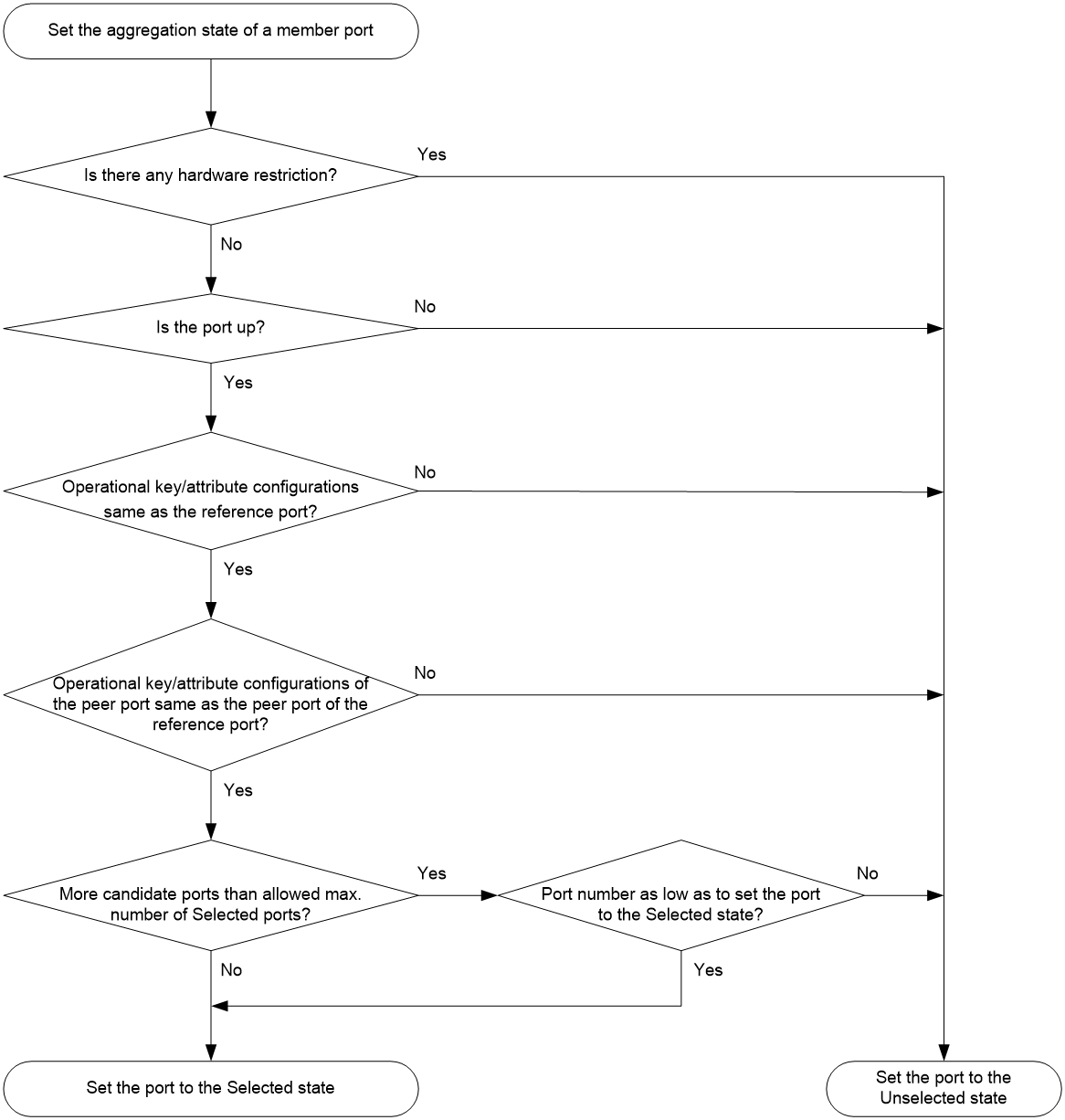
The system with the greater system ID can detect the aggregation state changes on the peer system. The system with the greater system ID sets the aggregation state of local member ports the same as their peer ports.
When you aggregate interfaces in dynamic mode, follow these guidelines:
· A dynamic link aggregation group chooses only full-duplex ports as the Selected ports.
· For stable aggregation and service continuity, do not change the operational key or attribute configurations on any member port.
· When a member port changes to the Selected or Unselected state, its peer port changes to the same aggregation state.
· After the Selected port limit is reached, a newly joining port becomes a Selected port if it is more eligible than a current Selected port.
Edge aggregate interface
Dynamic link aggregation fails on a server-facing aggregate interface if dynamic link aggregation is configured only on the device. The device forwards traffic by using only one of the physical ports that are connected to the server.
To improve link reliability, configure the aggregate interface as an edge aggregate interface. This feature enables all member ports of the aggregation group to forward traffic. When a member port fails, its traffic is automatically switched to other member ports.
After dynamic link aggregation is configured on the server, the device can receive LACPDUs from the server. Then, link aggregation between the device and the server operates correctly.
An edge aggregate interface takes effect only when it is configured on an aggregate interface corresponding to a dynamic aggregation group.
Load sharing modes for link aggregation groups
In a link aggregation group, traffic can be load shared across the Selected ports based on any of the following modes:
· Per-flow load sharing—Distributes traffic on a per-flow basis. The load sharing mode classifies packets into flows and forwards packets of the same flow on the same link. This mode can be one of or a combination of the following hashing keys:
¡ Source or destination IP.
¡ Source or destination MAC.
¡ Source or destination port number.
Restrictions and guidelines: Mixed use of manual and automatic link aggregation configuration
To avoid unexpected aggregation issues, do not use manual assignment, automatic assignment, and automatic link aggregation in any combination. If you use any two of these features in combination, an automatically assigned member port might move between aggregation groups or undesirably change from Selected to Unselected in some situations.
Ethernet link aggregation tasks at a glance
To configure Ethernet link aggregation, perform the following tasks:
2. Configuring link aggregations
¡ Configuring a manual link aggregation
3. (Optional.) Configuring an aggregate interface
¡ Configuring the basic parameters of an aggregate interface
¡ Configuring jumbo frame support
¡ Configuring an edge aggregate interface
An edge aggregate interface uses all member ports to forward traffic when the aggregation peer is not enabled with dynamic link aggregation.
¡ Restoring the default settings for an aggregate interface
4. (Optional.) Adjusting aggregation states of link aggregation member ports
¡ Setting the minimum and maximum numbers of Selected ports for an aggregation group
¡ Setting the minimum percentage of Selected ports in an aggregation group
¡ (Optional.) Configuring load sharing for link aggregation groups
¡ Setting static load sharing modes for link aggregation groups
¡ Configuring link aggregation load sharing algorithm settings
¡ Enabling the preemption feature on an aggregate interface
5. (Optional.) Optimizing traffic forwarding
¡ Isolating aggregate interfaces on the device
Configuring the system ID
About this task
The two ends of a dynamic aggregate link choose a reference port from the end with a smaller system ID.
The system ID contains the LACP system priority and LACP system MAC address. Two devices use the following rules to compare their system IDs:
· If their system IDs contain different LACP system priorities, the system ID with a smaller LACP system priority value is smaller.
· If their system IDs contain the same LACP system priority, the system ID with a lower LACP system MAC address is smaller.
To view the LACP system MAC address and LACP system priority, execute the display link-aggregation verbose command.
You can configure the system ID globally and in aggregate interface view. The global system ID takes effect on all aggregation groups, and an aggregate-interface-specific system ID takes precedence over the global system ID.
Restrictions and guidelines
For member ports to be selected correctly, do not modify the LACP system priority and LACP system MAC address after a dynamic link aggregation is established.
Procedure
1. Enter system view.
system-view
2. Set the LACP system MAC address globally.
lacp system-mac mac-address
By default, the LACP system MAC address is the bridge MAC address of the device.
3. Set the LACP system priority globally.
lacp system-priority priority
By default, the LACP system priority is 32768.
4. Enter aggregate interface view.
¡ Enter Layer 2 aggregate interface view.
interface bridge-aggregation interface-number
5. Set the LACP system MAC address on the aggregate interface.
port lacp system-mac mac-address
By default, the LACP system MAC address is the bridge MAC address of the device.
6. Set the LACP system priority on the aggregate interface.
port lacp system-priority priority
By default, the LACP system priority is 32768.
Configuring a manual link aggregation
Configuring a Layer 2 aggregation group
Configuring a Layer 2 static aggregation group
1. Enter system view.
system-view
2. Create a Layer 2 aggregate interface and enter Layer 2 aggregate interface view.
interface bridge-aggregation interface-number
When you create a Layer 2 aggregate interface, the system automatically creates a Layer 2 static aggregation group numbered the same as that interface.
3. Configure the aggregation group to operate in static mode.
link-aggregation mode static
By default, an aggregation group operates in static mode.
4. Return to system view.
quit
5. Assign an interface to the Layer 2 aggregation group:
a. Enter Layer 2 Ethernet interface view.
interface interface-type interface-number
b. Assign the interface to the Layer 2 aggregation group.
port link-aggregation group group-id [ force ]
Repeat the substeps to assign more interfaces to the aggregation group.
To synchronize the attribute configurations from the aggregate interface when the current interface joins the aggregation group, specify the force keyword.
6. (Optional.) Set the port priority of the interface.
link-aggregation port-priority priority
The default port priority of an interface is 32768.
Configuring a Layer 2 dynamic aggregation group
1. Enter system view.
system-view
2. Create a Layer 2 aggregate interface and enter Layer 2 aggregate interface view.
interface bridge-aggregation interface-number
When you create a Layer 2 aggregate interface, the system automatically creates a Layer 2 static aggregation group numbered the same as that interface.
3. Configure the aggregation group to operate in dynamic mode.
link-aggregation mode dynamic
By default, an aggregation group operates in static mode.
4. Return to system view.
quit
5. Assign an interface to the Layer 2 aggregation group:
a. Enter Layer 2 Ethernet interface view.
interface interface-type interface-number
b. Assign the interface to the Layer 2 aggregation group or enable automatic assignment on that interface.
port link-aggregation group { group-id [ force ] | auto [ group-id ] }
Repeat these two substeps to assign more Layer 2 Ethernet interfaces to the aggregation group.
To synchronize the attribute configurations from the aggregate interface when the current interface joins the aggregation group, specify the force keyword.
To enable automatic assignment, specify the auto keyword. As a best practice, do not modify the configuration on an automatically created aggregate interface or its member ports.
6. Set the LACP operating mode for the interface.
¡ Set the LACP operating mode to passive.
lacp mode passive
¡ Set the LACP operating mode to active.
undo lacp mode
By default, LACP is operating in active mode.
7. (Optional.) Set the port priority for the interface.
link-aggregation port-priority priority
The default setting is 32768.
8. (Optional.) Set the short LACP timeout interval (3 seconds) for the interface.
lacp period short
By default, the long LACP timeout interval (90 seconds) is used by the interface.
Configuring an aggregate interface
Most settings that can be made on Layer 2 Ethernet interfaces can also be made on Layer 2 aggregate interfaces.
Configuring the basic parameters of an aggregate interface
About this task
Shutting down or bringing up an aggregate interface changes the aggregation states of the member ports in the aggregation group of the aggregate interface.
· When you shut down the aggregate interface, all Selected ports become Unselected, and all aggregation member ports become down.
· When you bring up the aggregate interface, the system recalculates the aggregation states of all aggregation member ports.
For more information about the description, bandwidth, and shutdown commands, see common interface commands in Interface Command Reference.
Procedure
1. Enter system view.
system-view
2. Enter aggregate interface view.
¡ Enter Layer 2 aggregate interface view.
interface bridge-aggregation interface-number
3. Configure the interface description.
description text
By default, the description of an interface is interface-name Interface.
You can configure the description of an aggregate interface for administration purposes, for example, describing the purpose of the interface.
4. Set the expected bandwidth for the interface.
bandwidth bandwidth-value
By default, the expected bandwidth (in kbps) is not configured.
The expected bandwidth is an informational parameter used only by higher-layer protocols for calculation. You cannot adjust the actual bandwidth of an interface by using this command.
5. Shut down the interface.
shutdown
By default, an interface is not manually shut down.
|
|
CAUTION: The shutdown command will disconnect all links established on an interface. Make sure you are fully aware of the impacts of this command when you use it on a live network. |
Configuring jumbo frame support
About this task
An aggregate interface might receive frames larger than 1700 bytes during high-throughput data exchanges, such as file transfers. These frames are called jumbo frames.
How an aggregate interface processes jumbo frames depends on whether jumbo frame support is enabled on the interface.
· If configured to deny jumbo frames, the aggregate interface discards jumbo frames.
· If enabled with jumbo frame support, the aggregate interface performs the following operations:
¡ Processes jumbo frames that are within the allowed length.
¡ Discards jumbo frames that exceed the allowed length.
Procedure
1. Enter system view.
system-view
2. Enter aggregate interface view.
¡ Enter Layer 2 aggregate interface view.
interface bridge-aggregation interface-number
3. Allow jumbo frames.
jumboframe enable [ size ]
By default, an aggregate interface allows jumbo frames that are within 4000 bytes to pass through.
If you execute this command multiple times, the most recent configuration takes effect.
Configuring an edge aggregate interface
Restrictions and guidelines
This configuration takes effect only on aggregate interfaces in dynamic mode.
Procedure
1. Enter system view.
system-view
2. Enter aggregate interface view.
¡ Enter Layer 2 aggregate interface view.
interface bridge-aggregation interface-number
3. Configure the aggregate interface as an edge aggregate interface.
lacp edge-port
By default, an aggregate interface does not operate as an edge aggregate interface.
Restoring the default settings for an aggregate interface
Restrictions and guidelines
|
|
CAUTION: The default command might interrupt ongoing network services. Make sure you are fully aware of the impacts of this command when you execute it on a live network. |
The default command might fail to restore the default settings for some commands for reasons such as command dependencies and system restrictions.
To resolve this issue:
1. Use the display this command in interface view to identify these commands.
2. Use their undo forms or follow the command reference to restore their default settings.
3. If the restoration attempt still fails, follow the error message instructions to resolve the issue.
For more information about the default command, see common interface commands in Interface Command Reference.
Procedure
1. Enter system view.
system-view
2. Enter aggregate interface view.
¡ Enter Layer 2 aggregate interface view.
interface bridge-aggregation interface-number
3. Restore the default settings for the aggregate interface.
default
Setting the minimum and maximum numbers of Selected ports for an aggregation group
About this task
The bandwidth of an aggregate link increases as the number of Selected member ports increases. To avoid congestion, you can set the minimum number of Selected ports required for bringing up an aggregate interface.
This minimum threshold setting affects the aggregation states of aggregation member ports and the state of the aggregate interface.
· When the number of member ports eligible to be Selected ports is smaller than the minimum threshold, the following events occur:
¡ The eligible member ports are placed in Unselected state.
¡ The link layer state of the aggregate interface becomes down.
· When the number of member ports eligible to be Selected ports reaches or exceeds the minimum threshold, the following events occur:
¡ The eligible member ports are placed in Selected state.
¡ The link layer state of the aggregate interface becomes up.
The maximum number of Selected ports allowed in an aggregation group is limited by either manual configuration or hardware limitation, whichever value is smaller.
You can implement backup between two ports by performing the following tasks:
· Assigning two ports to an aggregation group.
· Setting the maximum number of Selected ports to 1 for the aggregation group.
Then, only one Selected port is allowed in the aggregation group, and the Unselected port acts as a backup port.
Restrictions and guidelines
For an aggregation group, the maximum number of Selected ports must be equal to or higher than the minimum number of Selected ports.
Procedure
1. Enter system view.
system-view
2. Enter aggregate interface view.
¡ Enter Layer 2 aggregate interface view.
interface bridge-aggregation interface-number
3. Set the minimum number of Selected ports for the aggregation group.
link-aggregation selected-port minimum min-number
By default, the minimum number of Selected ports is not specified for an aggregation group.
4. Set the maximum number of Selected ports for the aggregation group.
link-aggregation selected-port maximum max-number [ lacp-sync ]
By default, the maximum number of Selected ports for an aggregation group is the hardware limitation.
For a static aggregate link, you must set the maximum number of Selected ports to the same value at its two ends.
For a dynamic aggregate link, you must set the maximum number of Selected ports to the same value at its two ends if you do not specify the lacp-sync keyword. If you specify this keyword, the two ends of the aggregate link compare their maximum Selected port number settings and use the smaller value.
Setting the minimum percentage of Selected ports in an aggregation group
About this task
The minimum number of Selected ports in an aggregation group equals the higher one of the following values:
· The number of member ports in the aggregation group multiplied by the minimum percentage of Selected ports.
· The limit set by using the link-aggregation selected-port minimum command.
Restrictions and guidelines
After you perform this task, aggregate interface flapping might occur when ports join or leave an aggregation group. Make sure you are fully aware of the impacts of this command when you execute it on a live network.
If you set the minimum percentage of Selected ports for the aggregation group, do not set the maximum number of Selected ports. If you set the maximum number of Selected ports, the calculated minimum number of Selected ports might be larger than the maximum number of Selected ports.
You must set the same minimum percentage of Selected ports at the two ends of an aggregate link.
Procedure
1. Enter system view.
system-view
2. Enter aggregate interface view.
¡ Enter Layer 2 aggregate interface view.
interface bridge-aggregation interface-number
3. Set the minimum percentage of Selected ports.
link-aggregation selected-port minimum percentage number
By default, the minimum percentage of Selected ports is not set for an aggregation group.
Disabling the default action of selecting a Selected port for dynamic aggregation groups that have not received LACPDUs
About this task
The default port selection action applies to dynamic aggregation groups.
This action automatically chooses the port with the lowest ID from among all up member ports as a Selected port if none of them has received LACPDUs before the LACP timeout interval expires.
After this action is disabled, a dynamic aggregation group will not have any Selected ports to forward traffic if it has not received LACPDUs before the LACP timeout interval expires.
Procedure
1. Enter system view.
system-view
2. Disable the default port selection action.
lacp default-selected-port disable
By default, the default port selection action is enabled for dynamic aggregation groups.
Configuring a dynamic aggregation group to use port speed as the prioritized criterion for reference port selection
About this task
Perform this task to ensure that a dynamic aggregation group selects a high-speed member port as the reference port. After you perform this task, the reference port will be selected based on the criteria in order of device ID, port speed, and port ID.
Restrictions and guidelines
Changing reference port selection criteria might cause transient traffic interruption. Make sure you understand the impact of this task on your network.
You must perform this task at both ends of the aggregate link so the peer aggregation systems use the same criteria for reference port selection.
As a best practice, shut down the peer aggregate interfaces before you execute this command and bring up the interfaces after this command is executed on both of them.
Procedure
1. Enter system view.
system-view
2. Enter aggregate interface view.
¡ Enter Layer 2 aggregate interface view.
interface bridge-aggregation interface-number
3. Specify port speed as the prioritized criterion for reference port selection.
lacp select speed
By default, port ID is the prioritized criterion for reference port selection of a dynamic aggregation group.
Enabling the preemption feature on an aggregate interface
About this task
For a dynamic aggregate interface, when Selected port A fails, the device selects member port B with the highest priority from the member ports that meet the conditions of becoming a Selected port. If the preemption feature is enabled on the aggregate interface, port A will replace port B on recovery. If the preemption feature is disabled on the aggregate interface, port B will continue to be the Selected port to reduce packet loss caused by selected port switching, even if its priority is lower than port A's.
To avoid packet loss caused by an unstable port A taking over port B, set a preemption delay time for the aggregate interface.
Procedure
1. Enter system view.
system-view
2. Enter aggregate interface view.
¡ Enter Layer 2 aggregate interface view.
interface bridge-aggregation interface-number
3. Enable the preemption feature on the aggregate interface.
lacp preempt enable
By default, the preemption feature on an aggregate interface is enabled.
4. Configure the preemption delay time of the aggregate interface.
lacp preempt delay delay-time
By default, the preemption delay for an aggregate interface is 0 seconds, which means preemption occurs immediately.
Configuring load sharing for link aggregation groups
Setting static load sharing modes for link aggregation groups
About this task
You can set the global or group-specific load sharing mode. A link aggregation group preferentially uses the group-specific load sharing mode. If the group-specific load sharing mode is not available, the group uses the global load sharing mode.
Setting the global link-aggregation load sharing mode
1. Enter system view.
system-view
2. Set the global link-aggregation load sharing mode.
link-aggregation global load-sharing mode { destination-ip | destination-mac | destination-port | source-ip | source-mac | source-port }
By default, the device distributes traffic based on the source and destination MAC addresses, and source and destination IP addresses on aggregate links.
Setting the group-specific load sharing mode
1. Enter system view.
system-view
2. Enter aggregate interface view.
¡ Enter Layer 2 aggregate interface view.
interface bridge-aggregation interface-number
3. Set the load sharing mode for the aggregation group.
link-aggregation load-sharing mode { destination-ip | destination-mac | source-ip | source-mac } *
By default, the group-specific load sharing mode is the same as the global load sharing mode.
Configuring link aggregation load sharing algorithm settings
About this task
To optimize traffic distribution on aggregate links, you can configure the link aggregation load sharing algorithm and the hash seed. The algorithm determines the CRC calculation method. The hash seed is a parameter used in hashing.
In default load sharing mode, if the device fails to load share traffic flows across all Selected ports, repeat the following procedure until the problem is resolved:
1. Configure the load sharing algorithm or hash seed.
2. Use the display counters command to view traffic statistics on Selected ports.
You can use a load sharing algorithm and a hash seed individually or in combination to obtain the optimal load sharing performance.
Restrictions and guidelines
This feature does not take effect on per-flow load sharing.
Procedure
1. Enter system view.
system-view
2. Configure a link aggregation load sharing algorithm.
link-aggregation global load-sharing algorithm algorithm-number
By default, algorithm 4 is used in link aggregation load sharing.
3. Configure a link aggregation load sharing hash seed.
link-aggregation global load-sharing seed seed-number
By default, the link aggregation load sharing hash seed is 0x1.
Isolating aggregate interfaces on the device
About this task
Aggregate interface isolation is applicable to the aggregate interfaces.
Restrictions and guidelines
This feature takes effect only on dynamic aggregate interfaces. It cannot isolate static aggregate interfaces.
Procedure
1. Enter system view.
system-view
2. Isolate aggregate interfaces.
link-aggregation lacp isolate [ bagg ]
By default, aggregate interfaces are not isolated.
To remove DR interface isolation, execute the undo form of this command.
Verifying and maintaining Ethernet link aggregation
Verifying aggregate interface and aggregation member port running status
Perform all display tasks in any view.
· Display information about aggregate interfaces.
display interface [ bridge-aggregation [ interface-number ] ] [ brief [ description | down ] ]
· Display summary information about all aggregation groups.
display link-aggregation summary
· Display detailed information about aggregation groups.
display link-aggregation verbose [ bridge-aggregation [ interface-number ] ] [ all-configuration ]
· Display detailed link aggregation information about link aggregation member ports.
display link-aggregation member-port [ interface-list | auto ]
· Display the aggregation states of aggregation member ports and the reason why a port was placed in Unselected state.
display link-aggregation troubleshooting [bridge-aggregation[ interface-number ] ]
Displaying the local system ID
To display the local system ID, execute the following command in any view:
display lacp system-id
Displaying link-aggregation load sharing information
Perform all display tasks in any view.
· Display the global or group-specific link-aggregation load sharing modes.
display link-aggregation load-sharing mode [ interface [ bridge-aggregation interface-number ] ]
· Display forwarding information about the specified traffic flow.
display link-aggregation load-sharing path interface bridge-aggregation interface-number ingress-port interface-type interface-number { { destination-ip ip-address | destination-ipv6 ipv6-address } | { source-ip ip-address | source-ipv6 ipv6-address } | destination-mac mac-address | destination-port port-id | ip-protocol protocol-id | source-mac mac-address | source-port port-id | vlan vlan-id } *
Displaying and clearing interface statistics
For more information about the following commands, see common interface commands in Interface Command Reference.
Displaying aggregate interface statistics
Perform all display tasks in any view.
· Display interface traffic statistics.
display counters { inbound | outbound } interface [ bridge-aggregation [ interface-number ] ]
· Display traffic rate statistics for interfaces in up state for the most recent statistics polling interval.
display counters rate { inbound | outbound } interface [ bridge-aggregation [ interface-number ] ]
Clearing aggregate interface statistics
To clear statistics for aggregate interfaces, execute the following command in user view:
reset counters interface [ bridge-aggregation [ interface-number ] ]
Clearing LACP statistics for link aggregation member ports
To clear LACP statistics for link aggregation member ports, execute the following command in user view:
reset lacp statistics [ interface interface-list ]
Ethernet link aggregation configuration examples
Example: Configuring a Layer 2 static aggregation group
Network configuration
On the network shown in Figure 5, perform the following tasks:
· Configure a Layer 2 static aggregation group on both Device A and Device B.
· Enable VLAN 10 at one end of the aggregate link to communicate with VLAN 10 at the other end.
· Enable VLAN 20 at one end of the aggregate link to communicate with VLAN 20 at the other end.
Procedure
1. Configure Device A:
# Create VLAN 10, and assign port GigabitEthernet 1/0/4 to VLAN 10.
<DeviceA> system-view
[DeviceA] vlan 10
[DeviceA-vlan10] port gigabitethernet 1/0/4
[DeviceA-vlan10] quit
# Create VLAN 20, and assign port GigabitEthernet 1/0/5 to VLAN 20.
[DeviceA] vlan 20
[DeviceA-vlan20] port gigabitethernet 1/0/5
[DeviceA-vlan20] quit
# Create Layer 2 aggregate interface Bridge-Aggregation 1.
[DeviceA] interface bridge-aggregation 1
[DeviceA-Bridge-Aggregation1] quit
# Assign ports GigabitEthernet 1/0/1 through GigabitEthernet 1/0/3 to link aggregation group 1.
[DeviceA] interface gigabitethernet 1/0/1
[DeviceA-GigabitEthernet1/0/1] port link-aggregation group 1
[DeviceA-GigabitEthernet1/0/1] quit
[DeviceA] interface gigabitethernet 1/0/2
[DeviceA-GigabitEthernet1/0/2] port link-aggregation group 1
[DeviceA-GigabitEthernet1/0/2] quit
[DeviceA] interface gigabitethernet 1/0/3
[DeviceA-GigabitEthernet1/0/3] port link-aggregation group 1
[DeviceA-GigabitEthernet1/0/3] quit
# Configure Layer 2 aggregate interface Bridge-Aggregation 1 as a trunk port and assign it to VLANs 10 and 20.
[DeviceA] interface bridge-aggregation 1
[DeviceA-Bridge-Aggregation1] port link-type trunk
[DeviceA-Bridge-Aggregation1] port trunk permit vlan 10 20
[DeviceA-Bridge-Aggregation1] quit
2. Configure Device B in the same way Device A is configured. (Details not shown.)
Verifying the configuration
# Display detailed information about all aggregation groups on Device A.
[DeviceA] display link-aggregation verbose
Loadsharing Type: Shar -- Loadsharing, NonS -- Non-Loadsharing
Port Status: S -- Selected, U -- Unselected, I -- Individual
Port: A -- Auto port, M -- Management port, R -- Reference port
Flags: A -- LACP_Activity, B -- LACP_Timeout, C -- Aggregation,
D -- Synchronization, E -- Collecting, F -- Distributing,
G -- Defaulted, H -- Expired
Role: P -- Primary, S -- Secondary
Aggregate Interface: Bridge-Aggregation1
Aggregation Mode: Static
Loadsharing Type: Shar
Management VLANs: None
Port Status Priority Oper-Key Role
GE1/0/1(R) S 32768 1 None
GE1/0/2 S 32768 1 None
GE1/0/3 S 32768 1 None
The output shows that link aggregation group 1 is a Layer 2 static aggregation group that contains three Selected ports.
Example: Configuring a Layer 2 dynamic aggregation group
Network configuration
On the network shown in Figure 6, perform the following tasks:
· Configure a Layer 2 dynamic aggregation group on both Device A and Device B.
· Enable VLAN 10 at one end of the aggregate link to communicate with VLAN 10 at the other end.
· Enable VLAN 20 at one end of the aggregate link to communicate with VLAN 20 at the other end.

Procedure
1. Configure Device A:
# Create VLAN 10, and assign the port GigabitEthernet 1/0/4 to VLAN 10.
<DeviceA> system-view
[DeviceA] vlan 10
[DeviceA-vlan10] port gigabitethernet 1/0/4
[DeviceA-vlan10] quit
# Create VLAN 20, and assign the port GigabitEthernet 1/0/5 to VLAN 20.
[DeviceA] vlan 20
[DeviceA-vlan20] port gigabitethernet 1/0/5
[DeviceA-vlan20] quit
# Create Layer 2 aggregate interface Bridge-Aggregation 1, and set the link aggregation mode to dynamic.
[DeviceA] interface bridge-aggregation 1
[DeviceA-Bridge-Aggregation1] link-aggregation mode dynamic
[DeviceA-Bridge-Aggregation1] quit
# Assign ports GigabitEthernet 1/0/1 through GigabitEthernet 1/0/3 to link aggregation group 1.
[DeviceA] interface gigabitethernet 1/0/1
[DeviceA-GigabitEthernet1/0/1] port link-aggregation group 1
[DeviceA-GigabitEthernet1/0/1] quit
[DeviceA] interface gigabitethernet 1/0/2
[DeviceA-GigabitEthernet1/0/2] port link-aggregation group 1
[DeviceA-GigabitEthernet1/0/2] quit
[DeviceA] interface gigabitethernet 1/0/3
[DeviceA-GigabitEthernet1/0/3] port link-aggregation group 1
[DeviceA-GigabitEthernet1/0/3] quit
# Configure Layer 2 aggregate interface Bridge-Aggregation 1 as a trunk port and assign it to VLANs 10 and 20.
[DeviceA] interface bridge-aggregation 1
[DeviceA-Bridge-Aggregation1] port link-type trunk
[DeviceA-Bridge-Aggregation1] port trunk permit vlan 10 20
[DeviceA-Bridge-Aggregation1] quit
2. Configure Device B in the same way Device A is configured. (Details not shown.)
Verifying the configuration
# Display detailed information about all aggregation groups on Device A.
[DeviceA] display link-aggregation verbose
Loadsharing Type: Shar -- Loadsharing, NonS -- Non-Loadsharing
Port Status: S -- Selected, U -- Unselected, I -- Individual
Port: A -- Auto port, M -- Management port, R -- Reference port
Flags: A -- LACP_Activity, B -- LACP_Timeout, C -- Aggregation,
D -- Synchronization, E -- Collecting, F -- Distributing,
G -- Defaulted, H -- Expired
Role: P -- Primary, S -- Secondary
Aggregate Interface: Bridge-Aggregation1
Creation Mode: Manual
Aggregation Mode: Dynamic
Loadsharing Type: Shar
Management VLANs: None
System ID: 0x8000, 000f-e267-6c6a
Local:
Port Status Priority Index Oper-Key Flag
GE1/0/1(R) S 32768 11 1 {ACDEF}
GE1/0/2 S 32768 12 1 {ACDEF}
GE1/0/3 S 32768 13 1 {ACDEF}
Remote:
Actor Priority Index Oper-Key SystemID Flag
GE1/0/1 32768 81 1 0x8000, 000f-e267-57ad {ACDEF}
GE1/0/2 32768 82 1 0x8000, 000f-e267-57ad {ACDEF}
GE1/0/3 32768 83 1 0x8000, 000f-e267-57ad {ACDEF}
The output shows that link aggregation group 1 is a Layer 2 dynamic aggregation group that contains three Selected ports.
Example: Configuring Layer 2 aggregation load sharing
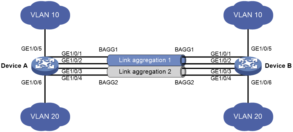
Network configuration
On the network shown in Figure 7, perform the following tasks:
· Configure Layer 2 static aggregation groups 1 and 2 on Device A and Device B, respectively.
· Enable VLAN 10 at one end of the aggregate link to communicate with VLAN 10 at the other end.
· Enable VLAN 20 at one end of the aggregate link to communicate with VLAN 20 at the other end.
· Configure link aggregation groups 1 and 2 to load share traffic across aggregation group member ports.
¡ Configure link aggregation group 1 to load share packets based on source MAC addresses.
¡ Configure link aggregation group 2 to load share packets based on destination MAC addresses.
Procedure
1. Configure Device A:
# Create VLAN 10, and assign the port GigabitEthernet 1/0/5 to VLAN 10.
<DeviceA> system-view
[DeviceA] vlan 10
[DeviceA-vlan10] port gigabitethernet 1/0/5
[DeviceA-vlan10] quit
# Create VLAN 20, and assign the port GigabitEthernet 1/0/6 to VLAN 20.
[DeviceA] vlan 20
[DeviceA-vlan20] port gigabitethernet 1/0/6
[DeviceA-vlan20] quit
# Create Layer 2 aggregate interface Bridge-Aggregation 1.
[DeviceA] interface bridge-aggregation 1
# Configure Layer 2 aggregation group 1 to load share packets based on source MAC addresses.
[DeviceA-Bridge-Aggregation1] link-aggregation load-sharing mode source-mac
[DeviceA-Bridge-Aggregation1] quit
# Assign ports GigabitEthernet 1/0/1 and GigabitEthernet 1/0/2 to link aggregation group 1.
[DeviceA] interface gigabitethernet 1/0/1
[DeviceA-GigabitEthernet1/0/1] port link-aggregation group 1
[DeviceA-GigabitEthernet1/0/1] quit
[DeviceA] interface gigabitethernet 1/0/2
[DeviceA-GigabitEthernet1/0/2] port link-aggregation group 1
[DeviceA-GigabitEthernet1/0/2] quit
# Configure Layer 2 aggregate interface Bridge-Aggregation 1 as a trunk port and assign it to VLAN 10.
[DeviceA] interface bridge-aggregation 1
[DeviceA-Bridge-Aggregation1] port link-type trunk
[DeviceA-Bridge-Aggregation1] port trunk permit vlan 10
[DeviceA-Bridge-Aggregation1] quit
# Create Layer 2 aggregate interface Bridge-Aggregation 2.
[DeviceA] interface bridge-aggregation 2
# Configure Layer 2 aggregation group 2 to load share packets based on destination MAC addresses.
[DeviceA-Bridge-Aggregation2] link-aggregation load-sharing mode destination-mac
[DeviceA-Bridge-Aggregation2] quit
# Assign ports GigabitEthernet 1/0/3 and GigabitEthernet 1/0/4 to link aggregation group 2.
[DeviceA] interface gigabitethernet 1/0/3
[DeviceA-GigabitEthernet1/0/3] port link-aggregation group 2
[DeviceA-GigabitEthernet1/0/3] quit
[DeviceA] interface gigabitethernet 1/0/4
[DeviceA-GigabitEthernet1/0/4] port link-aggregation group 2
[DeviceA-GigabitEthernet1/0/4] quit
# Configure Layer 2 aggregate interface Bridge-Aggregation 2 as a trunk port and assign it to VLAN 20.
[DeviceA] interface bridge-aggregation 2
[DeviceA-Bridge-Aggregation2] port link-type trunk
[DeviceA-Bridge-Aggregation2] port trunk permit vlan 20
[DeviceA-Bridge-Aggregation2] quit
2. Configure Device B in the same way Device A is configured. (Details not shown.)
Verifying the configuration
# Display detailed information about all aggregation groups on Device A.
[DeviceA] display link-aggregation verbose
Loadsharing Type: Shar -- Loadsharing, NonS -- Non-Loadsharing
Port Status: S -- Selected, U -- Unselected, I -- Individual
Port: A -- Auto port, M -- Management port, R -- Reference port
Flags: A -- LACP_Activity, B -- LACP_Timeout, C -- Aggregation,
D -- Synchronization, E -- Collecting, F -- Distributing,
G -- Defaulted, H -- Expired
Role: P -- Primary, S -- Secondary
Aggregate Interface: Bridge-Aggregation1
Aggregation Mode: Static
Loadsharing Type: Shar
Management VLANs: None
Port Status Priority Oper-Key Role
GE1/0/1(R) S 32768 1 None
GE1/0/2 S 32768 1 None
Aggregate Interface: Bridge-Aggregation2
Aggregation Mode: Static
Loadsharing Type: Shar
Management VLANs: None
Port Status Priority Oper-Key Role
GE1/0/3(R) S 32768 2 None
GE1/0/4 S 32768 2 None
The output shows that:
· Link aggregation groups 1 and 2 are both load-shared Layer 2 static aggregation groups.
· Each aggregation group contains two Selected ports.
# Display all the group-specific load sharing modes on Device A.
[DeviceA] display link-aggregation load-sharing mode interface
Bridge-Aggregation1 Load-Sharing Mode:
source-mac address
Bridge-Aggregation2 Load-Sharing Mode:
destination-mac address
The output shows that:
· Link aggregation group 1 distributes packets based on source MAC addresses.
· Link aggregation group 2 distributes packets based on destination MAC addresses.
