- Table of Contents
- Related Documents
-
| Title | Size | Download |
|---|---|---|
| 03-FAQ | 500.22 KB |
|
|
|
H3C CR16000-F Router Series FAQ |
|
|
|
|
Copyright © 2015-2019 New H3C Technologies Co., Ltd. All rights reserved.
No part of this manual may be reproduced or transmitted in any form or by any means without prior written consent of New H3C Technologies Co., Ltd.
Except for the trademarks of New H3C Technologies Co., Ltd., any trademarks that may be mentioned in this document are the property of their respective owners.
The information in this document is subject to change without notice.
Contents
Q. What models does the H3C CR16000-F router series include?
Q. Can I install MPUs of different models on the same router?
Q. Does the router support DC power supplies?
Q. Can the power supplies be hot swapped?
Q. Can power supplies of different models be installed on the same router?
Q. Can the cards/subcards be hot swapped?
Q. How are the interfaces numbered on the router?
Q. Does the router support active/standby MPU switchover?
Q. Can the fan speed automatically adjusted to adapt to the cooling requirements?
Q. Are the fan trays and power supplies hot swappable?
Q. What is the operating temperature and upper and lower temperature thresholds of the router?
Q. How do I identify the card serial number or manufacture information?
Q. Which cards does the router use for data forwarding?
Q. How do the switching fabric modules collaborate with each other?
Q. Can I install switching fabric modules of different types on the same router?
Q. What is the function of the console port on the switching fabric module?
Q. Does the router support CF cards?
Q. What protective measures do the power supplies use?
Q. What subcards are available for the SPEX/CSPEX cards?
Q. Does the router provide crossbar module redundancy?
Q. Do the service modules support interface type switching between POS and GE?
Q. Do the service modules support interface type switching between Ethernet and FlexE?
Q. Do the service modules support interface type switching between GE and XGE?
Q. Does the BootWare support forward compatibility?
Q. How do I view the system version information and operation time information?
Q. Can I delete the Comware system software image file after the upgrade is completed?
Q. How can I empty the recycle bin?
Q. Is software hotfix supported?
Q. What is the name of the default configuration file?
Q. What should I do before installing patches?
Q. Why doesn't the router display the current startup configuration file?
Q. System management and maintenance
Q. Information displayed on the console terminal is incorrect sometimes. Why?
Q. Data loss occurred after I logged in to the router through the console port. What should I do?
Q. How can I clear a Telnet connection?
Q. Can a Telnet user's username contain the at sign (@)?
Q. How do I format the CF card, SD card, or flash memory from the BootWare?
Q. How do I examine the memory of the router before the router starts up?
Q. Does the router relearn MAC address, ARP, and route entries after an active/standby switchover?
Q. Why should I wait for all LPUs to operate correctly before I save the running configuration?
Q. Can the management Ethernet interface come up without an IP address?
Q. How are packets arriving at the standby MPU's management Ethernet interface handled?
Q. How many chassis can an IRF fabric have?
Q. Can all types of service modules support IRF?
Q. Are there any special requirements for connecting IRF member chassis?
Q. Why can't I bind a physical interface to or remove it from an IRF port in IRF mode?
Q. Can I connect IRF physical interfaces over a relay device?
Q. Does an IRF fabric support multichassis Ethernet link aggregation?
Q. Can I set up an IRF connection that has multiple links?
Q. Can IRF member chassis use duplicate member IDs?
Q. Can I remove both the MPUs in a subordinate chassis?
Q. Can I run LACP MAD on any Ethernet link aggregations?
Q. Why are network interfaces that were shut down by MAD still down after an IRF merge?
Q. Why can't data traffic be forwarded at the wire speed across chassis in an IRF fabric?
Network security and attack prevention
Q. What attack prevention features does the router support?
Q. What roles can the router play when using different SSH versions?
Q. Why can the level for the RADIUS server (the router) only be 1 when it connects to an ACS server?
Q. Does the router support local authentication when HWTACACS authentication fails?
Q. Can the router be connected to a TACACS server that runs third-party TACACS server software?
Q. How do I set the user role?
Q. How are the levels of HWTACACS and Cisco's ACS matched?
Q. How do I prevent gateway spoofing when the router acts as a gateway?
Q. What is the maximum number of bits of a port count?
Q. Does the router support jumbo frames?
Q. How do different services handle packets larger than MTU?
Q. Does the MTU configuration affect only the fragmentation of packets sent to the CPU?
Q. Are the MAC address entries the same across the interface cards on the router?
Q. Can frames be correctly forwarded when the MAC address learning limit is set to 0?
Q. Why is a MAC address learned into multiple VLANs?
Q. Does the router support multicard link aggregation?
Q. How is traffic load shared for link aggregation on the router?
Q. Does the router support configuring static MAC address entries on an aggregate interface?
Q. What fields are displayed in the output transceiver module optical power information?
Q. How is the port rate percentage calculated?
Q. What types of subinterfaces on the router support VLAN termination?
Q. Does the router support Layer 3 subinterface statistics collection?
Q. Does the router support configuring a secondary IP address for a Layer 3 Ethernet interface?
Q. What is the MAC address of a VLAN interface used for?
Q. Does the router support the super VLAN configuration?
Q. How does the router handle an ICMP ping packet whose size exceeds 1500 bytes?
Q. Is the sending interval of ICMP ping packets configurable on the router?
Q. Does the router support cross-card port mirroring?
Q. Does the router support remote port mirroring?
Q. What tunneling technologies does the router support?
Q. What protocols and features does BFD support on the router?
Q. Which load sharing modes are supported by the router?
Q. Does the router support configuring blackhole routes?
Q. Is the OSPF cost of a Layer 3 Ethernet interface on the router relevant to the interface rate?
Q. What are the preferences of different routing protocols?
Q. What are the possible reasons for the OSPF CONFIG ERROR trap?
Q. Does the router discard the matching packets when the PBR-based forwarding fails?
Q. How do I filter LSPs triggered by routes with non-32-bit masks?
Q. How do I view the tracert path correctly after enabling TTL propagation for the router?
Q. Which IGMP versions are supported by the router?
Q. Are static RPs supported by the router?
Q. Are static multicast routes supported by the router?
Q. How do I deny multicast packets from an illegal multicast source?
Q. Are multicast group policies supported by the router?
Q. Is inter-AS MD VPN supported by the router?
Q. Are QoS policy, port mirroring, and flow mirroring are supported on logical interfaces?
Q. What if both redirection and traffic policing are associated with one class in a QoS policy?
Q. What are the traffic priorities for CBQ?
Q. What is the default action in a QoS traffic behavior?
Q. How can I view the rate limit values for protocol packets to the control plane?
Q. What are the restrictions and guidelines for configuring an ATM P2P/P2MP subinterface?
Q. Can OAM continuity check be enabled on only one end of the network?
Q. Must the network types of the OSPF interfaces on both ends of an ATM network be the same?
Q. How does the router perform NAT?
Q. Do I need to configure a QoS policy to redirect packets to be NATed to a NAT service card?
Q. Which cards can support CGN?
Q. What CGN services are supported on the CGN cards?
Q. What unification methods are supported on the CGN cards?
Q. Which BRAS access methods does the router support?
Q. What are the guidelines for setting the interval for packet statistics collection?
Q. What are the commonly used BRAS debugging commands?
Q. Do I need to specify an IPv4 address for a VT interface?
Q. Why is an L2TP session deleted?
Q. How are tunnel attributes issued when an L2TP tunnel is established?
Q. What types of IPoE users does the router support?
Q. Do I need to enable the function of restoring abnormally logged-out DHCP IPoE users?
Q. What types of NQA operations are supported?
Q. Is clock synchronization required when you configure iFIT?
Q. How can I obtain information about support for SRv6 on cards in different operating modes?
Q. Can a CGN card support SRv6 TE policies?
Hardware
This section contains the most frequently asked questions about the router hardware.
Q. What models does the H3C CR16000-F router series include?
A. See Appendix A in the installation guide for the router series.
Q. Can I install MPUs of different models on the same router?
A. No. The active and standby MPUs on a router must be the same model. If they are not the same model, the standby MPU will fail to start up.
Q. Does the router support DC power supplies?
A. Yes. The router supports AC and DC power supplies.
Q. Can the power supplies be hot swapped?
A. Yes.
Q. Can power supplies of different models be installed on the same router?
A. No.
Q. Can the cards/subcards be hot swapped?
A. Cards can be hot swapped. Subcards except the MIC-SM can be hot swapped.
Q. How are the interfaces numbered on the router?
A. In IRF mode, the interfaces on the router are numbered in the interface-type A/B/C/D format. In standalone mode, the interfaces on the router are numbered in the interface-type B/C/D format.
· A—IRF member ID of the chassis.
· B—Slot number of the card.
· C—Subslot number. If the card does not have a subslot, the subslot number is 0.
· D—Interface number.
Q. Does the router support active/standby MPU switchover?
A. Yes. The standby MPU automatically takes over when the active MPU fails or is manually rebooted, to ensure service continuity.
For a successful active/standby switchover, make sure the active and standby MPUs run the same software version.
Q. Can the fan speed automatically adjusted to adapt to the cooling requirements?
A. Yes.
Q. Are the fan trays and power supplies hot swappable?
A. Yes. As a best practice, hot-swapping a component when there is a minimum influence on the service and finish the hot-swapping as quickly as possible.
To avoid card damage and power-off protection of the router, finish hot-swapping a fan tray within 2 minutes.
Q. What is the operating temperature and upper and lower temperature thresholds of the router?
A. The operating temperature of the router is in the range of 0°C (32°F) to 45°C (113°F).
You can use the display environment command to display the router temperature statistics, including the current temperature and temperature thresholds.
· When the temperature drops below the lower threshold or reaches the warning threshold, the router displays a log message and a trap.
· When the temperature reaches the alarm threshold, the router repeatedly displays log and trap messages. It also alerts the user to the high-temperature condition through LEDs on the panel.
· When the temperature reaches the shutdown threshold, the router generates a log message and a trap, and the cards automatically power off.
Q. How do I identify the card serial number or manufacture information?
A. Use the display device manuinfo command on the router.
[Sysname]display device manuinfo
Q. Which cards does the router use for data forwarding?
A. The router uses switching fabric modules for data forwarding.
Q. How do the switching fabric modules collaborate with each other?
A. Multiple switching fabric modules on the router share the traffic load:
· When a switching fabric module is removed, the remaining switching fabric modules share the traffic load.
· When a new switching fabric module is installed, the existing switching fabric modules share the traffic load.
Q. Can I install switching fabric modules of different types on the same router?
A. Type-B, Type-D, Type-E, and Type-T switching fabric modules have different switching capacities. For best performance, do not install switching fabric modules of different types on the same router.
Q. What is the function of the console port on the switching fabric module?
A. The console port on the switching fabric module is intended for H3C Support to access the switching fabric module for troubleshooting and maintenance. Before you use this port, make sure you understand the impact of any operations you perform through this port.
Q. Does the router support CF cards?
A. The CSR05SRP1P1, CSR05SRP1P3-G, CSR05SRP1R3A, and CSR05SRP1R3 MPUs do not support CF cards. The other MPUs support CF cards.
Q. What protective measures do the power supplies use?
A. The power supplies adopt the following protective measures:
· Input protection—Input over-voltage protection, input under-voltage protection, and input over-current protection.
· Output protection—Output over-voltage protection, output over-current protection, output short-circuit protection, and output over-temperature protection.
Q. What subcards are available for the SPEX/CSPEX cards?
A. See Appendix B in the installation guide for the router.
Q. Does the router provide crossbar module redundancy?
A. Yes. Crossbar modules are built in switching fabric modules, and crossbar module redundancy is implemented through switching fabric module redundancy.
Q. Do the service modules support interface type switching between POS and GE?
A. Only the MIC-TCP8L and PIC-TCP8L subcards support interface type switching between POS and GE.
Q. Do the service modules support interface type switching between Ethernet and FlexE?
A. Only the CEPC-CQ8L, RX-NIC-CQ1LF, RX-NIC-CQ2LF, RX-NIC-LGQ2L, and RX-NIC-LGQ4L service modules support interface type switching between Ethernet and FlexE.
Q. Do the service modules support interface type switching between GE and XGE?
A. Only the following subcards support switching the interface type between GE and XGE:
· All interfaces on the MIC-XP20LA, NIC-XP10L, NIC-XP20L, RX-NIC-XP5L, RX-NIC-XP10L, and RX-NIC-XP20L subcards.
· The last four interfaces on a MIC-XP5L, MIC-XP5L1, or MIC-XP5L2 subcard.
Software
This section contains the most frequently asked questions about the router software.
Q. Does the BootWare support forward compatibility?
A. Yes. After a software upgrade, you can roll back the Comware system software without rolling back the BootWare.
Q. How do I view the system version information and operation time information?
A. Use the display version command. This command displays information about the current BootWare version, Comware system software version, and system operation time.
Q. Can I delete the Comware system software image file after the upgrade is completed?
A. No. The file contains the software images for MPUs and the software images for LPUs. MPUs and LPUs read these images during startup.
Q. Can I view deleted files?
A. Yes if the files were deleted by a delete command without the /unreserved option. A delete command with the /unreserved option permanently deletes files. A delete command without the /unreserved option moves commands to the recycle bin.
To view the commands in the recycle bin, use the dir /all command. The name of a file in the recycle bin is placed in brackets ([ ]).
You can use the undelete command to restore commands from the recycle bin.
Q. How can I empty the recycle bin?
A. Use the reset recycle-bin command. If a file in the recycle bin is corrupt, use the reset recycle-bin command with the /force option to delete the file.
Q. Is software hotfix supported?
A. Yes.
Q. What is the name of the default configuration file?
A. The name of the default configuration file is flash:/startup.cfg.
Q. What should I do before installing patches?
A. Before installing patches, perform the following tasks:
· Save the patch image file in the same directory on the same type of storage medium (CF card, SD card, or flash memory) on the MPUs. Only the CSR05SRP1P3 and CSR05SRP1P1 MPUs support SD cards.
· Specify the path of the patch image file for the patch file location argument.
Q. Why doesn't the router display the current startup configuration file?
A. The router does not display the current startup configuration file at the first startup:
<Sysname>display startup
MainBoard:
Current saved-configuration file: NULL
Next main startup saved-configuration file: flash:/startup.cfg
Next backup startup saved-configuration file: NULL
SlaveBoard:
Current saved-configuration file: NULL
Next main startup saved-configuration file: flash:/startup.cfg
Next backup startup saved-configuration file: NULL
Q. System management and maintenance
This section contains the most frequently asked questions about system management and maintenance.
Q. Information displayed on the console terminal is incorrect sometimes. Why?
A. If nothing is displayed on the console terminal, examine the following:
· Whether the power system is operating correctly.
· Whether the MPUs are operating correctly.
· Whether the console cable is connected to the console port correctly.
If no problem is found, the reason might be one of the following:
· The access port specified for the terminal is different from the port to which the console cable is connected.
· Settings on the configuration terminal are incorrect.
· The cable has a problem.
If garbled characters are displayed on the terminal, settings on the configuration terminal might be incorrect.
The correct terminal settings are as follows:
· Bits per second—9600 bps
· Flow control—None
· Parity—None
· Stop bits—1
· Data bits—8
· Terminal display type—VT100
If you are running the terminal software SecureCRT, you must deselect the DTR/DSR option and RTS/CTS option for flow control. By default, the RTS/CTS option is selected for flow control.
Q. Data loss occurred after I logged in to the router through the console port. What should I do?
A. Perform the following tasks:
1. Enter console user interface view.
2. Use the speed command to change the data rate to 115200 bps.
3. Close the connection.
4. Initiate a new console connection.
Q. How can I clear a Telnet connection?
A. Use the free user-interface vty number command in user view.
Q. Can a Telnet user's username contain the at sign (@)?
A. The username of a Telnet user that is configured on the router cannot contain the at sign (@).
Q. I cleared the packet statistics on an interface by using the reset counters interface command. Why does the MIB browser show that the error packet count is still the same?
A. The MIB browser shows the values of the hardware counters. The reset counters interface command does not reset the hardware counters. This command clears only the statistics calculated by software.
Q. How do I format the CF card, SD card, or flash memory from the BootWare?
A. To format the CF card, SD card, or flash memory:
1. Access the extended BootWare menu.
2. Access the storage media management menu and select the storage medium to be formatted.
3. Format the storage medium.
Procedure:
For example, to format the flash memory:
1. Power on or reboot the router.
The startup information appears. (Details not shown.)
2. Press Ctrl + B within three seconds after the "Press Ctrl+B to access EXTENDED-BOOTWARE MENU..." prompt message appears.
The extended BootWare menu appears.
==========================<EXTENDED-BOOTWARE MENU>==========================
|<1> Boot System |
|<2> Enter Serial SubMenu |
|<3> Enter Ethernet SubMenu |
|<4> File Control |
|<5> Restore to Factory Default Configuration |
|<6> Skip Current System Configuration |
|<7> BootWare Operation Menu |
|<8> Skip Authentication for Console Login |
|<9> Storage Device Operation |
|<0> Reboot |
============================================================================
Ctrl+Z: Access EXTEND-ASSISTANT MENU
Ctrl+F: Format File System
Enter your choice(0-9): 9
3. Enter 9 to access the storage media management menu.
==============================<DEVICE CONTROL>==============================
|<1> Display All Available Nonvolatile Storage Device(s) |
|<2> Set The Operating Device |
|<3> Set The Default Boot Device |
|<0> Exit To Main Menu |
============================================================================
Enter your choice(0-3): 2
4. Enter 2 to specify the operating storage medium.
Please set the operating device:
============================================================================
|Note:the operating device is flash |
|NO. Device Name File System Total Size Available Space |
|1 flash JFFS2 503808KB 9604KB |
|2 cfa0 FAT 4088468KB 3685136KB |
|0 Exit |
============================================================================
Enter your choice(0-2):1
Set the operation device successful!
5. Enter 1 to use the flash memory as the operating storage medium.
==============================<DEVICE CONTROL>==============================
|<1> Display All Available Nonvolatile Storage Device(s) |
|<2> Set The Operating Device |
|<3> Set The Default Boot Device |
|<0> Exit To Main Menu |
============================================================================
Enter your choice(0-3): 0
6. Enter 0 to return to the extended BootWare menu.
==========================<EXTENDED-BOOTWARE MENU>==========================
|<1> Boot System |
|<2> Enter Serial SubMenu |
|<3> Enter Ethernet SubMenu |
|<4> File Control |
|<5> Restore to Factory Default Configuration |
|<6> Skip Current System Configuration |
|<7> BootWare Operation Menu |
|<8> Skip Authentication for Console Login |
|<9> Storage Device Operation |
|<0> Reboot |
===========================================================================
Ctrl+Z: Access EXTENDED ASSISTANT MENU
Ctrl+F: Format File System
Enter your choice(0-9):
Warning:All files on flash will be lost! Are you sure to format? [Y/N] Y
7. Press Ctrl+F to format the flash memory.
Q. How do I examine the memory of the router before the router starts up?
A. Power on the router and press Ctrl+T or Ctrl+Y as prompted.
Press Ctrl+T to start the 5-step memory test procedure:
DDR2 SDRAM test successful.
System is starting...
Press Ctrl+D to access BASIC-BOOTWARE MENU...
Press Ctrl+T to start memory test
Running five-step RAM test...
This operation may take several minutes. Please wait...
DDR2 SDRAM dataline testing... [ PASS ]
DDR2 SDRAM addressline testing... [ PASS ]
Five-step RAM test succeeded.
System is starting...
Press Ctrl+Y to start the 9-step memory test procedure:
DDR2 SDRAM test successful.
Press Ctrl+T to start five-step full RAM test...
Press Ctrl+Y to start nine-step full RAM test...
Running Nine-Step RAM test…
This operation may take several minutes. Please wait...
DDR2 SDRAM dataline testing... [ PASS ]
DDR2 SDRAM addressline testing... [ PASS ]
DDR2 SDRAM unit testing... [ PASS ]
Nine-Step ram test successful.
System is starting...
Press Ctrl+D to access BASIC-BOOTWARE MENU...
Booting Normal Extend BootWare
The Extend BootWare is self-decompressing.....................Done!
Q. Does the router relearn MAC address, ARP, and route entries after an active/standby switchover?
A. The router relearns route entries, but it does not relearn MAC address entries and ARP entries.
The switchover does not interrupt MAC-based forwarding or ARP services because the MAC address table and the ARP table are backed up on the standby MPU. The impact on routing-based forwarding services depends on the configuration of GR or NSR:
· If GR or NSR is configured, the switchover will not interrupt forwarding services.
· If GR or NSR is not configured, the switchover will interrupt forwarding services.
Q. Why should I wait for all LPUs to operate correctly before I save the running configuration?
A. The configuration is saved on the flash memory or CF card. During startup, the router configures LPUs by loading the configuration to memory. If you execute the save command before the process is completed, the incomplete configuration in memory will be saved to the flash memory to replace the complete configuration, resulting in configuration loss.
Q. Can the management Ethernet interface come up without an IP address?
A. Yes. The interface can come up as long as the Layer 2 link is up. In addition, flow control is performed on the interface by software, and excessive packets arriving at the interface cannot affect system operation.
Q. I was using TFTP to transfer data from the router. Why did the transfer fail when the amount of transferred data reached about 32 MB?
A. This problem is caused by the TFTP server. Some TFTP servers have a limit of 32 MB on a transferred data block. When the amount of transferred data for the block reaches approximately 32 MB, the TFTP server stops requesting data transfer. If you experience this problem, please change the TFTP server software.
Q. How are packets arriving at the standby MPU's management Ethernet interface handled?
A. Packets are discarded on the standby MPU's management Ethernet interface. To access the device over Ethernet, use the management Ethernet interface on the active MPU or an Ethernet port on the interface card.
IRF
This section contains the most frequently asked questions about IRF.
Q. How many chassis can an IRF fabric have?
A. An IRF fabric can have a maximum of two member chassis. You must connect them in a daisy-chain topology. Ring topology is not supported.
Q. Can all types of service modules support IRF?
A. Yes. You can use all types of service modules in IRF mode.
Q. Are there any special requirements for connecting IRF member chassis?
A. Yes. When you connect two neighboring IRF members, you must connect the physical interfaces of IRF-port 1 on one member to the physical interfaces of IRF-port 2 on the other. The IRF fabric cannot be established if physical connections are incorrect.
When you bind physical interfaces to IRF ports, you must ensure that the bindings are consistent with the physical connections.
Q. Why can't I bind a physical interface to or remove it from an IRF port in IRF mode?
A. In IRF mode, you must shut down a physical interface before you bind it to or remove it from an IRF port. You cannot shut down the interface if one of the following conditions exists:
· The interface is the only member interface of a subordinate chassis in an IRF port binding.
· Among all interfaces of a subordinate chassis in an IRF port binding, only the interface is in up state.
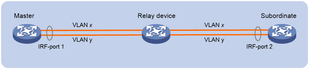
Q. Can I connect IRF physical interfaces over a relay device?
A. Yes. You can connect two distant IRF member devices through relay devices (for example, Layer 2 devices). To use relay devices, you must assign each IRF physical link a unique VLAN to send and receive IRF packets, as shown in Figure 1. The VLANs are called IRF packet VLANs.
If you are using a VLAN-based IRF deployment over Layer 2 relay devices, make sure the interfaces of the relay devices on each IRF physical link meet the following requirements:
· The spanning tree feature is disabled on all the interfaces.
· The link type of these interfaces cannot be access.
· If the link type of an interface is trunk, make sure the interface permits the traffic from the IRF packet VLAN to pass through and the IRF packet VLAN is not the PVID of the trunk interface.
· If the link type of an interface is hybrid, make sure the hybrid interface is a tagged member of the IRF packet VLAN.
Q. Does an IRF fabric support multichassis Ethernet link aggregation?
A. Yes.
Q. Can I set up an IRF connection that has multiple links?
A. Yes, you can bind multiple physical links into one IRF connection. These links aggregate automatically. You do not need to create a link aggregation group as you do for creating an Ethernet link aggregation.
Q. Can IRF member chassis use duplicate member IDs?
A. No. You must assign a unique IRF member ID to each member chassis before setting up an IRF fabric. If a chassis has different member IDs on its active MPU and the standby MPU, the standby MPU will reboot automatically with the member ID on the active MPU.
Q. Can I add an MPU to an IRF fabric if it runs a different software version than the global active MPU?
A. No. All MPUs in the IRF fabric must run the same version of software.
Q. Can I remove both the MPUs in a subordinate chassis?
A. No. Each subordinate chassis must have an MPU to communicate with the global active MPU and manage forwarding on the local chassis. If you remove both the MPUs on a subordinate chassis, its interface modules cannot communicate with each other to forward cross-card traffic correctly.
Q. Can I run LACP MAD on any Ethernet link aggregations?
A. No. To run LACP MAD, make sure the aggregation meets following requirements:
· The remote device is an IRF-capable device that can process the LACPDUs that convey the ActiveID field for MAD.
· The aggregation mode is dynamic.
· The aggregation includes a minimum of one link from each member chassis.
Q. Can I use an IRF fabric as the intermediate device to detect multi-active collisions for another IRF fabric?
A. Yes. You must assign the two IRF fabrics different domain IDs for correct split detection.
Q. Why are network interfaces that were shut down by MAD still down after an IRF merge?
A. If you reboot the active fabric instead of the recovery IRF fabric to complete an IRF merge, the network interfaces that were shut down by MAD cannot be restored automatically. You must use the mad restore command to restore their original physical state.
To avoid this issue, reboot the recovery IRF fabric instead of the active IRF fabric to complete an IRF merge.
Q. Why doesn't the running configuration on a reunified IRF fabric include the configuration that I made on one chassis after an IRF split?
A. When an IRF fabric merges, the chassis in the Recovery-state IRF fabric reboots with the running configuration on the active IRF fabric. The configuration you made on the recovery IRF fabric will not take effect.
Q. Will the active IRF fabric retain configuration for chassis in the recovery IRF fabric after an IRF split?
A. Yes. In the running configuration, the active IRF fabric will retain the settings for the chassis in the recovery IRF fabric. You do not need to reconfigure these settings after the recovery IRF fabric rejoins the active IRF fabric. However, the display current-configuration command does not display these settings on the active IRF fabric before a merge. You cannot save the settings to the configuration file on the active IRF fabric. The settings will be lost if the active IRF fabric reboots before an IRF merge occurs.
Q. Why can't data traffic be forwarded at the wire speed across chassis in an IRF fabric?
A. The following events can cause data traffic to not be forwarded at the wire speed across chassis in an IRF fabric:
· Tag removal on outgoing ports—Frames sent on IRF links always have a 4-byte VLAN tag. If the VLAN tag is removed on the outgoing port, the traffic rate will not reach the wire speed.
· Unbalanced traffic distribution—IRF distributes traffic across member chassis on a flow-by-flow basis. All traffic of a flow will be forwarded on the same IRF link. As a result, some IRF links might have heavy traffic while others have light traffic.
· Control traffic—Part of bandwidth is used for configuration synchronization and IRF protocol traffic (for example, IRF hello packets) between member chassis.
Network security and attack prevention
This section contains the most frequently asked questions about network security and attack prevention.
Q. What attack prevention features does the router support?
A. The router supports protection against link layer, ARP, network layer, and transport layer attacks, as shown in Table 1.
Table 1 Attack prevention types
|
Attack prevention types |
Description |
|
|
Link layer |
MAC address attack prevention |
Prevents the attack of packets with different source MAC addresses or VLANs by limiting the maximum number of MAC addresses that an interface can learn. |
|
STP packet attack protection |
Provides protection measures such as BPDU guard, root guard, loop guard, port role restriction, TC-BPDU transmission restriction, and TC-BPDU guard. |
|
|
ARP attack |
ARP source suppression |
Prevents IP attack packets from fixed sources. |
|
ARP black hole routing |
Prevents IP attack packets from sources that are not fixed. |
|
|
ARP active acknowledgement |
Prevents user spoofing. |
|
|
ARP safe-guard |
Prevents traffic-intensive ARP packet attacks. |
|
|
Source MAC-based ARP attack detection |
Prevents ARP packet attacks from the same source MAC. |
|
|
ARP packet source MAC consistency check |
Prevents attacks from ARP packets whose source MAC address in the Ethernet header is different from the sender MAC address in the message body. |
|
|
ARP packet rate limiting |
Prevents ARP packet attacks on a per-interface basis by limiting the rate of ARP packets delivered to the CPU when the number of incoming ARP packets exceeds the maximum ARP packet rate. |
|
|
ND attack |
Source MAC-based ND attack detection |
Prevents ND packet attacks from the same source MAC. |
|
ND packet rate limiting |
Prevents ND packet attacks on a per-interface basis by limiting the rate of ND packets delivered to the CPU when the number of incoming ND packets exceeds the maximum ND packet rate. |
|
|
Network layer |
uRPF check |
Protects a network against source spoofing attacks. |
|
TTL attack prevention |
Prevents an attack by disabling sending ICMP time exceeded messages. |
|
|
ICMP attack prevention |
Prevents the attack of excessive ICMP requests by enabling the hardware to reply to the requests. |
|
|
IGMP suppression |
Prevents IGMP packet attacks by limiting the IGMP packet rate on a per-MAC basis or by limiting the rate of IGMP packets delivered to the CPU on a per-interface basis. · Source-MAC-based IGMP suppression—When the number of IGMP packets from a MAC address exceeds the threshold within the check interval, the device drops IGMP packets from the MAC address. · Interface-based IGMP suppression—When the number of IGMP packets on an interface exceeds the threshold within the check interval, the device limits the rate for sending IGMP packets to the CPU. |
|
|
MLD suppression |
Prevents MLD packet attacks by limiting the MLD packet rate on a per-MAC basis or by limiting the rate of MLD packets delivered to the CPU on a per-interface basis. · Source-MAC-based MLD suppression—When the number of MLD packets from a MAC address exceeds the threshold within the check interval, the device drops MLD packets from the MAC address. · Interface-based MLD suppression—When the number of MLD packets on an interface exceeds the threshold within the check interval, the device limits the rate for sending MLD packets to the CPU. |
|
|
Malformed packet attack prevention |
Prevents malformed packet attacks by dropping the following received packets: · Land packets in which the source and destination IP addresses are the same and the source and destination ports are the same. · ICMP echo requests in which the destination IP address is a broadcast address. · Empty IP, TCP, or UDP packets that only have the header and do not have high-layer data. |
|
|
Source route option packet attack prevention |
Disables the device from processing packets that contain the source route option to prevent a forged source route option from affecting network failure troubleshooting and specific service transmission. |
|
|
Transport layer |
TCP SYN flood attack prevention |
An attacker sends a large number of SYN packets to a server. This causes the server to open a large number of half-open connections and respond to the requests. However, the server will never receive the expected ACK packets. Because all of its resources are bound to half-open connections, the server is unable to accept new incoming connection requests. After you enable TCP SYN flood attack prevention, the device enters attack detection state. When the number of received SYN packets reaches or exceeds the threshold within a check interval, the device changes to prevention state and rate limits (on a per-interface basis) or drops subsequent SYN packets (on a per-flow basis). |
|
UDP flood attack prevention |
A UDP flood attacker sends a large number of UDP packets to a target system within a short period of time. Busy processing these packets, the target system cannot respond to normal services. After you enable UDP flood attack prevention, the device enters attack detection state. When the number of received UDP packets reaches or exceeds the threshold during a check interval, the device changes to prevention state and rate limits (on a per-interface basis) or drops subsequent UDP packets (on a per-flow basis). |
|
|
Application layer |
Interface-based DHCP attack suppression |
Enables the device to drop DHCP packets that exceed the specified DHCP packet rate threshold. |
|
DHCP flood attack prevention |
Prevents DHCP flood attacks by limiting the DHCP packet rate on a per-MAC basis or by limiting the rate of DHCP packets delivered to the CPU on a per-interface basis. · MAC-based DHCP flood attack prevention—If the number of DHCP packets from the same MAC address reaches the upper limit in the detection duration, the server determines that the client is launching a DHCP flood attack and drops the DHCP packets from that client. · Interface-based DHCP flood attack prevention—If the number of DHCP packets received on an interface reaches the upper limit in the detection duration, the server determines that a DHCP flood attack occurs on the interface and limits the rate of DHCP packets that the interface delivers to the CPU. |
|
|
Application layer |
PPPoE PADI attack prevention |
Disables the server from replying to requests sent from a PPPoE user within a time period if the user performs the following operations: · Send excessive PADI packets to the server. · Come online or go offline frequently. |
Q. What roles can the router play when using different SSH versions?
A. Table 2 describes roles that the router supports when it uses different SSH versions.
Table 2 Router roles and SSH versions
|
Version |
SSH1 |
SSH2 |
|
SR8800-X |
Acts as the server. |
Acts as the server and the client. |
Q. Why cannot a user log in to an ACS authentication server through a console port when the router uses RADIUS authentication?
A. The user can log in to an ACS server through a console port only when you deselect the Login-Service option for the ACS server configuration.
Q. Why can the level for the RADIUS server (the router) only be 1 when it connects to an ACS server?
A. The symptom might occur when one of the following conditions takes place:
· The 2011/002 private attributes for the ACS server are not complete.
· The Login-Service attribute for the ACS server is not configured.
Q. Does the router support local authentication when HWTACACS authentication fails?
A. The router supports local authentication when a HWTACACS authentication fails because the server is not reachable.
The router does not support local authentication when a HWTACACS authentication fails because of an incorrect username or password.
To perform local authentication when the HWTACACS server is not reachable, specify a HWTACACS scheme, and then the local keyword when you configure the authentication method. For example, configure the default authentication method for the ISP domain abc as follows:
<Sysname> system-view
[Sysname] domain abc
[Sysname-isp-abc] authentication default hwtacacs-scheme hwtacacs1 local
Q. Can the router be connected to a TACACS server that runs third-party TACACS server software?
A. As long as the TACACS server is configured with the standard RADIUS protocol, the router can be connected to the server. The servers include ACS servers from Cisco and TACACS servers open to public (for example, free TACACS servers).
Q. Does the reply from a RADIUS server include the Login-Service option after the authentication succeeds?
A. It depends on whether a service type is specified on the server. If a service type is specified on the server, the reply includes the Login-Service option. If no service type is specified on the server, the reply does not include the Login-Service option.
Q. How do I set the user role?
A. You can set the user role in one of the following ways:
· Execute the user-role command in user line view or user line class view to assign a user role to a user line. Users who log in through the user line will get the user role.
· Execute the authorization-attribute user-role command in local user view to specify a user role for the local user account.
· If AAA remote authentication is used, set the user role on the remote server.
Q. How are the levels of HWTACACS and Cisco's ACS matched?
A. The 0 to 16 levels of HWTACACS and ACS are matched level by level.
Q. Which one of the user role configured in VTY user interface and the user role configured on a RADIUS server or a HWTACACS server is assigned to a Telnet user?
A. The user role configured on a RADIUS server or a HWTACACS server is assigned. Both the default user roles are network-operator.
For example, if the user role network-admin or level 15 is configured in VTY user interface, and no user role is configured on the server, the user role network-operator is assigned to the Telnet user.
If no user role is configured in VTY user interface, and the user role level 15 is configured on the server, the user role level 15 is assigned to the Telnet user.
The user role configured in VTY user interface is assigned only after the authentication-mode none command or the password command is executed.
Q. How do I prevent gateway spoofing when the router acts as a gateway?
A. When receiving an ARP packet from a device that acts as a gateway, the router (the gateway) sends a gratuitous ARP packet to modify the spoofed ARP entries. If a large number of attack packets exist, the router detects the incoming interface of the attack packets, captures the packets to obtain packet information, and applies an ACL to filter the attack packets.
Network access
This section contains the most frequently asked questions about network access.
Q. What is the maximum number of bits of a port count?
A. On the router, the port count can be up to 64 bits, and the port count will be reset after it exceeds 64 bits.
Q. What are the definitions of the error packet fields for input and output packets in the output from the display interface command?
A. Table 3 and Table 4 describe the error packet fields in the output from the display interface command.
Table 3 Error packet fields for input packets
|
Field |
Description |
|
input errors |
Statistics of error packets received by the port. |
|
runts |
Number of inbound runt frames shorter than 64 bytes, in correct format, and containing valid CRCs. |
|
giants |
Number of inbound giant frames larger than the maximum frame length supported on the interface and containing valid CRCs. |
|
throttles |
Number of inbound frames shorter than 64 bytes and containing CRC errors. |
|
CRC |
Total number of inbound frames that had a normal length, but contained CRC errors. |
|
frame |
Total number of inbound frames that contained unknown errors. |
|
overruns |
Number of packets dropped because the input rate of the port exceeded the queuing capability. This problem occurs when the network is congested. |
|
aborts |
Number of inbound frames with input description errors. |
|
ignored |
Number of inbound frames dropped because the receiving buffer of the incoming interface ran low. |
|
parity errors |
Number of inbound frames with parity errors. |
Table 4 Error packet fields for output packets
|
Field |
Description |
|
output errors |
Total number of packets with various sending errors. |
|
giants |
Number of outbound giant frames larger than the maximum frame length supported on the interface and containing valid CRCs. |
|
Underruns |
Number of packets dropped because the output rate of the interface exceeded the output queuing capability. |
|
buffer failures |
Number of packets dropped because the transmit buffer of the interface ran low. |
|
aborts |
Packets that failed to be forwarded at the MAC layer due to network congestion. |
|
deferred |
Number of frames that the interface operating in half duplex mode deferred to transmit because of detected collisions. |
|
collisions |
Number of frames that the interface stopped transmitting because Ethernet collisions were detected during transmission. |
|
late collisions |
Number of frames that the interface deferred to transmit and were buffered at the MAC layer. |
|
lost carrier |
Number of carrier losses during transmission. |
|
no carrier |
Number of times that the port failed to detect the carrier when attempting to send frames. |
The output packet errors seldom occur. Most packets errors are input packet errors.
· If error frames of the runts, giants, throttles, CRC, or frame type are received, you must identify whether the peer device or the link has failed.
· If overruns error frames are received, you must verify whether the link bandwidth of the local end is sufficient.
Q. Does the router support jumbo frames?
A. The router supports configuring an Ethernet interface to permit jumbo frames and setting the maximum jumbo frame size. If an incoming frame is longer than the maximum jumbo frame size, the router drops the frame. The maximum jumbo frame size varies by card. For more information, see the command references for the router.
Q. How do different services handle packets larger than MTU?
A. MPLS forwarding does not fragment oversized packets by default. If you execute the mpls mtu command on the MPLS public interface, L3VPN forwarded packets can be fragmented. If packets are forwarded on a P node, you must use the mpls l3vpn fragment enable command to enable fragmentation.
For regular Layer 3 forwarding, IPv4 protocol will fragment packets larger than the MTU by default. IPv6 protocol specifies no fragmentation and the packets will be sent directly to the CPU for processing.
In tunnel forwarding, IPv4 protocol will fragment packets larger than the MTU by default. IPv6 protocol does not fragment packets.
The tunnel packet fragmentation method is as follows:
· The inner layer packet is fragmented, and the fragmented packets are separately added with a tunnel header.
· Fragmentation of the encapsulated packet after adding the tunnel header.
The fragmentation of the inner layer packet and the fragmentation of the packet after adding the tunnel header will not occur at the same time.
Q. Does the MTU configuration affect only the fragmentation of packets sent to the CPU?
A. Yes.
Q. Are the MAC address entries the same across the interface cards on the router?
A. Yes. When MAC address entries change on a card, the MAC address entries are automatically synchronized to all cards.
Q. How long is the aging timer for dynamic MAC address entries? How are the dynamic MAC address entries aged?
A. By default, the aging time for dynamic MAC address entries is 5 minutes. To modify the aging time, use the mac-address timer aging command.
When a data flow enters a port, the MAC address of the data flow is dynamically learned. When the data flow continues to send traffic, the aging time of the MAC address entry continues to be refreshed, and the MAC address entry will not be aged. When the data flow stops sending traffic, the MAC address entry is aged after the aging time expires.
Q. Can frames be correctly forwarded when the MAC address learning limit is set to 0?
A. When the MAC address learning limit is set to 0 on a port, the port does not learn source MAC addresses. Destination unknown frames are broadcast in VLANs by default. To prevent the router from forwarding source-unknown frames after the MAC learning limit is reached, use the undo mac-address max-mac-count enable-forwarding command.
Q. Why does a port still have MAC address entries after the mac-address max-mac-count 0 command is configured on the port?
A. These MAC address entries are learned before the mac-address max-mac-count 0 command is configured to disable MAC address learning. When MAC address learning is disabled, the software waits for these MAC address entries to age out, or the MAC address entries can be deleted by using the undo mac-address command.
Q. Why is a MAC address learned into multiple VLANs?
A. The router learns MAC address entries in the MAC+VLAN method. When multiple VLANs receive packets with the same MAC address, all these VLANs will learn the MAC address.
Q. Does the router support multicard link aggregation?
A. Yes.
Rate-based load sharing is supported only when 1-GE and 10-GE interfaces or 10-GE and 100-GE interfaces are aggregated to form a single Ethernet link aggregation group.
Q. How is traffic load shared for link aggregation on the router?
A. By default, traffic is load-shared among member ports based on their rates.
The load sharing mode varies by card model. You can use the link-aggregation global load-sharing mode command to configure the global load sharing mode.
In a link aggregation group, traffic can be load shared across the Selected ports based on any of the following modes:
· Per-flow load sharing—Load shares traffic on a per-flow basis. The load sharing mode classifies packets into flows and forwards packets of the same flow on the same link. This mode can be one or any combination of the following traffic classification criteria:
¡ Source or destination MAC address.
¡ Source or destination port number.
¡ Ingress port.
¡ Source or destination IP address.
¡ Protocol number.
¡ MPLS label.
· Per-packet load sharing—Load shares traffic on a per-packet basis.
Q. Does the router support configuring static MAC address entries on an aggregate interface?
A. Yes.
Q. Does DLDP take effect when one fiber is connected in case that two fibers of a link are both disconnected?
A. No. When both ends of a link are down, DLDP neighborship cannot be established. As a result, DLDP does not take effect.
Q. What fields are displayed in the output transceiver module optical power information?
A. The router supports diagnosing transceiver modules. A port might come down if the Rx or Tx optical power of its transceiver module is out of the range. Verify that the transceiver modules are the same type at the two ends and the link is operating correctly if any of the following error messages is displayed:
· RX power is high!
· RX power is low!
· TX power is high!
· TX power is low!
Q. How is the port rate percentage calculated?
A. The port rate percentage is the ratio of the actual traffic to the total port bandwidth and describes the actual port bandwidth usage. When you calculate the port rate percentage, the inter-frame gap and the preamble must be added as follows:
(ulActualSpeed + 20 (preamble + inter-frame gap) * ulPktSpeed) * 8/ulRatedSpeed
· ulActualSpeed—Rate in kbps (the field in red) in the output.
· ulPktSpeed—Rate in pps (the field in blue) in the output.
· ulRatedSpeed—Port rate. For example, the port rate of a 10-GE port is 10000000000 bps.
[Sysname-Ten-GigabitEthernet3/1/2]display interface te-gigabitEthernet 3/1/2
Ten-GigabitEthernet3/1/2 current state: DOWN
IP Packet Frame Type: PKTFMT_ETHNT_2, Hardware Address: 00e0-fc00-0000
Description: Ten-GigabitEthernet3/1/2 Interface
Loopback is not set
……
Peak value of input: 0 bytes/sec, at 2000-04-26 12:00:32
Peak value of output: 0 bytes/sec, at 2000-04-26 12:00:32
Last 300 seconds input: 0 packets/sec 0 bytes/sec 0%
Last 300 seconds output: 0 packets/sec 0 bytes/sec 0%
Input (total): 0 packets, 0 bytes
- unicasts, - broadcasts, - multicasts
Input (normal): 0 packets, 0 bytes
0 unicasts, 0 broadcasts, 0 multicasts
Input: 0 input errors, 0 runts, 0 giants, 0 throttles
0 CRC, 0 frame, 0 overruns, - aborts
- ignored, - parity errors
Output (total): 0 packets, 0 bytes
- unicasts, - broadcasts, - multicasts, - pauses
Output (normal): 0 packets, 0 bytes
0 unicasts, 0 broadcasts, 0 multicasts, 0 pauses
Output: 0 output errors, - underruns, - buffer failures
0 aborts, 0 deferred, 0 collisions, 0 late collisions
- lost carrier, - no carrier
Q. Why is the peer port down and the local port not down when the port of the router is connected to the port of another device?
A. When fiber GE ports are connected and the local port is manually configured with a speed and duplex mode, the local port can go up only if the port can receive fiber signals. When the speed and duplex mode of the local port are autonegotiated, the local port goes down when the peer port goes down.
When fiber 10-GE ports of two routers of this router series are connected, the MAC layer will negotiate the port status. If one end detects local faults, the port will go down and send remote faults to notify the remote end. When the remote end detects remote faults, the remote port will go down.
When the port of the router connects to the port of a device not of this router series, the local port does not go down if both of the following conditions exist:
· The remote port is down but sends out fiber signals correctly.
· The remote port does not send remote faults.
Q. What are the restrictions and guidelines for configuring the duplex modes and rates for subcard interfaces?
A. For a 10-GE interface installed with GE transceiver module on an MIC-XP4L1, MIC-XP2L, and MIC-XP2L-LAN interface subcard of a CSPEX-1104-E card, you can set the duplex mode of the local and peer end to full and set the interface speed to 1000 Mbps. When configuring the duplex mode, follow these restrictions and guidelines:
· Fiber ports do not support the half keyword.
· For an interface subcard on a CSPEX-1104-E or CSPEX-1204 card, copper ports do not support the half duplex mode. For an interface subcard on other CSPEX cards, only the fiber ports on a MIC-GP4L interface subcard support the half duplex mode.
· For a GE interface on a MIC interface subcard of a CSPEX-1204 card, the full and half duplex modes at 10 or 100 Mbps is not supported.
When you configure the speed for a 10-GE interface subcard on the CSPEX-1304X, CSPEX-1404X, CSPEX-1502X, CSPEX-1504X, CSPEX-1504XA, CSPEX-1602X, CSPEX-1602XA, CSPEX-1804X, CSPEX-1512X, CSPEX-1612X, CSPEX-1812X, RX-SPE200, CEPC-XP4LX, CEPC-XP24LX, CEPC-XP48RX, CEPC-CP4RX, CEPC-CP4RXA, and CEPC-CP4RX-L cards, follow these restrictions and guidelines:
· Only the MIC-XP2L, MIC-XP2L-LAN, MIC-XP4L1, MIC-XP5L, MIC-XP5L1, MIC-XP20L, NIC-XP10L, NIC-XP20L, and NIC-XP20L1 interface subcards support switching the speed between 1000 Mbps and 10000 Mbps.
· After you execute the speed auto command on an interface on a MIC-XP2L, MIC-XP2L-LAN, MIC-XP4L1, MIC-XP5L, MIC-XP5L1, MIC-XP20L, NIC-XP10L, or NIC-XP20L interface subcard, the interface can negotiate a speed with its peer and operate at 10, 100, or 1000 Mbps.
· After you execute the speed auto command on an interface on a NIC-XP20L1 interface subcard, the interface can negotiate a speed with its peer and operate at 10, 100, 1000 or 10000 Mbps.
· Interfaces 1 and 2 on the MIC-XP2L or MIC-XP2L-LAN interface subcards form an interface group. When you switch the speed of an interface in this interface group, all interfaces in the interface group will switch the speed simultaneously.
· On a MIC-XP4L1 interface subcard, interfaces 1 and 3 form an interface group, and interfaces 2 and 4 form an interface group. When you switch the speed of an interface in an interface group, all interfaces in the interface group will switch the speed simultaneously.
· On a MIC-XP5L or MIC-XP5L1 interface subcard, interfaces 2 and 4 form an interface group, and interfaces 3 and 5 form an interface group. When you switch the speed of an interface in an interface group, all interfaces in the interface group will switch the speed simultaneously. Interface 1 on the MIC-XP5L or MIC-XP5L1 interface subcards does not support switching speed.
· On a MIC-XP20L interface subcard, interfaces 1 and 2 form an interface group, interfaces 3 and 4 form an interface group, interfaces 5 and 6 form an interface group, interfaces 7 and 8 form an interface group, interfaces 9 and 10 form an interface group, interfaces 11 and 12 form an interface group, interfaces 13 and 14 form an interface group, interfaces 15 and 16 form an interface group, interfaces 17 and 18 form an interface group, and interfaces 19 and 20 form an interface group. When you switch the speed of an interface in an interface group, all interfaces in the interface group will switch the speed simultaneously.
· On a NIC-XP10L interface subcard, interfaces 1 and 2 form an interface group, interfaces 3 and 4 form an interface group, interfaces 5 and 6 form an interface group, interfaces 7 and 8 form an interface group, and interfaces 9 and 10 form an interface group. When you switch the speed of an interface in an interface group, all interfaces in the interface group will switch the speed simultaneously.
· On a NIC-XP20L interface subcard, interfaces 1 and 4 form an interface group, interfaces 2 and 6 form an interface group, interfaces 3 and 7 form an interface group, interfaces 5 and 8 form an interface group, interfaces 9 and 12 form an interface group, interfaces 10 and 11 form an interface group, interfaces 13 and 16 form an interface group, interfaces 14 and 15 form an interface group, and interfaces 17 and 20 form an interface group, and interfaces 18 and 19 form an interface group. When you switch the speed of an interface in an interface group, all interfaces in the interface group will switch the speed simultaneously.
· When you switch the speed of a NIC-XP20L1 interface subcard, you can switch the speed on a single port.
When you configure the speed for a 10-GE interface subcard on a CSPEX-1802X, CSPEX-1802XA, CSPEX-1812X-E, CSPEX-2304X-G, CEPC-CQ8L, CEPC-CQ8LA, CEPC-CQ16L1, and RX-SPE200-E card, follow these restrictions and guidelines:
· Only the NIC-XP20L1 interface subcards support switching the speed between 1000 Mbps and 10000 Mbps.
· After you execute the speed auto command on a NIC-XP20L1 interface subcard, the interface can negotiate a speed with its peer and operate at 10, 100, 1000 or 10000 Mbps.
· When you switch the speed of a NIC-XP20L1 interface subcard, you can switch the speed on a single port.
The speed of a GE interface on a PIC-TCP8L interface subcard supports only autonegotiation, and can only be negotiated to 1000 Mbps.
When you configure the speed for interfaces on a NIC-XP5L, NIC-XP10L, and NIC-XP20L interface subcard of the CSPEX-2612X-E and CSPEX-1802XA card, follow these restrictions and guidelines:
· Interfaces on a NIC-XP5L subcard support only 10000 Mbps.
· You can use the speed 1000, speed 10000, using gigabit, or using tengige command to switch the speed of the NIC-XP10L and NIC-XP20L interface subcard between 1000 Mbps and 10000 Mbps. The speed auto command is not supported.
· Interfaces on a NIC-XP10L or NIC-XP20L subcard do not support 10 Mbps or 100 Mbps.
When you configure interface speed, follow these restrictions and guidelines:
· 40-GE and 100-GE interfaces can only operate at the maximum speed.
· Interfaces on a MIC interface subcard of the CSPEX-1104-E and CSPEX-1204 cards support the 1000 and auto keywords.
· When you configure the speed as auto for a 10-GE interface subcard on a CSPEX-1304X, CSPEX-1404X, CSPEX-1502X, CSPEX-1504X, CSPEX-1504XA, CSPEX-1602X, CSPEX-1602XA, CSPEX-1802XA, CSPEX-1804X, CSPEX-1512X, CSPEX-1612X, CSPEX-1812X, RX-SPE200, RX-SPE200-E cards, only the NIC-XP20L1 interface subcard supports 10-GE transceiver modules.
· For a 10-GE interface subcard on a CSPEX-1802X and CSPEX-1812X-E cards, only the NIC-XP20L1 interface subcard supports speed switching.
· For a 10-GE interface subcard on the CSPEX-2304X-G card that supports GE or 10-GE speed switching, when the 10-GE interface subcard switches to GE, the auto keyword is not supported, and only the 1000 keyword is supported.
The MIC-CQ1L2 interface subcard only supports switching the speed between 40-GE and 100-GE, and only supports full duplex mode.
When the interface subcard is on the CSPEX-2304X-G card, the minimum speed of the Ethernet interface on the interface subcard is 1000 Mbps. The interface does not support switching the speed between 10 Mbps and 100 Mbps, and does not support the half duplex mode.
The default duplex mode of the network management port on the CSR05SRP1R3 or CSR05SRP1P3-G MPU is autonegotiation, and the duplex command is not supported. The default speed is autonegotiation, and the speed command is not supported.
When you configure interface speed of an MIC-XP10L-M card, follow these restrictions and guidelines:
Q. What types of subinterfaces on the router support VLAN termination?
A. Layer 3 Ethernet subinterfaces, Layer 3 aggregate subinterfaces, L2VE subinterface, L3VE subinterface, slot-based L3VE subinterface, and FlexE service subinterface support the following types of VLAN termination:
· Ambiguous Dot1q termination.
· Unambiguous Dot1q termination.
· Ambiguous QinQ termination.
· Unambiguous QinQ termination.
· Untagged termination.
· Default termination.
Q. What is the difference between regular termination and user VLAN termination? What are the usage scenarios?
A. According to the creation method of VLAN termination related entries, VLAN termination on sub-interfaces include regular termination and user VLAN termination.
· Regular termination—Includes regular Dot1q termination (vlan-type dot1q vid) and regular QinQ termination (vlan-type dot1q vid second-dot1q). After configuration, the device will immediately create entries to record the configured VLAN termination information.
· User VLAN termination—Includes user VLAN Dot1q termination (user-vlan dot1q vid), user VLAN QinQ termination (user-vlan dot1q vid second-dot1q), and user VLAN Default termination (user-vlan dot1q default). After configuration, the device will only dynamically create entries for online users in the specified VLAN to save system resources.
User VLAN termination is suitable for BRAS user access scenarios, such as IPoE or PPPoE networking.
Q. Does the router support Layer 3 subinterface statistics collection?
A. Yes. Use the traffic-statistic enable command to enable Ethernet interface statistics collection.
IP forwarding services
This section contains the most frequently asked questions about IP forwarding services.
Q. Does the router support configuring a secondary IP address for a Layer 3 Ethernet interface?
A. Yes. You can configure a secondary IP address for a Layer 3 Ethernet interface of the router. The secondary IP address has similar functions to the primary IP address. The secondary IP address cannot be used for multicast. The users on the network segment to which the secondary IP address belongs cannot receive any multicast packets or establish OSPF neighbor relationship.
In addition, you can configure secondary IP addresses for any Layer 3 interfaces, including Layer 3 Ethernet interfaces (subinterfaces), Layer 3 aggregate interfaces (subinterfaces), and VLAN interfaces.
Q. Is the secondary IP address still valid when the primary IP address is removed from a Layer 3 Ethernet interface?
A. Yes. The primary and secondary IP addresses are independent on a Layer 3 Ethernet interface. The secondary IP address on a Layer 3 Ethernet interface is still valid after you remove the primary IP address from that interface.
Q. What is the MAC address of a VLAN interface used for?
A. When an Ethernet interface operates in bridge mode (configured with the port link-mode bridge command), the router examines the MAC address of a packet received on the interface. If the MAC address of the packet matches the MAC address of the VLAN interface, the router forwards the packet at Layer 3 or sends the packet through MPLS network. If not, the router forwards the packet at Layer 2.
Q. Does the router support the super VLAN configuration?
A. Yes.
Q. Which route in the FIB table has higher priority for packet forwarding when a route obtained from the routing table conflicts with a host route obtained from the ARP table?
A. The route with a 32-bit mask obtained from the routing table has a higher priority.
Q. How does the router handle an ICMP ping packet whose size exceeds 1500 bytes?
A. When sending an ICMP echo request whose size (including the IP header) exceeds 1500 bytes (the default MTU value), the router fragments the packet. If the Don't fragment flag is set, the packet fails to be sent out.
When receiving an ICMP echo request that exceeds 1500 bytes, the router can process the request and respond with an ICMP echo reply if configured with jumbo frame support. The router fragments the reply if its size exceeds 1500 bytes.
Q. Is the sending interval of ICMP ping packets configurable on the router?
A. Upon receiving an ICMP echo request, the CPU of the router responds with an ICMP echo reply.
Upon receiving an ICMP echo reply, the router sends the next request by default. If no reply is received, the router sends the next request when the aging timer expires. By default, the aging timer is 2 seconds.
If you specify the -m interval option in the ping command, the router sends the next ICMP echo request at the specified interval after receiving an ICMP echo reply.
Q. Does the router support cross-card port mirroring?
A. The local mirroring group supports cross-card port mirroring. The mirroring source and destination can reside on different cards of a router.
Q. Does the router support remote port mirroring?
A. Yes. The router supports remote port mirroring.
Q. What tunneling technologies does the router support?
A. The router supports the following tunneling technologies:
· ADVPN tunneling. For more information, see ADVPN configuration in Layer 3—IP Services Configuration Guide.
· GRE tunneling. For more information, see GRE configuration in Layer 3—IP Services Configuration Guide.
· IPv6 over IPv4 tunneling—Enables IPv6 packets to traverse IPv4 networks and enables isolated IPv6 networks to communicate.
· IPv4 over IPv4 tunneling/GRE tunneling—Creates VPN to ensure communication security.
· IPv4 over IPv6 tunneling—Adds an IPv6 header to IPv4 packets so that the IPv4 packets can pass an IPv6 network through a tunnel to realize interworking between isolated IPv4 networks.
· MPLS TE tunneling—Implements traffic engineering to prevent network congestion.
· VXLAN tunneling—Uses a MAC-in-UDP technology to provide Layer 2 connectivity between distant network sites across an IP network. VXLAN is typically used in data centers for multitenant services.
· SR-MPLS tunneling—Supports segment routing based on existing MPLS framework. After an SR-MPLS tunnel is established, you need to steer service packets to the tunnel. The service packets that can be steered to and forwarded by the SR-MPLS tunnel include public network, L3VPN, VPLS, and EVPN service packets.
· SRv6 tunneling—Supports segment routing based on IPv6 framework. The tunnel ingress node encapsulates data packets with an IPv6 basic header and an SRH. The transit nodes use the SIDs in the SRH to replace the destination IPv6 address of the packets and forward the packets. The egress node executes the functions corresponding to the last SID.
Q. What protocols and features does BFD support on the router?
A. BFD supports the following protocols and features:
· BFD for IPv4 routing protocols, including IPv4 static routing, RIP, OSPF, IS-IS, BGP, and PIM.
· BFD for IPv6 routing protocols, including IPv6 static routing, OSPFv3, IPv6 IS-IS, IPv6 BGP, and IPv6 PIM.
· BFD for MPLS features, including LSP, MPLS TE, and PW.
· BFD for policy-based routing and Track.
· BFD for IP FRR and MPLS TE FRR.
· BFD for Ethernet link aggregation.
· BFD for interface.
· BFD for MAD.
· BFD for SRv6 PW.
· SBFD/BFD echo for SRv6 TE policy.
To meet the requirements for high-performance and large-scale service rapid detection, you can use hardware BFD. In hardware BFD, the CPU completes session parameter negotiation on the control plane and the hardware completes high-speed detection on packet transmission and reception. This feature requires the support of special network chips. For more information, see BFD configuration in High Availability Configuration Guide.
Q. Which load sharing modes are supported by the router?
A. The router supports the following load sharing modes:
· Per-flow load sharing based on destination IP address of packets.
· Per-flow load sharing based on destination MAC address of packets.
· Per-flow load sharing based on destination port of packets.
· Per-flow load sharing based on source IP address of packets.
· Per-flow load sharing based on source MAC address of packets.
· Per-flow load sharing based on source port of packets.
· Per-flow load sharing based on IP protocol number of packets.
· Packet-based per-flow load sharing.
· Packet-based per-packet load sharing.
The default algorithm for packet-based per-flow load sharing is XOR16. Other algorithms include CRC16, CRC16XOR1, CRC16XOR2, CRC16XOR4, CRC16XOR8, and CRC16CCITT.
IP routing
This section contains the most frequently asked questions about IP routing.
Q. Does the router support configuring blackhole routes?
A. Yes. A blackhole route is a static route whose output interface is Null 0. The router discards the matching packets without sending ICMP messages to notify the source host. To prevent IP attacks, you can configure blackhole routes to discard packets destined for specific destinations. The following example shows how to configure a blackhole route:
<Sysname> system-view
[Sysname] ip route-static 1.1.1.1 32 null 0 preference 1
Q. Is the OSPF cost of a Layer 3 Ethernet interface on the router relevant to the interface rate?
A. Yes. By default, a Layer 3 Ethernet interface automatically computes its OSPF cost according to the interface rate with the following formula: Interface OSPF cost = Bandwidth reference value (100 Mbps) / Interface rate (Mbps).
If the calculated cost is greater than 65535, the value of 65535 is used. If the calculated cost is smaller than 1, the value of 1 is used.
Q. What are the preferences of different routing protocols?
A. Routing protocols, including static routing, each have a preference by default. If they find multiple routes to the same destination, the router selects the route with the highest preference as the optimal route. The preference of a direct route is always 0 and cannot be changed. You can configure a preference for each static route and each dynamic routing protocol. Table 5 lists the route types and default preferences. The smaller the value, the higher the preference.
Table 5 Route types and default route preferences
|
Route type |
Preference |
|
Direct route |
0 |
|
OSPF |
10 |
|
IS-IS |
15 |
|
Static route |
60 |
|
RIP |
100 |
|
OSPF ASE |
150 |
|
OSPF NSSA |
150 |
|
IBGP |
255 |
|
EBGP |
255 |
|
Unknown (route from an untrusted source) |
256 |
Q. What are the possible reasons for the OSPF CONFIG ERROR trap?
A. The following configuration errors cause the router to output the OSPF CONFIG ERROR trap:
· The local interface and its directly connected interface are on the same network segment but in different areas.
· The virtual link configuration is performed on the peer device but not on the router. When the router receives packets sent from the peer device through the virtual link, the router outputs the OSPF CONFIG ERROR trap.
Q. Does the router discard the matching packets when the PBR-based forwarding fails?
A. No. If the PBR-based forwarding fails because of nonexistent next hop, the router forwards the matching packets based on the IP routing table.
MPLS
This section contains the most frequently asked questions about MPLS.
Q. How do I filter LSPs triggered by routes with non-32-bit masks?
A. You can configure label acceptance policies on the router to achieve the purpose. A label acceptance policy uses an IP prefix list to control the label mappings received from a peer. This example uses LDP peer 1.1.1.9:
[Sysname]ip prefix-list host index 10 permit 0.0.0.0 0 greater-equal 32 less-equal 32
[Sysname]mpls ldp
[Sysname-mpls-ldp]accept-label peer 1.1.1.9 prefix-list host
After the configuration, the router accepts only the FEC-label mappings containing 32-bit prefixes from LDP peer 1.1.1.9.
To remove the label acceptance policy and accept non-32-bit prefixes from the LDP peer, execute the reset mpls ldp peer command. More LSPs will be created as a result, using up the LSP resources on the router.
Q. How do I view the tracert path correctly after enabling TTL propagation for the router?
A. To display the real path by using the tracert facility after TTL propagation is enabled, you must refresh the route entries.
IP multicast
This section contains the most frequently asked questions about IP multicast.
Q. Which IGMP versions are supported by the router?
A. The router supports IGMPv1, IGMPv2, and IGMPv3. By default, the router runs IGMPv2.
Q. Are static RPs supported by the router?
A. Yes. You can use the static-rp rp-address [ acl-number | bidir | preferred ] *command to configure a static RP. You can also use this command to define the multicast group range to which the static RP is designated and to give priority to the static RP.
When you configure a static RP, follow these restrictions and guidelines:
· If you specify the preferred keyword, the static RP takes priority. The dynamic RP takes effect only if the static RP fails. If you do not specify the preferred keyword, the dynamic RP takes priority.
· You must configure the same static RP for all routers in the PIM domain.
Q. Are static multicast routes supported by the router?
A. Yes. You can configure static multicast routes to create or change RPF routes.
Q. How do I deny multicast packets from an illegal multicast source?
A. You can configure an ACL to permit multicast packets only from legal sources. For example, to permit only packets from the source 99.100.100.4 to the group 225.1.1.1, follow these steps:
1. Configure an ACL.
[Sysname] acl advanced 3000
[Sysname-acl-ipv4-adv-3000] rule 0 permit ip source 99.100.100.4 0 destination 225.1.1.1 0
[Sysname-acl-ipv4-adv-3000] rule 1 deny ip
2. Use the source-policy command in PIM view to reference the configured ACL.
[Sysname-pim] source-policy 3000
Q. Are multicast group policies supported by the router?
A. Yes. You can configure a multicast group policy by using the igmp-snooping group-policy acl-number [ vlan vlan-list ] command in Layer 2 Ethernet interface view or Layer 2 aggregation interface view.
When you configure a multicast group policy, follow these restrictions and guidelines:
· Receiver hosts can join only the multicast groups that the specified ACL permits. If the specified ACL does not exist or the ACL does not have any valid rules, receiver hosts cannot join any multicast groups.
· The multicast group policy takes effect on all ports in the specified VLANs.
· The multicast group policy does not take effect on static member ports.
· When you execute this command in Layer 2 Ethernet interface view or Layer 2 aggregate interface view, one of the following occurs:
¡ If you do not specify a VLAN, this command takes effect on all VLANs to which the interface belongs.
¡ If you specify a VLAN, this command takes effect only when the interface belongs to the specified VLAN.
Q. The RPF check fails after the MSDP peer switchover in inter-domain multicast routing. What are the possible reasons?
A. The RPF check fails due to either of the following reasons:
· The configuration for the static RPF peer is not correct. For example, the filtering policy for the static RPF peer is incorrect.
· Loops exist between MSDP peers, causing packets to arrive at non-RPF interfaces.
Q. Is inter-AS MD VPN supported by the router?
A. Yes.
Q. Is IP multicast unavailable if I configure both of VPLS and IP multicast on the same interface of the router?
A. Yes. Do not configure both of VPLS and IP multicast on the same interface of the router.
QACL
This section contains the most frequently asked questions about QACL.
Q. Are QoS policy, port mirroring, and flow mirroring are supported on logical interfaces?
A. Table 6 shows the support of different logical interfaces for QoS policy, port mirroring, and flow mirroring.
Table 6 Support of different logical interfaces for QoS policy, port mirroring, and flow mirroring
|
Interface type |
QoS policy |
Port mirroring |
Flow mirroring |
Remarks |
|
Layer 3 aggregate interface |
Yes. Applied to the aggregate interface. |
The source port must be assigned to the aggregate interface as a member port. |
Yes. Applied to the aggregate interface. |
N/A |
|
Layer 3 aggregate subinterface |
Yes. Applied to the aggregate subinterface. |
The source port must be assigned to the aggregate subinterface as a member port. |
Yes. Applied to the aggregate subinterface. |
N/A |
|
Layer 2 aggregate interface |
Supported on only on member ports. |
The source port must be assigned to the aggregate interface as a member port. |
Supported on only on member ports. |
N/A |
|
VLAN interface |
A QoS policy cannot be applied in VLAN interface view, but can be applied in system view. A QoS policy applied in system view takes effect on both the Layer 2 traffic the entire VLAN and the Layer 3 traffic of the VLAN interface. |
The source port must be assigned to the VLAN. |
A QoS policy containing flow mirroring configuration cannot be applied in VLAN interface view, but can be applied in system view. A QoS policy applied in system view takes effect on both the Layer 2 traffic the entire VLAN and the Layer 3 traffic of the VLAN interface. |
N/A |
|
Tunnel interface |
Supported only in the inbound direction. |
The source port must be specified as the output interface for the tunnel packets. |
Supported only in the inbound direction. |
Supported only on CSPEX-1802X, CSPEX-1812X-E, and CEPC-CQ8L cards. |
Q. What if both redirection and traffic policing are associated with one class in a QoS policy?
A. The system first performs traffic policing to discard excess packets and then redirects conforming packets, regardless of the configuration order of the two actions.
Note that packets can be redirected only to internal ports of OAP cards.
Q. What are the traffic priorities for CBQ?
A. The matching traffic is enqueued according to the following rules:
· LLQ (EF)—When congestion does not occur, the excess traffic can be forwarded. When congestion occurs, the excess traffic is dropped preferentially.
· BQ (AF)—The excess traffic and traffic in BE queues (including the default BE queue) are scheduled by using WFQ.
· Default BE queue—Traffic does not match any criteria in CBQ is assigned to this queue.
On CSPEX-1204 cards, two CBQ modes are available: standard CBQ and advanced CBQ.
· Standard CBQ—The following types of traffic are in descending order of priority:
¡ Traffic within the minimum guaranteed bandwidth for EF.
¡ Traffic within the minimum guaranteed bandwidth for AF.
¡ Traffic beyond the minimum guaranteed bandwidth for AF and BE traffic.
¡ Traffic beyond the minimum guaranteed bandwidth for EF.
· Advanced CBQ—The following types of traffic are in descending order of priority:
¡ Traffic within the minimum guaranteed bandwidth for EF and traffic within the minimum guaranteed bandwidth for AF.
¡ Traffic beyond the minimum guaranteed bandwidth for EF, traffic beyond the minimum guaranteed bandwidth for AF, and traffic in BE queues configured with WFQ weights.
¡ Traffic in BE queues not configured with WFQ weights.
On CSPC-GE16XP4L-E, CSPC-GE24L-E, CSPC-GP24GE8XP2L-E, CSPEX (except CSPEX-1204) cards, the following types of traffic are in descending order of priority:
· Traffic within the minimum guaranteed bandwidth for EF.
· Traffic within the minimum guaranteed bandwidth for AF.
· Traffic beyond the minimum guaranteed bandwidth for EF, traffic beyond the minimum guaranteed bandwidth for AF, and traffic in BE queues configured with WFQ weights.
· Traffic in BE queues not configured with WFQ weights.
Q. What can I configure to limit the traffic rate on an interface if I have configured a queue scheduling profile or CBQ on the interface?
A. As a best practice, configure a rate limit by using the qos lr command. Do not configure traffic policing (qos car) or traffic shaping (qos gts).
Q. What is the default action in a QoS traffic behavior?
A. By default, no action exists in a QoS traffic behavior.
Q. How can I view the rate limit values for protocol packets to the control plane?
A. Use the display hardware internal rxtx proto-limit-speed command in probe view on the following cards:
CSPEX-1304X, CSPEX-1404X, CSPEX-1502X, CSPEX-1504X, CSPEX-1504XA, CSPEX-1602X, CSPEX-1602XA, CSPEX-1804X, CSPEX-1512X, CSPEX-1612X, CSPEX-1812X, RX-SPE200, CEPC-XP4LX, CEPC-XP24LX, CEPC-XP48RX, CEPC-CP4RX, CEPC-CP4RXA, CEPC-CP4RX-L, CSPEX-1802X, CSPEX-1802XA, CSPEX-1812X-E, CSPEX-2304X-G, CEPC-CQ8L, CEPC-CQ8LA, CEPC-CQ16L1, RX-SPE200-E
Use the display hardware internal rxtx tm command in probe view on the following cards:
CSPEX-1104-E, CSPEX-1204, CSPC-GE16XP4L-E, CSPC-GE24L-E, CSPC-GP24GE8XP2L-E
Q. What happens if I configure traffic policing for a user profile by using both the MQC and non-MQC approaches?
A. The union of the configurations takes effect. The CIR, CBS, EBS, and PIR values that take effect are the smaller ones if they are configured in both approaches.
ATM
This section contains the most frequently asked questions about ATM.
Q. What are the restrictions and guidelines for configuring the interval argument for the oam loopback command?
A. H3C recommends that you configure the value of the interval argument as 10.
With OAM F5 Loopback cell transmission and retransmission detection enabled, the local end checks the PVC state of the remote end by sending OAM F5 loopback cells. If the local end receives a response from the remote end within the time specified by the interval argument, the remote PVC is up. Otherwise, the remote PVC is down. When detecting that the remote PVC is down, the local end changes its own PVC to down state.
If you configure the interval argument as 1, the PVC down event is detected in 5 to 6 seconds. When the link is unstable, to prevent frequent changes between up and down events, configure the interval argument as 10. The PVC down event can then be detected in 15 to 25 seconds.
Q. What are the restrictions and guidelines for configuring an ATM P2P/P2MP subinterface?
A. Configure the map ip default command on a P2P subinterface.
Configure the map ip { ip-address | inarp [ minutes ] } command on a P2MP subinterface.
If you configure the map ip default command on a P2MP interface, the routes cannot be switched immediately when OAM detects that the PVC is down.
The following examples show how to configure P2P and P2MP subinterfaces.
· Configure map ip default command on the P2P subinterface ATM 2/1/1.1:
interface Atm2/1/1.1 p2p
pvc 5/81
oam loopback 10 up 3 down 3 retry 1
broadcast
map ip default
ip address 1.1.1.1 255.255.255.252
· Configure the map ip { ip-address | inarp [ minutes ] } command on the P2MP subinterface ATM 2/1/1.1:
interface Atm2/1/1.1 p2mp
description TeleCom ATM To ShangHai
pvc 5/81
oam loopback 10 up 3 down 3 retry 1
broadcast
map ip 1.1.1.2
ip address 1.1.1.1 255.255.255.252
Q. Can OAM continuity check be enabled on only one end of the network?
A. No. OAM continuity check must be enabled on both ends of the network. Otherwise, link flapping might occur.
H3C recommends that you configure the oam cc command on both ends. If the PVC on one end is down, the other end can detect the down event in 3 seconds and change its own PVC to down state.
Q. What are the restrictions and guidelines for configuring an ATM network involving multicast or broadcast traffic?
A. When multicast or broadcast traffic is involved in the ATM network, configure the broadcast command for the PVC. Otherwise, the broadcast and multicast packets cannot be forwarded.
Q. Must the network types of the OSPF interfaces on both ends of an ATM network be the same?
A. Yes. Use the ospf network-type { broadcast | nbma | p2mp [ unicast ] | p2p [ peer-address-check ] } command to configure the same network type for the OSPF interfaces on both ends of an ATM network. By default, the network type of an OSPF interface operating in an ATM network is NBMA.
Q. What are the restrictions and guidelines for configuring the schedule value for a WFQ queue on an ATM interface?
A. H3C recommends that you configure a schedule value larger than 10 for the WFQ queue on an ATM interface. By default, the schedule value for the WFQ queue is 1. The following is a sample configuration.
#
interface Atm13/1/2.31
mtu 1280
pvc sg1_a_to_sh_a 31/100
service cbr 2000
oam loopback 1 up 1 down 1 retry 1
broadcast
map ip inarp 15
ip binding vpn-instance sg1_a
ip address 21.1.1.2 255.255.255.0
ospf network-type p2p
qos wfq 1 weight 10
qos wfq 2 weight 20
qos wfq 3 weight 30
qos trust auto
#
Q. When configuring the ATM cell transmission rate for the local PVC, should I take the peak rate of the remote PVC into consideration?
A. Yes. When you configure the ATM cell transmission rate for the local PVC by using the service ubr output-pcr command, the rate must be equal to or smaller than the peak rate of the remote PVC. The following is a sample configuration.
#
interface Atm2/1/1
pvc 10/40
service ubr 2000
broadcast
map ip default
ip address 1.0.0.1 255.255.255.0
#
NAT
This section contains the most frequently asked questions about NAT.
Q. How does the router perform NAT?
A. The router can perform traditional NAT and twice NAT:
· Traditional NAT applies to the interface that connects the public network. It translates the source IP addresses of outgoing packets and destination IP addresses of incoming packets.
· Twice NAT translates the destination IP address on the receiving interface and the source IP address on the sending interface. The receiving and sending interfaces are both NAT interfaces. Twice NAT allows VPNs with overlapping addresses to access each other.
Q. Why routing protocols are not recommended to be configured on the interface with Easy IP configured?
A. With Easy IP configured, the interface puts all packets into one software queue to the CPU. If routing protocols are configured on the interface, a large number of protocol packets will be generated. Queue congestion might occur and some packets will be dropped, affecting the correct function of the device. If Easy IP is not configured, the interface puts packets of different protocols into different queues.
Q. Do I need to configure a QoS policy to redirect packets to be NATed to a NAT service card?
A. For outbound NAT, you must configure a QoS policy. The QoS policy redirects packets to be NATed to the NAT service card bound to the NAT interface.
CGN
This section contains the most frequently asked questions about CGN.
Q. Which cards can support CGN?
A. Only the IM-MSUX and IM-MSEX-B cards support CGN.
Q. What CGN services are supported on the CGN cards?
A. The CGN cards support processing the following services:
· NAT64—Performs IPv6-to-IPv4 address translation.
· NAT444—Performs the first IPv4-to-IPv4 NAT on the customer network side and the second IPv4-to-IPv4 NAT on the service provider network side.
· DS-Lite—Dual Stack Lite combines the IPv4-over-IPv6 tunneling and NAT technologies.
Q. What unification methods are supported on the CGN cards?
A. The CGN cards support IPoE or PPPoE unification with NAT.
Q. Why do the failover group nodes have inconsistent session information if I execute the reset nat session, reset session table, or reset nat eim command on the primary node during the primary/secondary switchover?
A. In a failover group, the primary node informs the secondary node to synchronize or delete sessions. If the device has a large number of sessions, it takes a long time to clear sessions. If the node role switches within this period, the old primary node cannot continue sending session deletion messages to the old secondary node. As a result, the new primary node has more sessions than the old primary node.
Q. After I configure an outbound NAT rule on the output interface of an ECMP path and execute the display nat session verbose command, the output interfaces in session entries are the interfaces with smaller numbers. Why?
A. The first packet of a session is forwarded through software and its subsequent packets are forwarded through hardware.
Software-based forwarding does not support ECMP and the first packet is forwarded out of the interface that has the smaller interface number. Hardware-based forwarding supports ECMP, and packets are load shared based on hardware forwarding entries.
The display nat session verbose command displays output interfaces (interfaces with smaller interface numbers) in software-based forwarding.
BRAS
This section contains the most frequently asked questions about BRAS.
Q. Which BRAS access methods does the router support?
A. The router supports the IPoE, PPPoE, and L2TP BRAS access methods.
Q. What are the guidelines for setting the interval for packet statistics collection?
A. H3C recommends that you use the default setting of 300 seconds.
Q. What are the commonly used BRAS debugging commands?
A. The following table shows the commonly used BRAS debugging commands:
|
Command |
Description |
|
display domain access-user statistics |
Displays statistics for online access users in ISP domains to identify the number of online users on the device. |
|
display max-user history |
Displays history information about the peak user counts. |
|
display aaa online-fail-record |
Displays user online failure records. |
|
display aaa offline-record |
Displays user offline failure records. |
|
display nat address-group resource-usage |
Displays NAT address group usage. |
|
display dhcp server statistics |
Displays DHCP address group usage. |
|
display access-user count |
Displays the current number of online users. |
|
state block |
Places an ISP domain in blocked state to prevent users in the ISP domain from coming online again. |
Q. Do I need to specify an IPv4 address for a VT interface?
A. No.
Q. Why is an L2TP session deleted?
A. An L2TP session might be deleted for the following reasons:
· The L2TP session is established, but the PPP authentication or IPCP negotiation on the LNS fails.
As a result, after the LAC receives an LCP Terminate Request packet from the PPP client, it sends a CDN packet to delete the L2TP session.
· The PPP client sends an LCP Terminate Request packet to request logoff.
In response to the request, the LNS sends a CDN packet to delete the L2TP session.
· The associated PPP session is manually deleted by using the reset pppoe-server or cut access-user command on the LAC.
In response, the LAC sends a CDN packet to delete the L2TP session.
· The reset l2tp tunnel command is used on the LAC or LNS to terminate the L2TP tunnel that tunnels the L2TP session.
· The undo l2tp enable command is used on the LAC or LNS to disable L2TP.
· The LNS sends LCP echo request packets to the PPP client every 60 seconds, but it does not receive any LCP echo reply packets within 3 packet sending intervals.
In response, the LNS sends a CDN packet to delete the L2TP session.
Q. I can use the display l2tp tunnel and display l2tp session commands to display L2TP tunnel information and session information on the router, but the PPPoE user fails to come online. What causes this symptom?
A. After the LAC and the LNS establish an L2TP tunnel and L2TP session, they need to proceed with PPP negotiation. If the PPP negotiation fails, the user can't come online.
This symptom can occur if any of the following conditions exists:
· User authentication on the LNS fails. The failure can take place if LNS is not configured with a user, or configured with incorrect user password or incorrect user service type.
· IPCP negotiation on the LNS fails. Possible reasons that cause the failure include the following:
¡ The IP protocol type configured on the VT interface is different from the IP protocol type of the user.
¡ No gateway is configured for the authorized IP address pool.
· The LNS is configured with an L2TP group in LAC mode. This causes the LNS to act as an LTS.
· The LNS is configured with LCP renegotiation, and the negotiation fails.
Q. How are tunnel attributes issued when an L2TP tunnel is established?
A. If the l2tp-user radius-force command has not been executed in the ISP domain of users to force the L2TP users to use the tunnel attributes issued by the RADIUS server to establish tunnels, the following rules apply:
· If the RADIUS server has issued attribute 64 (tunnel-type) to a user and the tunnel type is L2TP, the following rules apply when an L2TP tunnel is established:
¡The tunnel attribute issued by the RADIUS server is preferentially used.
¡If a tunnel attribute is not issued by the RADIUS server, an L2TP group is selected in the following order to use its attributes:
- L2TP group (attribute 183, H3C-Tunnel-Group-Name) authorized by RADIUS.
- L2TP group specified in an ISP domain by using the l2tp-group command in ISP domain view.
- L2TP group configured by using the l2tp-group command in system view matched by username or domain name.
- Default L2TP group configured by using the l2tp-group command in system view and the default-lac-group enable command in L2TP group view.
· If the RADIUS server does not authorize attribute 60 to the user, the device uses settings in a selected L2TP group for establishing a tunnel. An L2TP group is selected in the following order:
- L2TP group (attribute 183, H3C-Tunnel-Group-Name) authorized by RADIUS.
- L2TP group specified in an ISP domain by using the l2tp-group command in ISP domain view.
- L2TP group configured by using the l2tp-group command in system view matched by username or domain name.
If the l2tp-user radius-force command has been executed in the ISP domain of users, a PPP user is considered an L2TP user and processed only when the RADIUS server issues attribute 64 (tunnel-type) to the user and the tunnel type is L2TP. In this case, L2TP tunnel attributes are selected in the following order:
· The tunnel attribute issued by the RADIUS server is preferentially used.
· If a tunnel attribute is not issued by the RADIUS server, an L2TP group is selected in the following order to use its attributes:
¡L2TP group (attribute 183, H3C-Tunnel-Group-Name) authorized by RADIUS.
¡L2TP group specified in an ISP domain by using the l2tp-group command in ISP domain view.
¡L2TP group configured by using the l2tp-group command in system view matching the specified username or domain name.
· Default L2TP group configured by using the l2tp-group command in system view and the default-lac-group enable command in L2TP group view.
Q. What is an LTS?
A. An LTS redirects an incoming L2TP session that carries the encapsulated PPP packets in one L2TP tunnel to another L2TP tunnel. The LTS does not take part in the packet exchange related to the PPP session, but extends the logical termination point of the PPP session to a different LNS. The LTS can redirect L2TP sessions in multiple incoming tunnels to one outgoing L2TP tunnel, which can effectively manage L2TP tunnels and improve the network resource utility. In terms of functions, an LTS acts as an LNS for an incoming tunnel, and an LAC for an outgoing tunnel.
The LTS device has the following benefits:
· Reducing the resource specifications required for LNSs.
· Extending L2TP tunnels to private networks, and securing data transmission over the private networks.
Q. What types of IPoE users does the router support?
A. The router supports IPoE users depending on different access scenarios, as shown in Table 7.
Table 7 Supported IPoE user types
|
User types |
Access scenarios |
|
|
Dynamic individual user |
Unclassified-IP user |
The IP address of the user has been obtained through DHCP, ND RS packet, or static configuration, but no corresponding IPoE session exists on the access device. |
|
IPv6-ND-RS user |
The user needs to exchange packets with the device through stateless autoconfiguration to generate an IPv6 address. |
|
|
DHCP user |
The user needs to obtain an IP address through DHCP. |
|
|
Static individual user |
The user has a fixed static IP address for access. |
|
|
Subnet-leased user |
Subnet-leased user represents users that rent a subnet of an interface. The router performs unified authentication, authorization, and accounting for these users. |
|
|
Interface-leased user |
Interface-leased user represents users that rent the same interface. The router performs unified authentication, authorization, and accounting for these users. |
|
|
L2VPN-leased user |
L2VPN-leased user represents users that rent the same interface on an L2VPN network. The router performs unified authentication, authorization, and accounting for these users. |
|
Q. In which scenarios can an IPoE user be authenticated in a single stack for dual-stack network access?
A. In a Layer 2 access scenario, where users directly connect to the access device or connect to the access device through Layer 2 network devices, an IPoE user can be authenticated in a single stack for dual-stack network access.
Q. What are the restrictions and guidelines for configuring the access interface of dynamic IPoE users in the DHCP relay agent network?
A. When configuring the access interface of dynamic IPoE users, enable DHCP proxy by using the dhcp-proxy enable command. DHCP proxy is enabled by default.
Q. Do I need to enable the function of restoring abnormally logged-out DHCP IPoE users?
A. Yes.
· For DHCP users, you must execute the ip subscriber initiator unclassified-ip enable matching-user command to enable unclassified-IP packet initiation and execute the ip subscriber initiator arp enable command to enable ARP packet initiation.
· For DHCPv6 users, you must execute the ip subscriber initiator unclassified-ipv6 enable matching-user command to enable unclassified-IPv6 packet initiation and execute the ip subscriber initiator nsna enable command to enable NS NA packet initiation.
The configuration of unclassified-IP packet initiation, unclassified-IPv6 packet initiation, ARP packet initiation, and NS NA packet initiation is only intended to match the entries of abnormally logged-out DHCP users and restore the session information for these users. The configuration cannot enable users to come online through these methods.
Q. How can I ensure that users can come online normally when multiple accounts use the same MAC address to perform authentication and come online?
A. To ensure that multiple users can come online normally when multiple accounts use the same MAC address, you must execute the following commands:
· Use the pppoe-server session-limit per-mac command on the access interface to set the maximum number of PPPoE sessions that can be created for each user on the interface.
· Use the remote address dhcp client-identifier username command on the VT interface generate DHCP client IDs based on the PPP usernames.
Q. What are the differences between configuring rate limiting policies in MQC method and in user profile method?
A. Differences exist between rate limiting policies configured in MQC method and user profile method only in the multicard aggregation scenario:
· When you apply rate limiting in MQC method on a multicard aggregate interface, the rate limit issued to hardware is the configured rate limit divided by the number of cards. This rule applies in both the inbound and outbound directions.
· When you apply rate limiting in user profile method on a multicard aggregate interface, the rate limit is applied separately on each card. As a result, if user traffic is distributed among multiple cards, the total rate limit will be doubled. This rule applies in both the inbound and outbound directions.
· When you configure rate limiting by authorizing a user profile in an ISP domain, the configured rate limit is assured for each user in the outbound direction, and the inbound rate limit is the sum of the rate limit for each interface.
Q. Are users allowed to roam from an interface without an IP address configured to an interface with an IP address configured?
A. Yes. This roaming is allowed.
During the roaming process, the destination interface's IP address is concerned.
For example, no IP address is configured for interface A, and user A (1.1.1.2) comes online through interface A. Interface B is configured with IP address 2.2.2.2. The rest of roaming settings are correctly configured on both interface A and interface B. In this case, user A can roam from interface A to interface B.
Q. Are users allowed to roam from an interface configured with an IP address to an interface configured with an IP address on another network segment?
A. Yes. This roaming is allowed.
During the roaming process, the destination interface's IP address is concerned.
For example, interface A is configured with IP address 1.1.1.1 and user A (1.1.1.2) comes online through interface A. Interface B is configured with IP address 2.2.2.2. The rest of roaming settings are correctly configured on both interface A and interface B. In this case, user A can roam from interface A to interface B.
Q. Is roaming across IPv6 interfaces configured with global unicast or link-local addresses allowed in DHCPv6 mode?
A. Yes. This roaming is allowed.
During the roaming process, the destination interface's IP address is not of concern.
For example, interface A is configured with IPv6 address 1::1/64 and user A (1:: 3/ 64) comes online through interface A. Interface B is configured with IPv6 address 2::2. The rest of roaming settings are correctly configured on both interface A and interface B. In this case, user A can roam from interface A to interface B.
Q. Are users allowed to roam from an interface with prefix A to an interface with prefix B in NDRS mode?
A. Yes. This roaming is allowed.
During the roaming process, the destination interface's IP address is concerned.
For example, interface A is configured with IPv6 address 1::1/64 and user A (1:: 3/ 64) comes online through interface A. Interface B is configured with IPv6 address 2::2. The rest of roaming settings are correctly configured on both interface A and interface B. In this case, user A can roam from interface A to interface B.
NQA
Q. What types of NQA operations are supported?
A. The supported NQA operations include the Y.1564 operation, path quality analysis operation, TWAMP Light test, TWAMP test, high-performance UDP jitter operation, and other NQA operations.
Q. Why does the actual operation time displayed in the Y.1564 operation results differ from the configured operation time?
A. This is because the hardware sends probe packets while the software controls the operation time.
iFIT
Q. Is clock synchronization required when you configure iFIT?
A. If packet delay measurement is enabled for iFIT measurement, you must use PTP for clock synchronization. If packet delay measurement is disabled, you can use NTP for clock synchronization.
To implement packet delay measurement, you must ensure high-precision time synchronization among different devices within the network. This is because packet delay data is calculated from timestamps obtained from different devices within the network according to the iFIT mechanism.
SRv6
This section contains the most frequently asked questions about SRv6.
Q. How can I obtain information about support for SRv6 on cards in different operating modes?
A. To obtain the information, see the hardware compatibility and restrictions and guidelines for configuring SRv6 in Segment Routing Configuration Guide.
SRv6 TE policy
This section contains the most frequently asked questions about SRv6 TE policies.